Embed Size (px)
Citation preview

User ManualVersion 2.2English
Leica TPS1100 Professional Series
2 TPS1100 - User Manual 2.2.1en
This manual contains important safety directions (refer to chapter"Safety directions") as well as instructions for setting up the productand operating it.Read carefully through the User Manual before you switch on theinstrument.
Congratulations on your purchase of a TPS1100 Professional Seriesinstrument.
Electronic total stations
3TPS1100 - User Manual 2.2.1en
The instrument model and the serial number of your product are indicated onthe label in the battery compartment.Enter the model and serial number in your manual and always refer to thisinformation when you need to contact your agency or authorized serviceworkshop.Type: Serial number:
Software version: Language:
Product identification
Product identification
4 TPS1100 - User Manual 2.2.1en
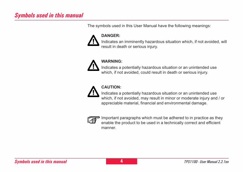
The symbols used in this User Manual have the following meanings:
DANGER:Indicates an imminently hazardous situation which, if not avoided, willresult in death or serious injury.
WARNING:Indicates a potentially hazardous situation or an unintended usewhich, if not avoided, could result in death or serious injury.
CAUTION:Indicates a potentially hazardous situation or an unintended usewhich, if not avoided, may result in minor or moderate injury and / orappreciable material, financial and environmental damage.
Important paragraphs which must be adhered to in practice as theyenable the product to be used in a technically correct and efficientmanner.
Symbols used in this manual
Symbols used in this manual
5TPS1100 - User Manual 2.2.1en
6
10
12
22
29
49
97
108
119
121
143
156
Contents
Introduction
Description of the system
Preparation, setting up
Checking and adjusting
System functions
System parameters
Data format
Care and transport
Safety directions
Technical specifications
Index
View of chapters
View of chapters
6 TPS1100 - User Manual 2.2.1enContents
ContentsIntroduction ................................................. 10
Validity ....................................................................... 11Documentation ........................................................... 11Instrument descriptions ............................................. 12
Description of the system........................... 12Distance measurement ............................................. 13Extended Range (Option) .......................................... 14Automatic Target Recognition ATR / LOCK ................ 15Quick Prism Search with PowerSearch ...................... 15Guide Light EGL ........................................................ 16RCS (Remote Controlled Surveying) .......................... 17System concept ......................................................... 18Leica Survey Office PC software package .................. 20Batteries and chargers............................................... 21
Preparation, setting up ............................... 22Unpacking ................................................................. 22Charging the battery .................................................. 23Inserting / replacing battery ........................................ 24Insert PC-card ........................................................... 26Setting up the instrument with optical plummet or laserplummet .................................................................... 27Levelling-up with the electronic bubble ....................... 28
Checking and adjusting .............................. 29Electronically ............................................................. 29
Compensator (electronic bubble) ................................... 32V-index error ................................................................... 34Line of sight .................................................................... 36Tilting axis ....................................................................... 38Combined error determination ........................................ 40Deactivating the instrument-error correction ................... 40ATR collimation ............................................................... 41
Mechanically ............................................................. 44Tripod ............................................................................. 44Bull's eye bubble on instrument ...................................... 44Bull's eye bubble on the tribrach ..................................... 44Optical plummet ............................................................. 45Laser plummet ................................................................ 46Reflector-free EDM ......................................................... 47
System functions ........................................ 49Data configuration ..................................................... 49
Data job (D JOB) and meas. job (M JOB) ....................... 49Creating a new job (NEW) .............................................. 50Codelist .......................................................................... 50Creating a new codelist (NEW) ....................................... 51Copying a codelist (COPY) ............................................. 51Data management .......................................................... 51Importing point data (IMPOR) ......................................... 53Displaying and importing point data (VIEW) ................... 54Displaying and editing GSI data (SEARC) ...................... 54
7TPS1100 - User Manual 2.2.1en
Contents (continued)
Contents
Placeholder (wild cards) in searching for points .............. 55Manual input of coordinates (INPUT) .............................. 56Converting data .............................................................. 56Formatting the PC-card (FORMT) ................................... 59Inspecting the PC-card (PROOF) ................................... 60Setting the recording mask (RMask) ............................... 60Setting the display mask (DMask) ................................... 61GSI-parameters .............................................................. 62
Measurement functions ............................................. 66Setting and entering the Hz direction (SetHz) ................. 67Distance measurement ................................................... 67Selecting the EDM measuring program,target type and reflector .................................................. 68Switch between IR/RL .................................................... 69Switch between Standard/Tracking ................................. 70Switch between Fast measurement/Rapid ...................... 70Tracking .......................................................................... 70Setting / defining prisms ................................................. 70EDM test ......................................................................... 71Distance corrections, ppm .............................................. 71Reduced distance corrections ppm................................. 73Measurement & recording (REC) .................................... 73Measuring distances and angles separately(DIST + REC) ................................................................. 74Measuring distances and angles togetherwith storage (ALL) .......................................................... 75Storing station data (REC) .............................................. 75Changing face (I<>II) ...................................................... 75
Last point number (L.Pt.) ................................................ 76Deleting the GSI block (Del B) ........................................ 76Manual distance entry ..................................................... 76Positioning the last point stored (LAST) .......................... 77V-angle modes ............................................................... 77Offset .............................................................................. 78Switching between display masks (>DISP) ..................... 78Individual point number (INDIV / RUN) ........................... 79Coding ............................................................................ 79Quick Coding (QCod+ / QCod-) ..................................... 81Check Orientation ........................................................... 82GSI communication parameters ..................................... 83
Communication ......................................................... 83Interface parameters (GeoCOM) .................................... 83RCS communication parameters .................................... 84On-line mode .................................................................. 84
Automatic Target Recognition .................................... 85Functionality ................................................................... 85ATR-Mode (ATR+ / ATR-) ............................................... 86LOCK-Mode (LOCK+ / LOCK-) ....................................... 86L.UNT-Mode (L.INT+ / L.GO) .......................................... 87LAST mode (LAST) ........................................................ 88Hz / V ............................................................................. 88
Automatic Reflector Search ....................................... 89RCS Searching Window ................................................. 90Definition of a Working Area (WORKA) .......................... 91Activate/Deactivate Working Area (WORK+/WORK-) ..... 92
8 TPS1100 - User Manual 2.2.1enContents
Contents (continued)General functions ...................................................... 92
Instrument designation and software version (INFO) ...... 92Electronic bubble (LEVEL) .............................................. 92Illumination ..................................................................... 93Accessories .................................................................... 94Loading a configuration file (LOAD) ................................ 95Loading a system-parameter file ..................................... 96
System parameters ..................................... 97General parameters .................................................. 97
Load application ............................................................. 97Load system language ................................................... 97Date ................................................................................ 98Date form. ....................................................................... 98Time ............................................................................... 98Alpha mode .................................................................... 98Time form. ...................................................................... 98Key beep ........................................................................ 98
Configuration parameters .......................................... 99Autoexec. ....................................................................... 99Language ....................................................................... 99Dist. Unit ......................................................................... 99Dist. Dec. ........................................................................ 99Angle Unit ....................................................................... 99Angle Dec. ...................................................................... 99Temp. Unit .................................................................... 100Press. Unit .................................................................... 100
Coord. Seq. .................................................................. 100Hz system..................................................................... 100Face I ........................................................................... 100Compensator ................................................................ 101Hz-Corr. ........................................................................ 101Sect. Beep .................................................................... 102Sect. Angle ................................................................... 102Release V-angle ........................................................... 102V-Display ...................................................................... 103Power mode ................................................................. 103Power Time .................................................................. 103Dist. Delay .................................................................... 103PPM entry ..................................................................... 104Info / Atrib ..................................................................... 104Auto Dist ....................................................................... 105
Measurement parameters ....................................... 105Pt. Id. mode .................................................................. 105Offs. Mode .................................................................... 105Increment ..................................................................... 106
Work settings .......................................................... 107Meas Job ...................................................................... 107Data Job ....................................................................... 107Codelist ........................................................................ 107Quick-Code .................................................................. 107
Data format ................................................ 108Introduction ............................................................. 108
9TPS1100 - User Manual 2.2.1en
Contents (continued)
Contents
Format with 8 or 16 characters ................................ 108Block concept .......................................................... 109Structure of a block ................................................. 109Measurement block .................................................. 110Code block ............................................................... 110Terminator of a data block ........................................ 110Structure of a word ................................................... 111
Word index (positions 1 - 2) ........................................... 111Information relating to data (positions 3 - 6) .................. 112Data (positions 7 - 15/23) ............................................. 113Separating character (position 16/24) ........................... 114Block number ............................................................... 114Units of measurement .................................................. 115
Example of data format ............................................ 115Format of a theodolite measurement block ................... 116Format of a code block ................................................. 118
Care and transport .....................................119Transport ................................................................. 119Maintainance for motorized drives ............................. 119Storage ................................................................... 120Cleaning and drying ................................................. 120
Safety directions ....................................... 121Intended use of instrument ...................................... 121
Permitted uses ............................................................. 121Prohibited uses ............................................................. 121
Limits of use ............................................................ 122Responsibilities ....................................................... 123Hazards of use ........................................................ 123
Main hazards of use ..................................................... 123Laser classification .................................................. 127
Integrated distancer (infrared laser) ............................. 128Integrated distancer (visible laser) ............................... 129Automatic target recognition (ATR) ............................... 134PowerSearch ................................................................ 136Guide light EGL ............................................................ 137Laser plummet .............................................................. 138
Electromagnetic Compatibility (EMC) ....................... 140FCC statement (applicable in U.S.) .......................... 142
Technical specifications ........................... 143EGL Guide Light ...................................................... 148Automatic Target Recognition ATR .......................... 149PowerSearch .......................................................... 150Application programs ............................................... 150Scale correction (ppm) ............................................ 151
Atmospheric correction DD1 ......................................... 152Reduction to mean sea level DD2 ................................ 153Projection distortion DD3 .............................................. 153
Atmospheric corrections .......................................... 154Reduction formulae ................................................. 155
Index ........................................................... 156
10Introduction TPS1100 - User Manual 2.2.1en
6 All TPS1100 instruments areroutinely supplied with a laserplummet located in the vertical axis.The TPS1100 can therefore be setup quickly and accurately over theground point with the help of the redlaser dot.
The A-versions have an automatictarget recognition (ATR), whichpermits rapid, fatigue-freemeasuring. In ATR mode the fine-pointing is automatic. In LOCK modean already-targeted point is trackedautomatically.For TPS1100 plus instruments anoptional PowerSearch module isavailable which allows an automaticprism detection within a short periodof time.
The EGL guide light is an optionalaccessory for assistance withtargeting. It is located within thetelescope and it flashes, so that theperson carrying the reflector can
IntroductionTPS1100 stands for Total StationPositioning System. The TPS1100instruments are available as variousmodels with differing classes ofaccuracy. New technologies haveenabled the measuring sequence tobe largely automated, bringingadvantages such as shortermeasuring times, simpler operationand more efficient use. Furtherelements in the basic equipment aredescribed below.
The R versions have a laser with avisible red beam. The EDM can beswitched between two operationalmodes: measurements with normalinfrared or with the visible red laserrespectively. With the red laser,reflectors are not required formeasuring distances. With infrared,distances of up to seven kilometrescan be measured.
place this in the line of sight of theinstrument.The RCS1100 remote control systemis an additional option, which allowsthe remote control of all total stations.The instrument can be controlledeither directly on the instrument or atthe RCS1100. Especially theA-versions enable the surveyor towork alone.The measurements can also betriggered, inspected and controlledfrom the target area.
Leica Geosystems offersapplications programs for many dif-ferent tasks in surveying. Justchoose the software which bestmeets your needs.
Within the special GeoBasicprogramming environment, you cancreate your own application-specificprograms for the TPS1100instruments.

11TPS1100 - User Manual 2.2.1en Introduction
6Printed short instructions for thesystem and for the applications areavailable as well as the present usermanual. The enclosed CD ROMcontains the entire documentation inelectronic form.
� User manual:This includes all directions forusing the instrument and providesan overview of the system togetherwith important instructions andsafety directions.
� System Field Manual:This describes the functions of thesystem in standard use (ininstrument case).
� Application Programs FieldManual 1 + 2:This describes the functions of theprograms in standard use (ininstrument case).
� Application Programs ReferenceManual:All programs are described in de-tail.
The PC cards familiar in thecomputer industry are also used asthe medium for storing data in theTPS1100. The data structures arecompatible with those in existing Lei-ca Geosystems total stations.
Leica Survey Office is aPC-program package which supportsthe TPS1100 and RCS1100instruments and which enables datato be exchanged between softwareand hardware components.
This manual applies to all TPS1100Professional Series instruments.
Differences between the variousmodels are clearly set out andassigned.
General text applies to all types.
For purposes of pictorial illustration,we have selected a TCA model of theTPS1100 Professional Series withEGL options. The illustrations arevalid for all models.
Validity Documentation
12 TPS1100 - User Manual 2.2.1enDescription of the system
6
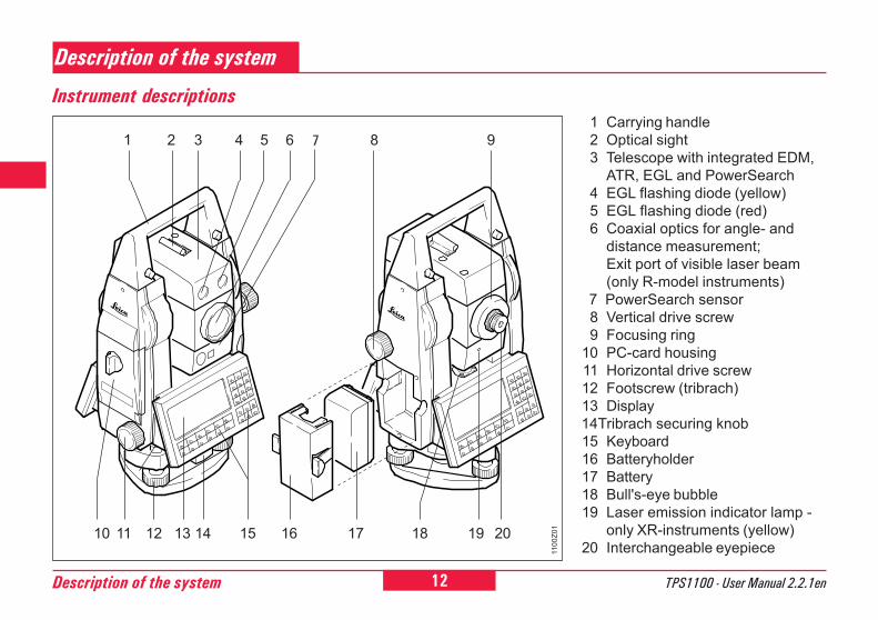
01 Carrying handle2 Optical sight3 Telescope with integrated EDM,
ATR, EGL and PowerSearch4 EGL flashing diode (yellow)5 EGL flashing diode (red)6 Coaxial optics for angle- and
distance measurement;Exit port of visible laser beam(only R-model instruments)
7 PowerSearch sensor8 Vertical drive screw9 Focusing ring
10 PC-card housing11 Horizontal drive screw12 Footscrew (tribrach)13 Display14Tribrach securing knob15 Keyboard16 Batteryholder17 Battery18 Bull's-eye bubble19 Laser emission indicator lamp -
only XR-instruments (yellow)20 Interchangeable eyepiece
Description of the system
Instrument descriptions
12 13 15
2
1110
1 3 4 5 6
16
9
1100
Z01
8
14 18 1917 20
7
13TPS1100 - User Manual 2.2.1en Description of the system
6
10
A laser distancer (EDM) is incorporatedinto the instruments of the newTPS1100 series.In all versions, the distance can bedetermined by using an invisibleinfrared beam which emerges coaxiallyfrom the telescope objective.
Very short distances may bemeasured reflectorless in
Infrared-mode (e.g. to well reflectingtargets like traffic signs). In this casethe distances are corrected with theaddition constant defined for theactive reflector.For applications without reflector, theTCR and TCRA version also use avisible red laser beam which emergesin the same manner. A specialarrangement of the EDM, andappropriate arrangement of the beampaths, enable ranges of over fivekilometres to be attained with standardprisms; miniprisms, 360° reflectors, andreflector tapes can also be used, andmeasurement is also possible without areflector.
Distance measurement
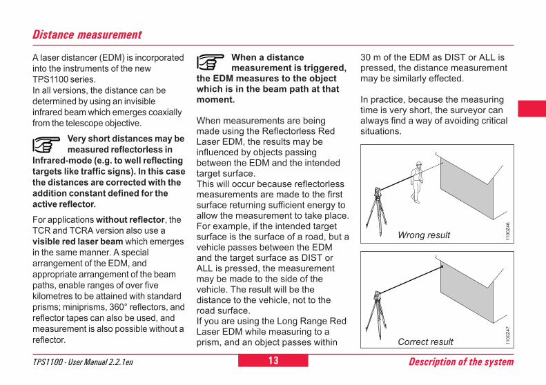
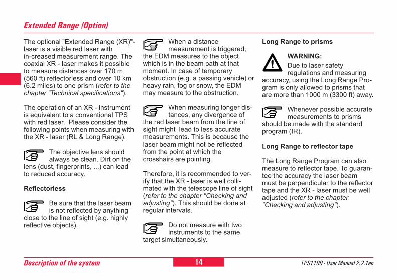
When a distancemeasurement is triggered,
the EDM measures to the objectwhich is in the beam path at thatmoment.
When measurements are beingmade using the Reflectorless RedLaser EDM, the results may beinfluenced by objects passingbetween the EDM and the intendedtarget surface.This will occur because reflectorlessmeasurements are made to the firstsurface returning sufficient energy toallow the measurement to take place.For example, if the intended targetsurface is the surface of a road, but avehicle passes between the EDMand the target surface as DIST orALL is pressed, the measurementmay be made to the side of thevehicle. The result will be thedistance to the vehicle, not to theroad surface.If you are using the Long Range RedLaser EDM while measuring to aprism, and an object passes within
30 m of the EDM as DIST or ALL ispressed, the distance measurementmay be similarly effected.
In practice, because the measuringtime is very short, the surveyor canalways find a way of avoiding criticalsituations.
Wrong result
Correct result
1100
Z46
1100
Z47
14 TPS1100 - User Manual 2.2.1enDescription of the system
6
0
The optional "Extended Range (XR)"-laser is a visible red laser within-creased measurement range. Thecoaxial XR - laser makes it possibleto measure distances over 170 m(560 ft) reflectorless and over 10 km(6.2 miles) to one prism (refer to thechapter "Technical specifications").
The operation of an XR - instrumentis equivalent to a conventional TPSwith red laser. Please consider thefollowing points when measuring withthe XR - laser (RL & Long Range).
The objective lens shouldalways be clean. Dirt on the
lens (dust, fingerprints, ...) can leadto reduced accuracy.
Reflectorless
Be sure that the laser beamis not reflected by anything
close to the line of sight (e.g. highlyreflective objects).
Extended Range (Option)
Long Range to prisms
WARNING:Due to laser safetyregulations and measuring
accuracy, using the Long Range Pro-gram is only allowed to prisms thatare more than 1000 m (3300 ft) away.
Whenever possible accuratemeasurements to prisms
should be made with the standardprogram (IR).
Long Range to reflector tape
The Long Range Program can alsomeasure to reflector tape. To guaran-tee the accuracy the laser beammust be perpendicular to the reflectortape and the XR - laser must be welladjusted (refer to the chapter"Checking and adjusting").
When a distancemeasurement is triggered,
the EDM measures to the objectwhich is in the beam path at thatmoment. In case of temporaryobstruction (e.g. a passing vehicle) orheavy rain, fog or snow, the EDMmay measure to the obstruction.
When measuring longer dis-tances, any divergence of
the red laser beam from the line ofsight might lead to less accuratemeasurements. This is because thelaser beam might not be reflectedfrom the point at which thecrosshairs are pointing.
Therefore, it is recommended to ver-ify that the XR - laser is well colli-mated with the telescope line of sight(refer to the chapter "Checking andadjusting"). This should be done atregular intervals.
Do not measure with twoinstruments to the same
target simultaneously.
15TPS1100 - User Manual 2.2.1en Description of the system
6
10
TCA and TCRA instruments aremotorized and equipped withAutomatic Target Recognition (ATR)coaxially in the telescope. The guidelight (EGL), mounted on thetelescope, isoptional.
ATR mode
These instruments permit automaticangle and distance measurements tonormal prisms and reduce the tediumof precise visual sighting to prisms.The prism is sighted with the opticalsight only. Initiating a distancemeasurement will turn the instrumentwith the help of the motors to sightthe prism-centre automatically.The angles V and Hz are measuredto the centre of the prism completionof the distance measurement.
Automatic Target Recognition ATR / LOCK
LOCK mode
Lock mode will enable TCAinstruments to follow a moving prism.Distances can be measuredwhenever the prism stops for a shorttime ("Stop and Go mode").
If the assistant changes thelocation too quickly, the
target may be lost. Make sure thatthe speed does not exceed the figuregiven in the technical data.
As with all other instrumenterrors, the collimation error
of the automatic target recognition(ATR) must be redeterminedperiodically (Refer to chapter"Checking and Adjusting").
1100
Z55
Quick Prism Search withPowerSearch
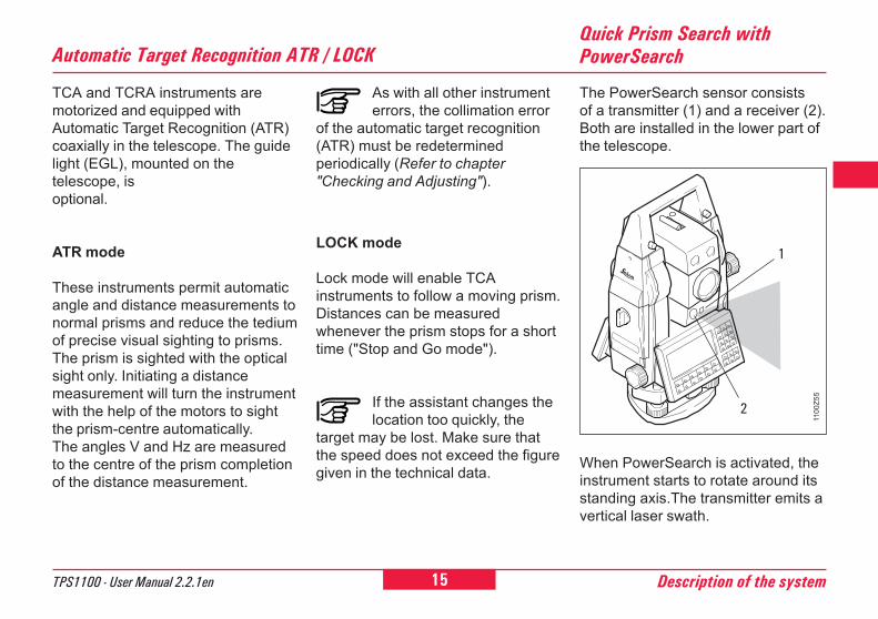
The PowerSearch sensor consistsof a transmitter (1) and a receiver (2).Both are installed in the lower part ofthe telescope.
When PowerSearch is activated, theinstrument starts to rotate around itsstanding axis.The transmitter emits avertical laser swath.
1
2
16 TPS1100 - User Manual 2.2.1enDescription of the system
6
0
Guide Light EGL
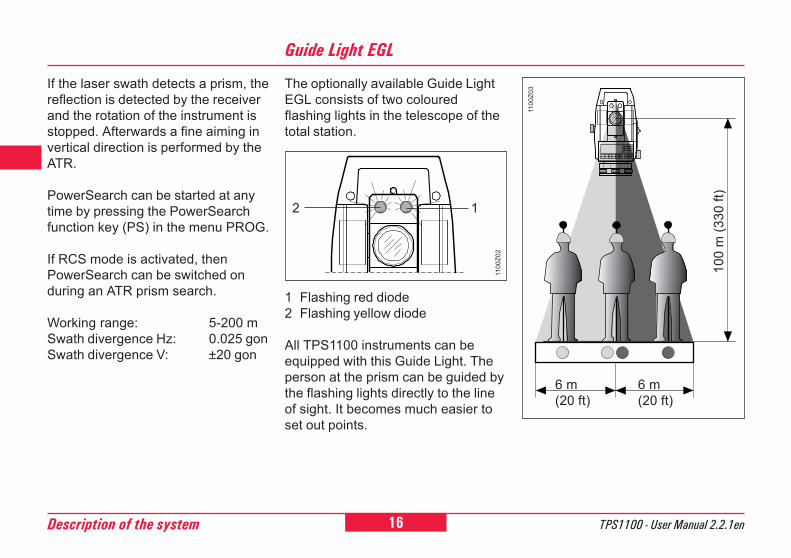
The optionally available Guide LightEGL consists of two colouredflashing lights in the telescope of thetotal station.
1 Flashing red diode2 Flashing yellow diode
All TPS1100 instruments can beequipped with this Guide Light. Theperson at the prism can be guided bythe flashing lights directly to the lineof sight. It becomes much easier toset out points.
12
1100
Z02
1100
Z03
6 m(20 ft)
6 m(20 ft)
100
m (3
30 ft
)
If the laser swath detects a prism, thereflection is detected by the receiverand the rotation of the instrument isstopped. Afterwards a fine aiming invertical direction is performed by theATR.
PowerSearch can be started at anytime by pressing the PowerSearchfunction key (PS) in the menu PROG.
If RCS mode is activated, thenPowerSearch can be switched onduring an ATR prism search.
Working range: 5-200 mSwath divergence Hz: 0.025 gonSwath divergence V: ±20 gon
17TPS1100 - User Manual 2.2.1en Description of the system
6
10
At a target distance of 100 metres(330 ft) a red/yellow flashing cone oflight with a width of 6m (20 ft) isformed on each side. As a result,guiding to the line of sight of theinstrument is much easier and faster.
Between the two cones of light asector about 30mm wide is created.Within this sector both colours areflashing simultaneously. In this casethe prism is already right in the line ofsight.
Operating range:5 - 150 m (15 -500 ft)
Divergence:10 m (33ft) at 100m (330 ft)
RCS (Remote Controlled Surveying)
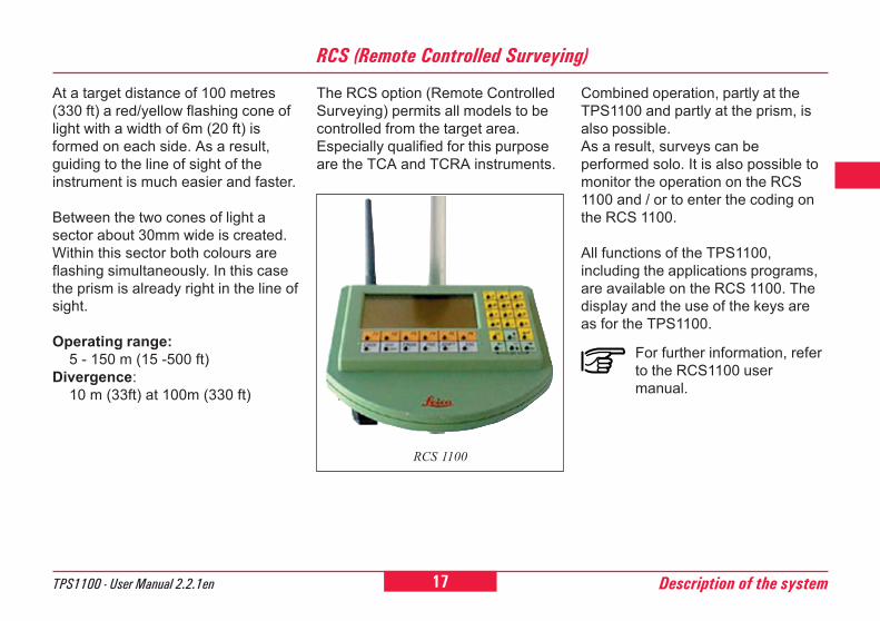
The RCS option (Remote ControlledSurveying) permits all models to becontrolled from the target area.Especially qualified for this purposeare the TCA and TCRA instruments.
RCS 1100
For further information, referto the RCS1100 usermanual.
Combined operation, partly at theTPS1100 and partly at the prism, isalso possible.As a result, surveys can beperformed solo. It is also possible tomonitor the operation on the RCS1100 and / or to enter the coding onthe RCS 1100.
All functions of the TPS1100,including the applications programs,are available on the RCS 1100. Thedisplay and the use of the keys areas for the TPS1100.
18 TPS1100 - User Manual 2.2.1enDescription of the system
6
0
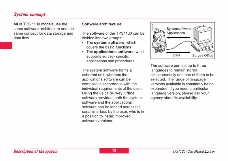
Software architecture
The software of the TPS1100 can bedivided into two groups:� The system software, which
covers the basic functions� The applications software, which
supports survey- specificapplications and procedures.
The system software forms acoherent unit, whereas theapplications software can becompiled in accordance with theindividual requirements of the user.Using the Leica Survey Officesoftware provided, both the systemsoftware and the applicationssoftware can be loaded across theserial interface by the user, who is ina position to install improvedsoftware versions.
System concept
All of TPS 1100 models use thesame software architecture and thesame concept for data storage anddata flow.
The software permits up to threelanguages to remain storedsimultaneously and one of them to beselected. The range of languageversions available is constantly beingexpanded. If you need a particularlanguage version, please ask youragency about its availability.
Survey Office
Systemsoftware,Applications
1100
Z04
Data
19TPS1100 - User Manual 2.2.1en Description of the system
6
10
System concept, continued
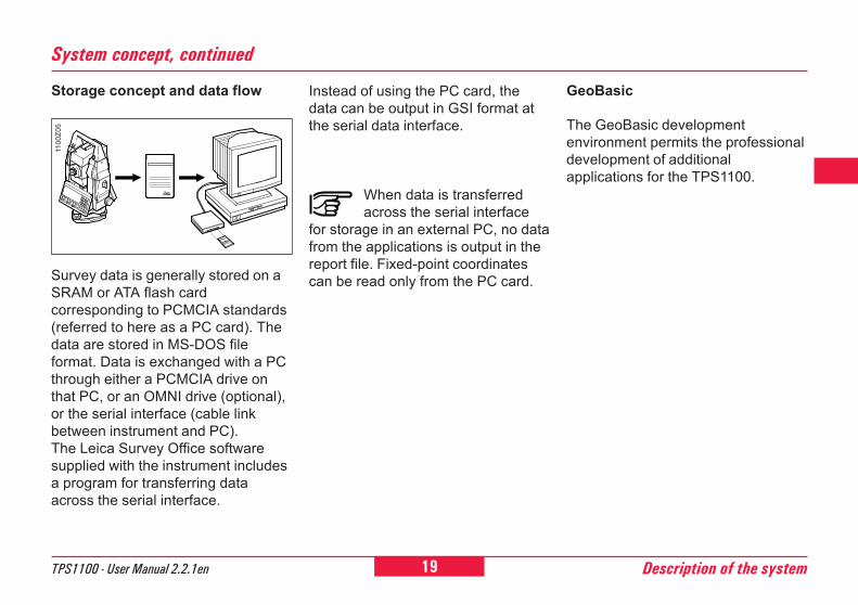
Survey data is generally stored on aSRAM or ATA flash cardcorresponding to PCMCIA standards(referred to here as a PC card). Thedata are stored in MS-DOS fileformat. Data is exchanged with a PCthrough either a PCMCIA drive onthat PC, or an OMNI drive (optional),or the serial interface (cable linkbetween instrument and PC).The Leica Survey Office softwaresupplied with the instrument includesa program for transferring dataacross the serial interface.
Instead of using the PC card, thedata can be output in GSI format atthe serial data interface.
When data is transferredacross the serial interface
for storage in an external PC, no datafrom the applications is output in thereport file. Fixed-point coordinatescan be read only from the PC card.
GeoBasic
The GeoBasic developmentenvironment permits the professionaldevelopment of additionalapplications for the TPS1100.
Storage concept and data flow
1100
Z05
20 TPS1100 - User Manual 2.2.1enDescription of the system
6
0
Range of programs
After the installation is complete, thefollowing programs are available:� Data Exchange Manager:
Exchange of data between theinstrument and the PC.
� Codelists Manager:Creates code lists.
� Software Upload:Loading and deleting systemssoftware, applications programs,systems texts and applicationstexts.
� Coordinate Editor:Editing of coordinates.
Optionally, additional programs canbe installed.
Leica Survey Office PC software package
The Leica Survey Office softwareincludes a series of help programswhich support you in your work withthe TPS1100 total station.
Installing in the PCThe installation program for LeicaSurvey Office is located on theTPS1100 CD-ROM supplied with thepresent handbook. Please note thatSurvey Office can only be installed onthe following operating systems:MS Windows 95/98/Me andMS Windows NT4.0/2000/XP.
To install the program, first call up theprogram "setup.exe" from thedirectory \SurveyOffice\English\Disk1\ on the CD-ROM, andcarry out the instructions given. Forfurther information, refer to thehandbook or to the on-line helpprovided by your operating system.
For additional informationabout Leica Survey Office,please refer to thecomprehensive on-line help.

21TPS1100 - User Manual 2.2.1en Description of the system
6
10
Your Leica Geosystems instrument ispowered by rechargeable batterymodules. The Pro battery (GEB121)is recommended for the TPS1100Professional Series. The basicbattery (GEB111) is an optional alter-native.
Use only the Leica Geosy-stems batteries, chargers andaccessories, or accessoriesrecommended by Leica Geo-systems.
The adapter plate GDI121 can beconnected to the Pro charger(GKL122) or to the GKL23 charger,and enables two Pro / Basic batteriesto be charged simultaneously.
Batteries and chargers
The Professional charger (GKL122)will charge up to four batteries, eitherfrom a 230V or 115V power sourceusing a power plug or from the 12Vor 24V source provided by thecigarette lighter in a vehicle. At anyone time, either two Pro / Basicbatteries can be charged or, by usingthe adapter plate (GDI121), four Pro /Basic batteries.
1100
Z07
1100
Z08
Power cable
ChargerGKL122
Vehicle battery cable
Charging cableAdapter plateGDI121
ChargerGKL23
Adapter plateGDI12111
00Z0
6
GEB111
GEB121
22 TPS1100 - User Manual 2.2.1enPreparing to measure, setting up
6
0
2
Preparation, setting up
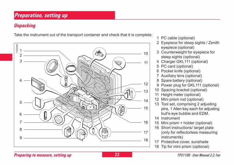
Take the instrument out of the transport container and check that it is complete:
Unpacking
1 PC cable (optional)2 Eyepiece for steep sights / Zenith
eyepiece (optional)3 Counterweight for eyepiece for
steep sights (optional)4 Charger GKL111 (optional)5 PC card (optional)6 Pocket knife (optional)7 Auxiliary lens (optional)8 Spare battery (optional)9 Power plug for GKL111 (optional)
10 Spacing bracket (optional)11 Height meter (optional)12 Mini prism rod (optional)13 Tool set, comprising 2 adjusting
pins, 1 Allen key each for adjustingbull's-eye bubble and EDM.
14 Instrument15 Mini prism + holder (optional)16 Short instructions/ target plate
(only for reflectorless measuringinstruments)
17 Protective cover, sunshade18 Tip for mini prism (optional)
1100
Z09B
3
4
14
15
17
5
7
6
16
18
12
1
8
2
9
13
11
10
23TPS1100 - User Manual 2.2.1en Preparing to measure, setting up
6
10
12
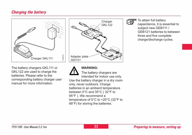
Charging the battery
WARNING:The battery chargers areintended for indoor use only.
Use the battery charger in a dry roomonly, never outdoors. Chargebatteries in an ambient temperaturebetween 0°C and 35°C ( 32°F to95°F ). We recommend atemperature of 0°C to +20°C (32°F to68°F) for storing the batteries.
1100
Z10
The battery chargers GKL111 orGKL122 are used to charge thebatteries. Please refer to thecorresponding battery charger usermanual for more information.
1100
Z07
ChargerGKL122
Adapter plateGDI121Charger GKL111
To attain full batterycapacitance, it is essential tosubject new GEB111 /GEB121 batteries to betweenthree and five completecharge/discharge cycles.
24 TPS1100 - User Manual 2.2.1enPreparing to measure, setting up
6
0
2
1100
Z12
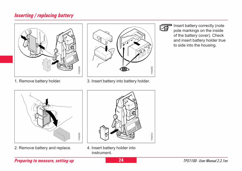
Insert battery correctly (notepole markings on the insideof the battery cover). Checkand insert battery holder trueto side into the housing.
2. Remove battery and replace. 4. Insert battery holder intoinstrument.
3. Insert battery into battery holder.
Inserting / replacing battery
1. Remove battery holder.11
00Z4
811
00Z4
9
1100
Z50
25TPS1100 - User Manual 2.2.1en Preparing to measure, setting up
6
10
12
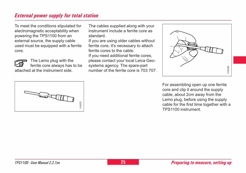
External power supply for total station
To meet the conditions stipulated forelectromagnetic acceptability whenpowering the TPS1100 from anexternal source, the supply cableused must be equipped with a ferritecore.
The Lemo plug with theferrite core always has to be
attached at the instrument side.
The cables supplied along with yourinstrument include a ferrite core asstandard.If you are using older cables withoutferrite core, it's necessary to attachferrite cores to the cable.If you need additional ferrite cores,please contact your local Leica Geo-systems agency. The spare-partnumber of the ferrite core is 703 707.
For assembling open up one ferritecore and clip it around the supplycable, about 2cm away from theLemo plug, before using the supplycable for the first time together with aTPS1100 instrument.11
00Z5
7
1100
Z58
26 TPS1100 - User Manual 2.2.1enPreparing to measure, setting up
6
0
2
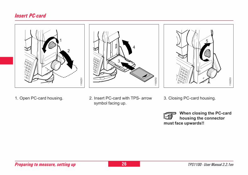
Insert PC-card
2. Insert PC-card with TPS- arrowsymbol facing up.
1. Open PC-card housing.
1100
Z52
1100
Z53
1100
Z51
3. Closing PC-card housing.
When closing the PC-cardhousing the connector
must face upwards!!
1
2
3
45
27TPS1100 - User Manual 2.2.1en Preparing to measure, setting up
6
10
12
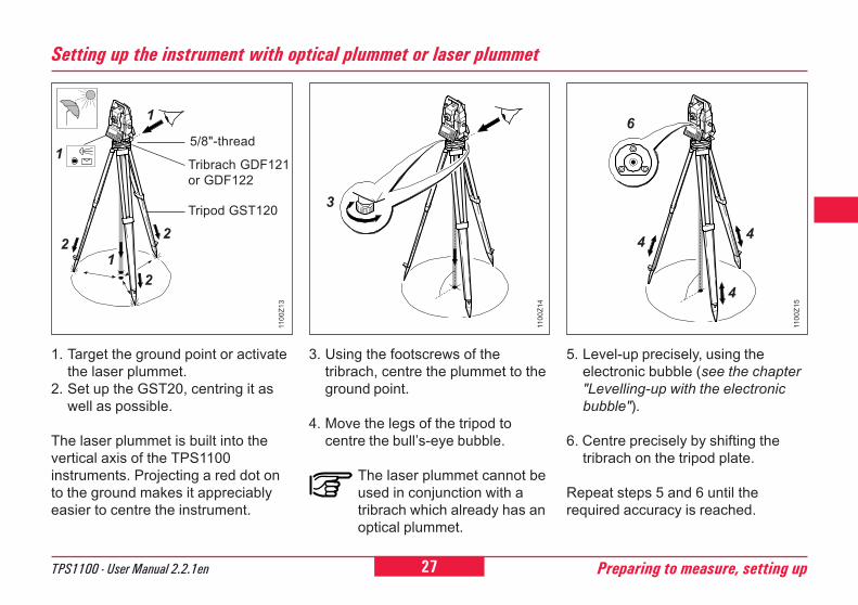
3. Using the footscrews of thetribrach, centre the plummet to theground point.
4. Move the legs of the tripod tocentre the bull�s-eye bubble.
The laser plummet cannot beused in conjunction with atribrach which already has anoptical plummet.
5. Level-up precisely, using theelectronic bubble (see the chapter"Levelling-up with the electronicbubble").
6. Centre precisely by shifting thetribrach on the tripod plate.
Repeat steps 5 and 6 until therequired accuracy is reached.
1. Target the ground point or activatethe laser plummet.
2. Set up the GST20, centring it aswell as possible.
The laser plummet is built into thevertical axis of the TPS1100instruments. Projecting a red dot onto the ground makes it appreciablyeasier to centre the instrument.
Setting up the instrument with optical plummet or laser plummet
5/8"-thread
2
Tripod GST120
Tribrach GDF121or GDF122
1
12
2
1100
Z13
3
1100
Z14
4
4
6
4
1100
Z15
1
28 TPS1100 - User Manual 2.2.1enPreparing to measure, setting up
6
0
2
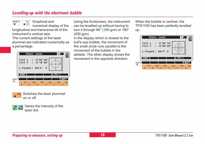
Switches the laser plummeton or off.
Varies the intensity of thelaser dot.
Graphical andnumerical display of the
longitudinal and transverse tilt of theinstrument�s vertical axis.The current settings of the laserplummet are indicated numerically asa percentage.
Levelling-up with the electronic bubble
Using the footscrews, the instrumentcan be levelled-up without having toturn it through 90° (100 gon) or 180°(200 gon).In the display which is closest to thebull's-eye bubble, the movement ofthe small circle runs parallel to themovement of the bubble in thealidade. The other display shows themovement in the opposite direction.
When the bubble is centred, theTPS1100 has been perfectly levelledup.
Elect. Level
Tilt L : -0°03'40"Tilt T : -0°18'30"
L.Plumet : 50% X
CONT L.Pl+
MC
QUIT
Elect. Level
Tilt L : -0°00'10"Tilt T : -0°00'20"
L.Plumet : 50% X
CONT L.Pl+
MC
QUIT
29TPS1100 - User Manual 2.2.1en Checking and adjusting
6
10
12
21
Checking and adjusting
All instruments basically haveinherent mechanical defects whichcan affect the measurement ofangles. The electronic angle-measuring system of the TPS1100routinely corrects the mechanicalinstrument errors listed below; thevertical angles relate to the plumbline and the horizontal measurementsare corrected for line-of-sight error,for tilting-axis error and for vertical-axis tilt:
� l, t Compensator index error� i Vertical-index error� c Line-of-sight error� a Tilting-axis error� ATR ATR zero-point error (only for
TCA and TCRA versions)
Take note that the procedurefor determining the relevant
instrument error has to be followedprecisely and carefully.
The determination of theinstrument errors can be
started in any telescope face.
Immediately after the firstmeasurement has been
completed, motorized instrumentschange automatically to the secondface, after which the user merelyneeds to carry out the fine pointing.
Electronically
The instrument errors listed on theleft can change over time and withtemperature.
They should, therefore, beredetermined in the order shownbelow:� before the first use� before each precision survey� after long periods of transport� after long periods of work� if the temperature alters by more
than 20°C
Before determining the instrumenterrors, level-up the instrument usingthe electronic bubble. The instrumentshould be secure and firm, andshould be protected from directsunlight in order to avoid thermalwarming on one side only.
30 TPS1100 - User Manual 2.2.1enChecking and adjusting
6
0
2
21
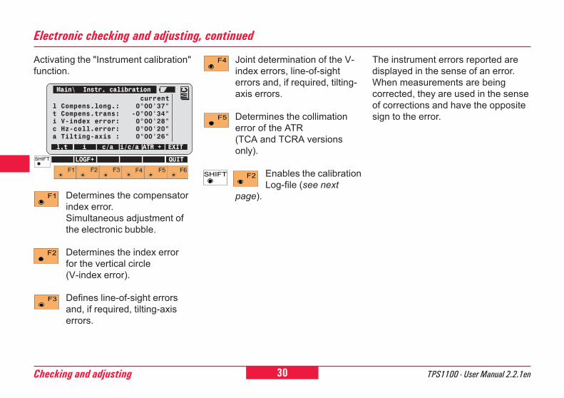
Determines the compensatorindex error.Simultaneous adjustment ofthe electronic bubble.
Determines the index errorfor the vertical circle(V-index error).
Defines line-of-sight errorsand, if required, tilting-axiserrors.
Joint determination of the V-index errors, line-of-sighterrors and, if required, tilting-axis errors.
Determines the collimationerror of the ATR(TCA and TCRA versionsonly).
Enables the calibrationLog-file (see next
page).
Activating the "Instrument calibration"function.
Electronic checking and adjusting, continued
The instrument errors reported aredisplayed in the sense of an error.When measurements are beingcorrected, they are used in the senseof corrections and have the oppositesign to the error.
Main\ Instr. calibrationcurrent
l Compens.long.: 0°00'37"t Compens.trans: -0°00'34"i V-index error: 0°00'28"c Hz-coll.error: 0°00'20"a Tilting-axis : 0°00'26"
l,t i c/a i/c/a ATR + EXIT
MC
LOGF+ QUIT
31TPS1100 - User Manual 2.2.1en Checking and adjusting
6
10
12
21
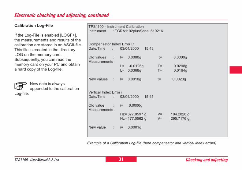
Calibration Log-File
If the Log-File is enabled [LOGF+],the measurements and results of thecalibration are stored in an ASCII-file.This file is created in the directoryLOG on the memory card.Subsequently, you can read thememory card on your PC and obtaina hard copy of the Log-file.
New data is alwaysappended to the calibration
Log-file.
TPS1100 - Instrument CalibrationInstrument : TCRA1102plusSerial 619216
Compensator Index Error l,tDate/Time : 03/04/2000 15:43
Old values : l= 0.0000g t= 0.0000gMeasurements
L= -0.0126g T= 0.0298gL= 0.0368g T= 0.0164g
New values : l= 0.0010g t= 0.0023g
Vertical Index Error iDate/Time : 03/04/2000 15:45
Old value : i= 0.0000gMeasurements
Hz= 377.0597 g V= 104.2828 gHz= 177.0562 g V= 295.7176 g
New value : i= 0.0001g
Example of a Calibration Log-file (here compensator and vertical index errors)
Electronic checking and adjusting, continued
32 TPS1100 - User Manual 2.2.1enChecking and adjusting
6
0
2
21
Initiate the measurement ofthe longitudinal and
transverse tilt ( l, t ).
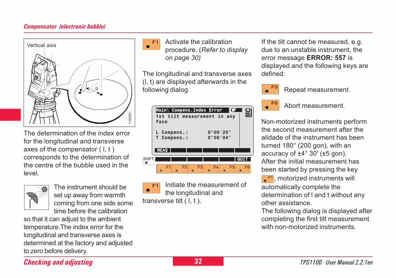
Compensator (electronic bubble)
The determination of the index errorfor the longitudinal and transverseaxes of the compensator ( l, t )corresponds to the determination ofthe centre of the bubble used in thelevel.
The instrument should beset up away from warmthcoming from one side sometime before the calibration
so that it can adjust to the ambienttemperature.The index error for thelongitudinal and transverse axes isdetermined at the factory and adjustedto zero before delivery.
Activate the calibrationprocedure. (Refer to displayon page 30)
The longitudinal and transverse axes(l, t) are displayed afterwards in thefollowing dialog.
Vertical axis If the tilt cannot be measured, e.g.due to an unstable instrument, theerror message ERROR: 557 isdisplayed and the following keys aredefined:
Repeat measurement.
Abort measurement.
Non-motorized instruments performthe second measurement after thealidade of the instrument has beenturned 180° (200 gon), with anaccuracy of ±4° 30' (±5 gon).After the initial measurement hasbeen started by pressing the key
, motorized instruments willautomatically complete thedetermination of l and t without anyother assistance.The following dialog is displayed aftercompleting the first tilt measurementwith non-motorized instruments.
Main\ Compens.Index Error1st tilt measurement in anyface
L Compens.: 0°00'25"T Compens.: 0°00'04"
MEAS
MC
QUIT
ql
1100
Z01
33TPS1100 - User Manual 2.2.1en Checking and adjusting
6
10
12
21
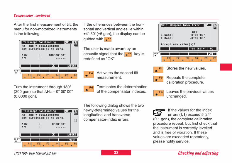
After the first measurement of tilt, themenu for non-motorized instrumentsis the following:
Turn the instrument through 180°(200 gon) so that ∆Hz = 0° 00' 00"(0.0000 gon).
Compensator , continued
If the differences between the hori-zontal and vertical angles lie within±4° 30' (±5 gon), the display can bequitted with .
The user is made aware by anacoustic signal that the -key isredefined as "OK".
Activates the second tiltmeasurement.
Terminates the determinationof the compensator indexes.
The following dialog shows the twonewly-determined values for thelongitudinal and transversecompensator-index errors.
Stores the new values.
Repeats the completecalibration procedure.
Leaves the previous valuesunchanged.
If the values for the indexerrors (l, t) exceed 5' 24"
(0.1 gon), the complete calibrationprocedure repeat, but first check thatthe instrument is correctly levelledand is free of vibration. If thesevalues are exceeded repeatedly,please notify service.
Telescope PositioningHz- and V-positioning:set direction(s) to zero.
∆ ∆ ∆ ∆ ∆ Hz : 0°00'00"∆ ∆ ∆ ∆ ∆ V : ------
OK ABORT
MC
QUIT
II
Telescope PositioningHz- and V-positioning:set direction(s) to zero.
∆ ∆ ∆ ∆ ∆ Hz : 180°00'00"∆ ∆ ∆ ∆ ∆ V : ------
OK ABORT
MC
Main\ Compens.Index Error
newl Comp: 0°03'02"t Comp: -0°02'06"
Accept new value(s)?
YES RETRY NO
MC
QUIT
34 TPS1100 - User Manual 2.2.1enChecking and adjusting
6
0
2
21
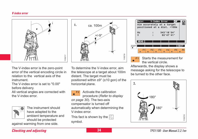
V-index error
The V-index error is the zero-pointerror of the vertical encoding circle inrelation to the vertical axis of theinstrument.The V-index error is set to "0.00"before delivery.All vertical angles are corrected withthe V-index error.
The instrument shouldhave adapted to theambient temperature andshould be protected
against warming from one side.
To determine the V-index error, aimthe telescope at a target about 100mdistant. The target must bepositioned within ±9° (±10 gon) of thehorizontal plane.
Activate the calibrationprocedure (Refer to display
on page 30). The two-axiscompensator is turned offautomatically when determining theV-index error.This fact is shown by the symbol.
Starts the measurement forthe vertical circle.
Afterwards, the display shows amessage asking for the telescope tobe turned to the other face.
i
1100
Z17
ca. 100m
+/-9°
1.
1100
Z18
2.
180°
180°
1100
Z19
Main\ V-Index ErrorAim accurately at a targetpositioned at a dist. >100m
Hz : 343°18'54"V : 93°47'41"
MEAS
MC
QUIT
35TPS1100 - User Manual 2.2.1en Checking and adjusting
6
10
12
21
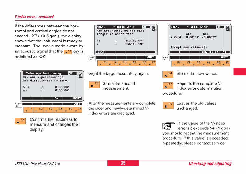
If the differences between the hori-zontal and vertical angles do notexceed ±27' ( ±0.5 gon ), the displayshows that the instrument is ready tomeasure. The user is made aware byan acoustic signal that the key isredefined as 'OK'.
V-index error , continued
Confirms the readiness tomeasure and changes thedisplay.
Sight the target accurately again.
Starts the secondmeasurement.
After the measurements are complete,the older and newly-determined V-index errors are displayed.
Stores the new values.
Repeats the complete V-index error determination
procedure.
Leaves the old valuesunchanged.
If the value of the V-indexerror (i) exceeds 54' (1 gon)
you should repeat the measurementprocedure. If this value is exceededrepeatedly, please contact service.
Main\ V-Index Error
old newi Vind: 0°00'03" -0°00'22"
Accept new value(s)?
YES RETRY NO
MC
QUIT
Telescope PositioningHz- and V-positioning:Set direction(s) to zero.
∆ ∆ ∆ ∆ ∆ Hz : 0°00'00"∆ ∆ ∆ ∆ ∆ V : 0°00'00"
OK ABORT
MC
QUIT
Main\ V-Index ErrorAim accurately at the sametarget in other face
Hz : 163°18'54"V : 266°12'19"
MEAS
MC
QUIT
36 TPS1100 - User Manual 2.2.1enChecking and adjusting
6
0
2
21
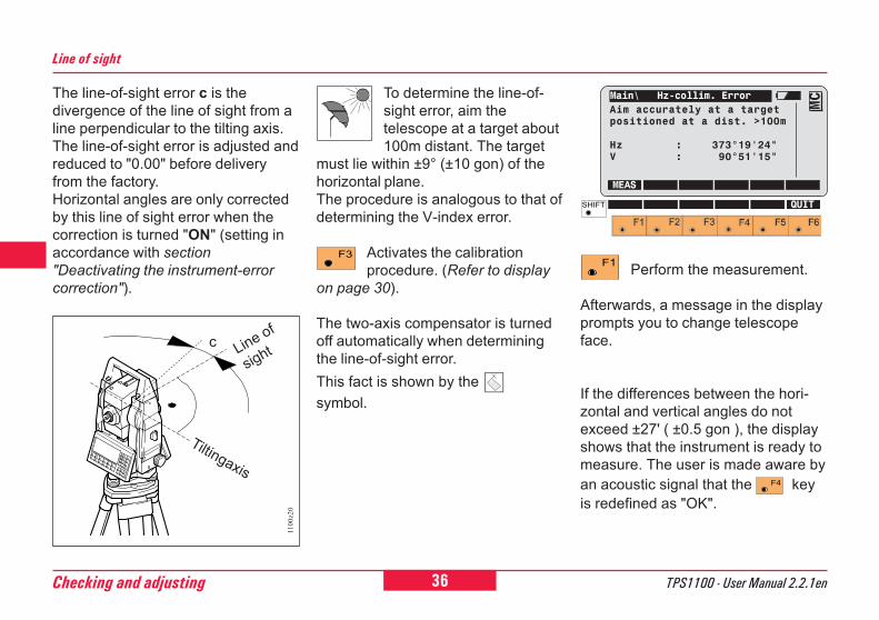
Line of sight
The line-of-sight error c is thedivergence of the line of sight from aline perpendicular to the tilting axis.The line-of-sight error is adjusted andreduced to "0.00" before deliveryfrom the factory.Horizontal angles are only correctedby this line of sight error when thecorrection is turned "ON" (setting inaccordance with section"Deactivating the instrument-errorcorrection").
To determine the line-of-sight error, aim thetelescope at a target about100m distant. The target
must lie within ±9° (±10 gon) of thehorizontal plane.The procedure is analogous to that ofdetermining the V-index error.
Activates the calibrationprocedure. (Refer to display
on page 30).
The two-axis compensator is turnedoff automatically when determiningthe line-of-sight error.This fact is shown by the symbol.
Perform the measurement.
Afterwards, a message in the displayprompts you to change telescopeface.
If the differences between the hori-zontal and vertical angles do notexceed ±27' ( ±0.5 gon ), the displayshows that the instrument is ready tomeasure. The user is made aware byan acoustic signal that the keyis redefined as "OK".
1100z20
c Line of
sight
Tiltingaxis
Main\ Hz-collim. ErrorAim accurately at a targetpositioned at a dist. >100m
Hz : 373°19'24"V : 90°51'15"
MEAS
MC
QUIT
37TPS1100 - User Manual 2.2.1en Checking and adjusting
6
10
12
21
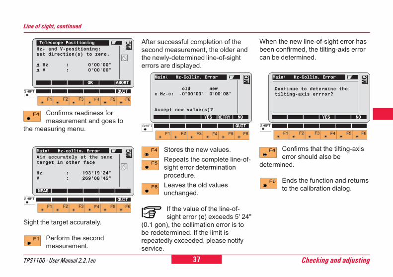
Line of sight, continued
Confirms readiness formeasurement and goes to
the measuring menu.
Sight the target accurately.
Perform the secondmeasurement.
Stores the new values.Repeats the complete line-of-sight error determinationprocedure.Leaves the old valuesunchanged.
If the value of the line-of-sight error (c) exceeds 5' 24"
(0.1 gon), the collimation error is tobe redetermined. If the limit isrepeatedly exceeded, please notifyservice.
When the new line-of-sight error hasbeen confirmed, the tilting-axis errorcan be determined.
Confirms that the tilting-axiserror should also be
determined.
Ends the function and returnsto the calibration dialog.
After successful completion of thesecond measurement, the older andthe newly-determined line-of-sighterrors are displayed.
Main\ Hz-Collim. Error
old newc Hz-c: -0°00'03" 0°00'08"
Accept new value(s)?
YES RETRY NO
MC
QUIT
Main\ Hz-Collim. Error
YES NO
MC
Continue to determine thetilting-axis errror?
Telescope PositioningHz- and V-positioning:set direction(s) to zero.
∆∆∆∆∆ Hz : 0°00'00"∆∆∆∆∆ V : 0°00'00"
OK ABORT
MC
QUIT
Main\ Hz-collim. ErrorAim accurately at the sametarget in other face
Hz : 193°19'24"V : 269°08'45"
MEAS
MC
QUIT
38 TPS1100 - User Manual 2.2.1enChecking and adjusting
6
0
2
21
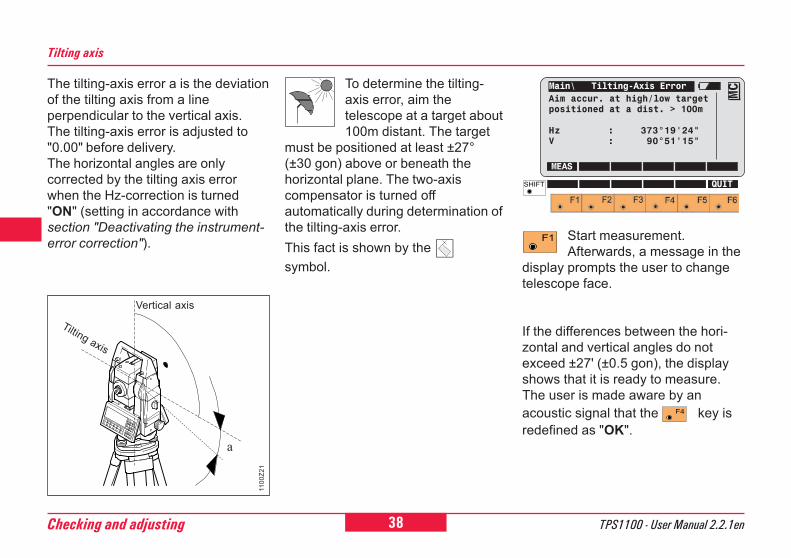
Tilting axis
The tilting-axis error a is the deviationof the tilting axis from a lineperpendicular to the vertical axis.The tilting-axis error is adjusted to"0.00" before delivery.The horizontal angles are onlycorrected by the tilting axis errorwhen the Hz-correction is turned"ON" (setting in accordance withsection "Deactivating the instrument-error correction").
Tilting axis
Vertical axis
To determine the tilting-axis error, aim thetelescope at a target about100m distant. The target
must be positioned at least ±27°(±30 gon) above or beneath thehorizontal plane. The two-axiscompensator is turned offautomatically during determination ofthe tilting-axis error.This fact is shown by the symbol.
Start measurement.Afterwards, a message in the
display prompts the user to changetelescope face.
If the differences between the hori-zontal and vertical angles do notexceed ±27' (±0.5 gon), the displayshows that it is ready to measure.The user is made aware by anacoustic signal that the key isredefined as "OK".
a
1100
Z21
Main\ Tilting-Axis ErrorAim accur. at high/low targetpositioned at a dist. > 100m
Hz : 373°19'24"V : 90°51'15"
MEAS
MC
QUIT
39TPS1100 - User Manual 2.2.1en Checking and adjusting
6
10
12
21
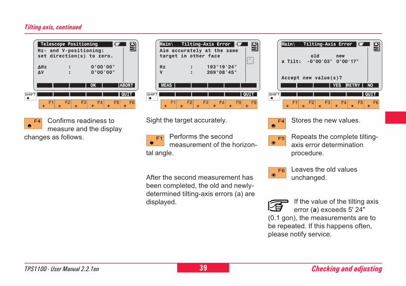
Confirms readiness tomeasure and the display
changes as follows.
Sight the target accurately.
Performs the secondmeasurement of the horizon-
tal angle.
After the second measurement hasbeen completed, the old and newly-determined tilting-axis errors (a) aredisplayed.
Stores the new values.
Repeats the complete tilting-axis error determinationprocedure.
Leaves the old valuesunchanged.
If the value of the tilting axiserror (a) exceeds 5' 24"
(0.1 gon), the measurements are tobe repeated. If this happens often,please notify service.
Tilting axis, continued
Main\ Tilting-Axis Error
old newa Tilt: -0°00'03" 0°00'17"
Accept new value(s)?
YES RETRY NO
MC
QUIT
Telescope PositioningHz- and V-positioning:set direction(s) to zero.
∆∆∆∆∆Hz : 0°00'00"∆∆∆∆∆V : 0°00'00"
OK ABORT
MC
QUIT
Main\ Tilting-Axis ErrorAim accurately at the sametarget in other face
Hz : 193°19'24"V : 269°08'45"
MEAS
MC
QUIT
40 TPS1100 - User Manual 2.2.1enChecking and adjusting
6
0
2
21
By using the key in the displayon page 30, it is possible todetermine the errors for verticalindex, line of sight and tilting axis (i/c/k) with a single operation.
The V-index and line-of-sight errorscan be determined using a commontarget which does not lie more than ±9° (± 10 gon) away from the horizon-tal plane. The determination of thetilting-axis error requires a targetwhich lies at least ± 27° (± 30 gon)above or beneath the horizontalplane.
For exact procedural details,please refer to the previouschapters.
Combined error determination
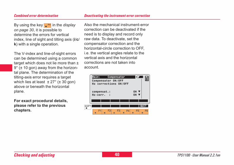
Also the mechanical instrument-errorcorrection can be deactivated if theneed is to display and record onlyraw data. To deactivate, set thecompensator correction and thehorizontal-circle correction to OFF,i.e. the vertical angles relate to thevertical axis and the horizontalcorrections are not taken intoaccount.
Deactivating the instrument-error correction
Main\ CompensatorCompensator ON/OFFHz corrections ON/OFF
compensat.: ONHz-corr. : ON
MC
QUIT
41TPS1100 - User Manual 2.2.1en Checking and adjusting
6
10
12
21
Sight the prism accurately with thecrosshair.
Starts the measuringprocedure.
Starts the calibration.
The two-axis compensator is turnedoff automatically when determiningthe ATR collimation error.This fact is shown by the symbol.
ATR collimation
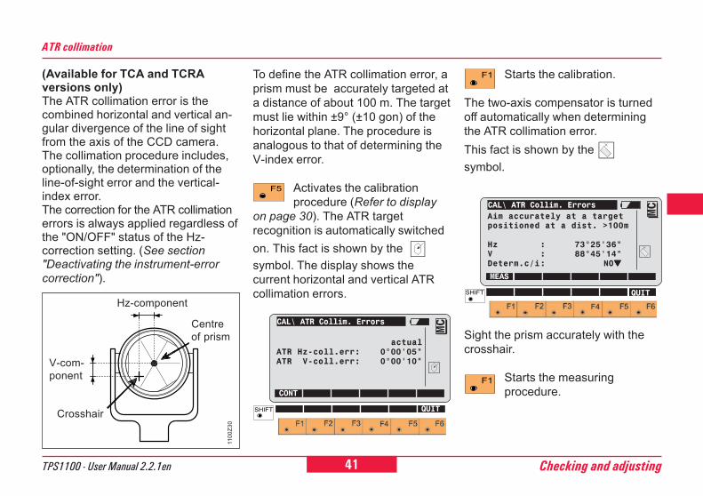
(Available for TCA and TCRAversions only)The ATR collimation error is thecombined horizontal and vertical an-gular divergence of the line of sightfrom the axis of the CCD camera.The collimation procedure includes,optionally, the determination of theline-of-sight error and the vertical-index error.The correction for the ATR collimationerrors is always applied regardless ofthe "ON/OFF" status of the Hz-correction setting. (See section"Deactivating the instrument-errorcorrection").
Centreof prism
Crosshair
V-com-ponent
Hz-component
To define the ATR collimation error, aprism must be accurately targeted ata distance of about 100 m. The targetmust lie within ±9° (±10 gon) of thehorizontal plane. The procedure isanalogous to that of determining theV-index error.
Activates the calibrationprocedure (Refer to display
on page 30). The ATR targetrecognition is automatically switchedon. This fact is shown by the symbol. The display shows thecurrent horizontal and vertical ATRcollimation errors.
CAL\ ATR Collim. Errors
actualATR Hz-coll.err: 0°00'05"ATR V-coll.err: 0°00'10"
CONT
MC
QUIT
1100
Z30
CAL\ ATR Collim. ErrorsAim accurately at a targetpositioned at a dist. >100m
Hz : 73°25'36"V : 88°45'14"Determ.c/i: NO▼▼▼▼▼
MEAS
MC
QUIT
42 TPS1100 - User Manual 2.2.1enChecking and adjusting
6
0
2
21
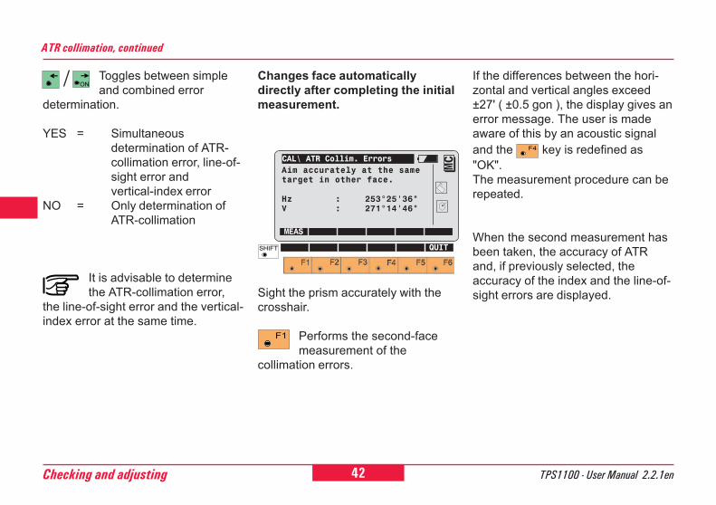
Toggles between simpleand combined error
determination.
YES = Simultaneousdetermination of ATR-collimation error, line-of-sight error andvertical-index error
NO = Only determination ofATR-collimation
It is advisable to determinethe ATR-collimation error,
the line-of-sight error and the vertical-index error at the same time.
If the differences between the hori-zontal and vertical angles exceed±27' ( ±0.5 gon ), the display gives anerror message. The user is madeaware of this by an acoustic signaland the key is redefined as"OK".The measurement procedure can berepeated.
When the second measurement hasbeen taken, the accuracy of ATRand, if previously selected, theaccuracy of the index and the line-of-sight errors are displayed.
ATR collimation, continued
Changes face automaticallydirectly after completing the initialmeasurement.
Sight the prism accurately with thecrosshair.
Performs the second-facemeasurement of the
collimation errors.
CAL\ ATR Collim. ErrorsAim accurately at the sametarget in other face.
Hz : 253°25'36"V : 271°14'46"
MEAS
MC
QUIT
43TPS1100 - User Manual 2.2.1en Checking and adjusting
6
10
12
21
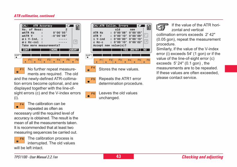
ATR collimation, continued
Stores the new values.
Repeats the ATR1 errordetermination procedure.
Leaves the old valuesunchanged.
No further repeat measure-ments are required. The old
and the newly-defined ATR-collima-tion errors become optional, and aredisplayed together with the line-of-sight errors (c) and the V-index errors(i).
The calibration can berepeated as often as
necessary until the required level ofaccuracy is obtained. The result is themean of all the measurements taken.It is recommended that at least twomeasuring sequences be carried out.
The calibration process isinterrupted. The old values
will be left intact.
If the value of the ATR hori-zontal and vertical
collimation errors exceeds 2' 42"(0.05 gon), repeat the measurementprocedure.Similarly, if the value of the V-indexerror (i) exceeds 54' (1 gon) or if thevalue of the line-of-sight error (c)exceeds 5' 24" (0.1 gon) , themeasurements are to be repeated.If these values are often exceeded,please contact service.
CAL\ ATR AccuracyNo. of Meas: 2σσσσσATR Hz : 0°00'05"σσσσσATR V : -0°00'08"σ σ σ σ σ i V-Ind. : -----σ σ σ σ σ c Hz-col : -----Take more measurements?
CONT MORE ABORT
MC
CAL\ATR Collim. Errors old new
ATR Hz : 0°00'08" 0°00'05"ATR V : 0°00'10" 0°00'09"i V-ind : 0°00'00" 0°00'10"c Hz-c : 0°00'10" 0°00'02"Accept new value(s)?
YES RETRY NO
MC
44 TPS1100 - User Manual 2.2.1enChecking and adjusting
6
0
2
21
Mechanically
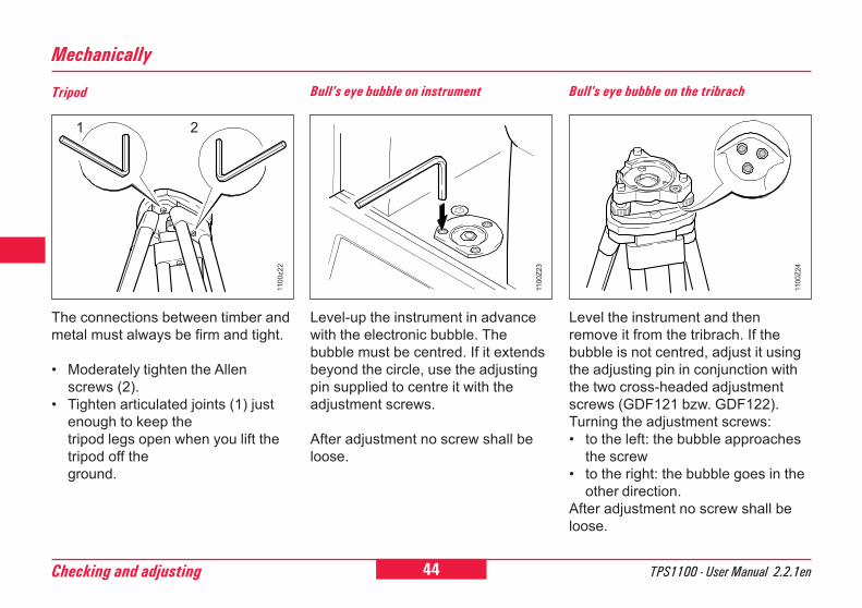
The connections between timber andmetal must always be firm and tight.
� Moderately tighten the Allenscrews (2).
� Tighten articulated joints (1) justenough to keep thetripod legs open when you lift thetripod off theground.
Tripod Bull's eye bubble on instrument
Level-up the instrument in advancewith the electronic bubble. Thebubble must be centred. If it extendsbeyond the circle, use the adjustingpin supplied to centre it with theadjustment screws.
After adjustment no screw shall beloose.
Bull's eye bubble on the tribrach
Level the instrument and thenremove it from the tribrach. If thebubble is not centred, adjust it usingthe adjusting pin in conjunction withthe two cross-headed adjustmentscrews (GDF121 bzw. GDF122).Turning the adjustment screws:� to the left: the bubble approaches
the screw� to the right: the bubble goes in the
other direction.After adjustment no screw shall beloose.
1 2
1100
Z23
1100
z22
1100
Z24

45TPS1100 - User Manual 2.2.1en Checking and adjusting
6
10
12
21
Checking by plumb-bob:
Optical plummet
Checking by turning the tribrach Adjustment
Set-up and level the instrument onthe tripod. Check the centring sleevefor eccentricity by hanging it in placein various positions, then mark theground point. Remove the plumb-bob. Check that the crosshairs of theoptical plummet intersect at theground point. The accuracyachievable is about 1mm.
Use a screwdriver to turn the two setscrews alternately by the same smallamount in order to centre thecrosshairs on the ground pointmarked.
Inspect the optical plummetof the tribrach regularly,
because any deviation of its line ofsight from the vertical axis will resultin a centring error.
1. Level-up the instrument using theelectronic bubble. Mark the groundpoint. Using a soft, well-sharpenedpencil, mark the outline of thetribrach on the tripod plate.
2. Turn the tribrach 120 ° and level-up the instrument, fit it into theoutline, and again mark the groundpoint.
3. Repeat again in the third position.
If the three points do not coincide,adjust the crosshairs to the centre ofthe triangle formed by the threeground points.
1100Z25
21 3
120° 120°
1100Z26
1100Z27
46 TPS1100 - User Manual 2.2.1enChecking and adjusting
6
0
2
21
Laser plummet
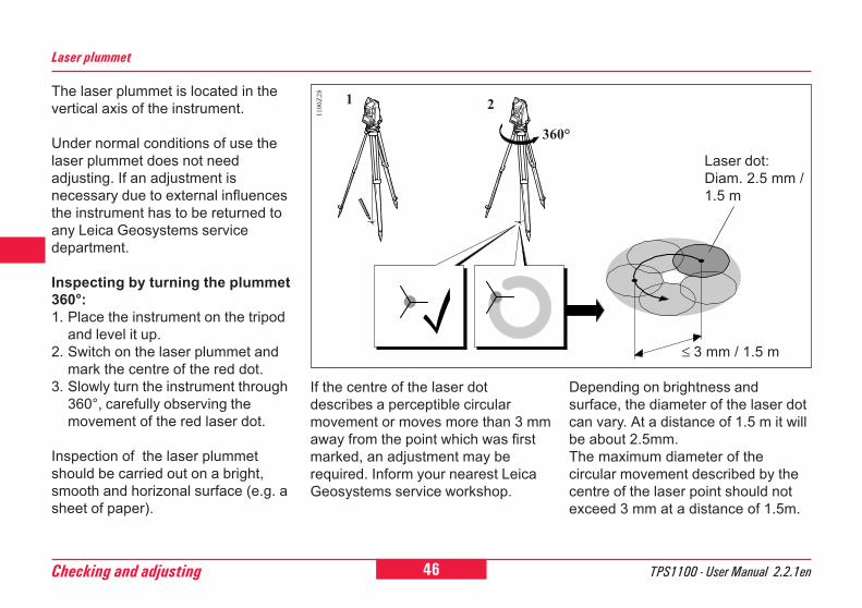
The laser plummet is located in thevertical axis of the instrument.
Under normal conditions of use thelaser plummet does not needadjusting. If an adjustment isnecessary due to external influencesthe instrument has to be returned toany Leica Geosystems servicedepartment.
Inspecting by turning the plummet360°:1. Place the instrument on the tripod
and level it up.2. Switch on the laser plummet and
mark the centre of the red dot.3. Slowly turn the instrument through
360°, carefully observing themovement of the red laser dot.
Inspection of the laser plummetshould be carried out on a bright,smooth and horizonal surface (e.g. asheet of paper).
Laser dot:Diam. 2.5 mm /1.5 m
If the centre of the laser dotdescribes a perceptible circularmovement or moves more than 3 mmaway from the point which was firstmarked, an adjustment may berequired. Inform your nearest LeicaGeosystems service workshop.
Depending on brightness andsurface, the diameter of the laser dotcan vary. At a distance of 1.5 m it willbe about 2.5mm.The maximum diameter of thecircular movement described by thecentre of the laser point should notexceed 3 mm at a distance of 1.5m.
360°
1100Z28
≤ 3 mm / 1.5 m
1 2
47TPS1100 - User Manual 2.2.1en Checking and adjusting
6
10
12
21
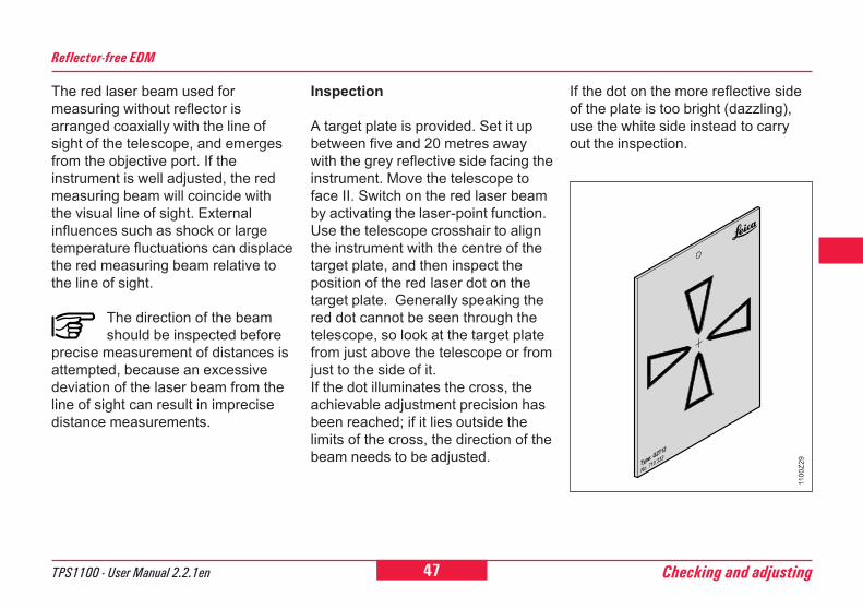
Inspection
A target plate is provided. Set it upbetween five and 20 metres awaywith the grey reflective side facing theinstrument. Move the telescope toface II. Switch on the red laser beamby activating the laser-point function.Use the telescope crosshair to alignthe instrument with the centre of thetarget plate, and then inspect theposition of the red laser dot on thetarget plate. Generally speaking thered dot cannot be seen through thetelescope, so look at the target platefrom just above the telescope or fromjust to the side of it.If the dot illuminates the cross, theachievable adjustment precision hasbeen reached; if it lies outside thelimits of the cross, the direction of thebeam needs to be adjusted.
Reflector-free EDM
The red laser beam used formeasuring without reflector isarranged coaxially with the line ofsight of the telescope, and emergesfrom the objective port. If theinstrument is well adjusted, the redmeasuring beam will coincide withthe visual line of sight. Externalinfluences such as shock or largetemperature fluctuations can displacethe red measuring beam relative tothe line of sight.
The direction of the beamshould be inspected before
precise measurement of distances isattempted, because an excessivedeviation of the laser beam from theline of sight can result in imprecisedistance measurements.
1100
Z29
If the dot on the more reflective sideof the plate is too bright (dazzling),use the white side instead to carryout the inspection.
48 TPS1100 - User Manual 2.2.1enChecking and adjusting
6
0
2
21
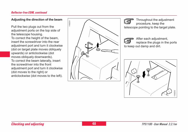
Adjusting the direction of the beam
Pull the two plugs out from theadjustment ports on the top side ofthe telescope housing.To correct the height of the beam,insert the screwdriver into the rearadjustment port and turn it clockwise(dot on target plate moves obliquelyupwards) or anticlockwise (dotmoves obliquely downwards).To correct the beam laterally, insertthe screwdriver into the frontadjustment port and turn it clockwise(dot moves to the right) oranticlockwise (dot moves to the left).
Reflector-free EDM, continued
Throughout the adjustmentprocedure, keep the
telescope pointing to the target plate.
After each adjustment,replace the plugs in the ports
to keep out damp and dirt.
1100
Z31
1100
Z32
49TPS1100 - User Manual 2.2.1en System functions
6
10
12
21
26
System functionsThis section describes the systemfunctions of the TPS1100instruments.The presentation of the dialogs, andthe sequence and names of theindividual functions, are inaccordance with the basic TPS1100configuration.
Data configuration
Data job (D JOB) and meas. job (M JOB)
A distinction is made between:� Input data, which are generally
fixed-point coordinates, and� Output data, which are generally
measurements, coordinates, orvalues derived from "new points."
It is useful to store the input data andthe output data in two separate files,although they can be stored togetherin one file.
Up to 60 files can be managed.The names of the files can bechosen freely, but the extension mustalways be GSI (e.g."PROJ2563.GSI").
In the directory \LOG, additional datafrom most of the loadableapplications can be stored in aprotocol file.
The data can be output in GSI formatto the serial interface instead of on tothe PC card.
If the data is stored on theserial interface, no data from
the applications will be output to theprotocol file. Fixed-point coordinatescan be read only from the PC card.
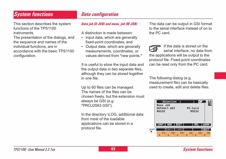
The following dialog (e.g.measurement file) can be basicallyused to create, edit and delete files.
\Selection ( )Meas JobDEFAULT.GSI PC-CardRS232 RS232
CONT NEW EDIT DEL αααααNUM
MC
|<<-- -->>| QUIT
50System functions TPS1100 - User Manual 2.2.1en
This function enables to create astandard codelist. Existing standardcodelists, point codelists and mixedcodelists can be edited, deleted andcopied. For the instrument torecognize the codelist and to accessit, the codelist must be saved underthe name *.CRF in the "CODE"directory.
The assignations of the keys, and thesubsequent course of the program,are the same as in the dialog "Meas.job", with the exception of the additio-nal function on (COPY).
CodelistData job (D JOB) and meas. job (M JOB), cont.
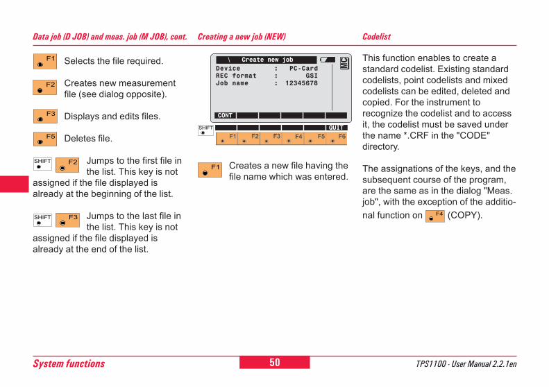
Selects the file required.
Creates new measurementfile (see dialog opposite).
Displays and edits files.
Deletes file.
Jumps to the first file inthe list. This key is not
assigned if the file displayed isalready at the beginning of the list.
Jumps to the last file inthe list. This key is not
assigned if the file displayed isalready at the end of the list.
Creating a new job (NEW)
\ Create new jobDevice : PC-CardREC format : GSIJob name : 12345678
CONT
MC
QUIT
Creates a new file having thefile name which was entered.
51TPS1100 - User Manual 2.2.1en System functions
6
10
12
21
26
Creating a new codelist (NEW)
\ New Codelist
Name of the new codelistName : 12345678
Device : Internal
CONT
MCQUIT
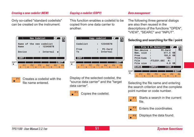
Only so-called "standard codelists"can be created on the instrument.
Copying a codelist (COPY)
This function enables a codelist to becopied from one data carrier toanother.
Display of the selected codelist, the"source data carrier" and the "targetdata carrier".
Copies the codelist.
Creates a codelist with thefile name entered.
\ Copy codelist
Codelist : 12345678
From : PC-CardTo : Internal
CONT
MC
QUIT
The following three general dialogsare also then reused in thedescriptions of the functions "OPEN","VIEW", "SEARC" and "INPUT".
Selecting and searching for file / point
Data management
\ File & Pt.SelectionRec.device : PC-CardMem. size : 511.5 KBFree : 193,0 KBPtId/Code : 100File :FILE01.GSI A:File size : 4.0 KB
SEARCH INPUT VIEW
MC
QUIT
Selecting the file name and enteringthe search criterion and the completepoint number or code number.
Starts a search in the currentfile.
Enters the coordinates.
Displays the data found.
52System functions TPS1100 - User Manual 2.2.1en
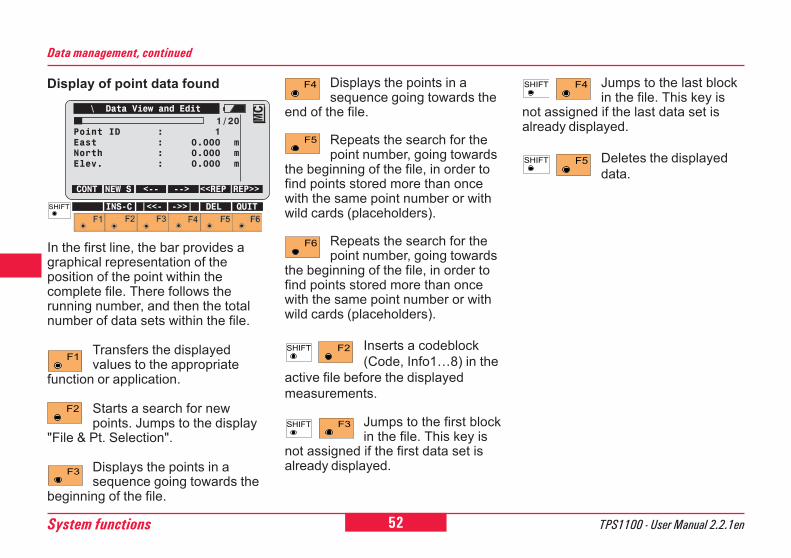
\ Data View and Edit1/20
Point ID : 1East : 0.000 mNorth : 0.000 mElev. : 0.000 m
CONT NEW S <-- --> <<REP REP>>
MC
INS-C |<<- ->>| DEL QUIT
Display of point data found
In the first line, the bar provides agraphical representation of theposition of the point within thecomplete file. There follows therunning number, and then the totalnumber of data sets within the file.
Transfers the displayedvalues to the appropriate
function or application.
Starts a search for newpoints. Jumps to the display
"File & Pt. Selection".
Displays the points in asequence going towards the
beginning of the file.
Displays the points in asequence going towards the
end of the file.
Repeats the search for thepoint number, going towards
the beginning of the file, in order tofind points stored more than oncewith the same point number or withwild cards (placeholders).
Repeats the search for thepoint number, going towards
the beginning of the file, in order tofind points stored more than oncewith the same point number or withwild cards (placeholders).
Inserts a codeblock(Code, Info1�8) in the
active file before the displayedmeasurements.
Jumps to the first blockin the file. This key is
not assigned if the first data set isalready displayed.
Data management, continued
Jumps to the last blockin the file. This key is
not assigned if the last data set isalready displayed.
Deletes the displayeddata.
53TPS1100 - User Manual 2.2.1en System functions
6
10
12
21
26
Number of GSI data found
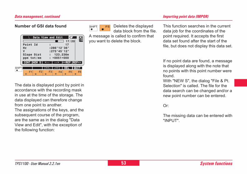
\ Data View and Edit17/20
Point Id : 17Hz :286°12'36"V :275°45'12"Slope Dist : 123.236mppm tot/mm : +0051+000
CONT NEW S <-- --> <<REP REP>>
MC
|<<- ->>| DEL QUIT
Data management, continued
The data is displayed point by point inaccordance with the recording maskin use at the time of the storage. Thedata displayed can therefore changefrom one point to another.The assignations of the keys, and thesubsequent course of the program,are the same as in the dialog "DataView and Edit", with the exception ofthe following function:
Deletes the displayeddata block from the file.
A message is called to confirm thatyou want to delete the block.
This function searches in the currentdata job for the coordinates of thepoint required. It accepts the firstdata set found after the start of thefile, but does not display this data set.
If no point data are found, a messageis displayed along with the note thatno points with this point number werefound.With "NEW S", the dialog "File & Pt.Selection" is called. The file for thedata search can be changed and/or anew point number can be entered.
Or:
The missing data can be entered with"INPUT".
Importing point data (IMPOR)
54System functions TPS1100 - User Manual 2.2.1en
This function searches in the currentdata job for the coordinates of therequired point. The first data setfound after the beginning of the file isthe one accepted. The data set foundis displayed in every case.
If point data are found, refer to thedialog "Data View and Edit". "CONT"accepts the values displayed, andterminates the function.
Or:
Using "NEW S", call the dialog "File& Pt. Selection". The file for the datasearch can be changed and/or a newpoint number can be entered.
Displaying and importing point data (VIEW)
If no point data is found, a messageappears with the note that no pointswith this point number were found.
Using "NEW S", call the dialog "File& Pt. Selection". The file for the datasearch can be changed and/or a newpoint number can be entered.
Or:
Using "INPUT", enter the missingdata.
This function searches in the currentmeasurement file for data relating tothe required point. The user has theoption of displaying the data storedon the PC-card within a chosen fileand to delete data blocks. Individualpoints, and multiple entries of pointswith the same point number, can besearched for, displayed and deleted.The last point number in the file isdisplayed automatically. If editing ofthe data is permitted, point numbers,code information, attributes,instrument height and reflector heightcan all be changed. Truemeasurement data such as directionsand distances cannot be changed.
To activate the dialog "File & Pt.Selection", refer to the appropriatedialog.
Displaying and editing GSI data (SEARC)
55TPS1100 - User Manual 2.2.1en System functions
6
10
12
21
26
If no point or code is found, amessage is displayed along with thenote that no point or code was foundin the current measurement file.
If a point or code is found, refer to thedialog "Data View and Edit".
Displaying GSI data, continued
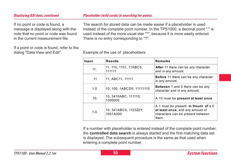
The search for stored data can be made easier if a placeholder is usedinstead of the complete point number. In the TPS1000, a decimal point "." isused instead of the more usual star "*", because it is more easily entered.There is no entry corresponding to "?".
Example of the use of placeholders:
If a number with placeholder is entered instead of the complete point number,the controlled data search is always started and the first matching data setis displayed. The subsequent procedure is the same as that used whenentering a complete point number.
Placeholder (wild cards) in searching for points
Input Results Remarks
11. 11, 110, 1101, 11ABC5,111111
After 11 there can be any characterand in any amount.
.11 11, ABC11, 11111 Before 11 there can be any characterin any amount.
1.0 10, 100, 1ABCD0, 11111110 Between 1 and 0 there can be anycharacter and in any amount.
.10. 10, 3410ABC, 111110,1000000 A 10 must be present at least once
.1.0. 10, 341ABC0, 1123Z0Y,1001A000
A 1 must be present in frount of a 0at least once, and any amount ofcharacters can be present betweenthem.
56System functions TPS1100 - User Manual 2.2.1en
Manual input of coordinates (INPUT)
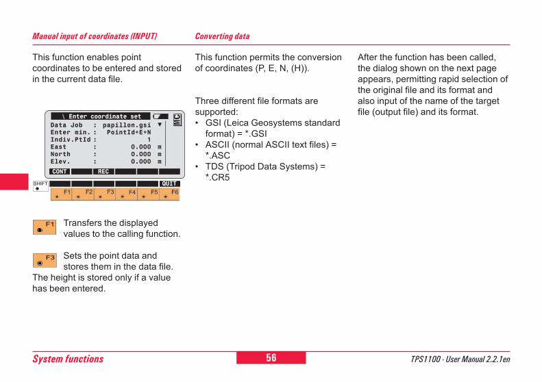
This function enables pointcoordinates to be entered and storedin the current data file.
\ Enter coordinate setData Job : papillon.gsiEnter min. : PointId+E+NIndiv.PtId : 1East : 0.000 mNorth : 0.000 mElev. : 0.000 m
CONT RECMC
QUIT
Transfers the displayedvalues to the calling function.
Sets the point data andstores them in the data file.
The height is stored only if a valuehas been entered.
This function permits the conversionof coordinates (P, E, N, (H)).
Three different file formats aresupported:� GSI (Leica Geosystems standard
format) = *.GSI� ASCII (normal ASCII text files) =
*.ASC� TDS (Tripod Data Systems) =
*.CR5
Converting data
After the function has been called,the dialog shown on the next pageappears, permitting rapid selection ofthe original file and its format andalso input of the name of the targetfile (output file) and its format.
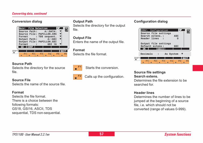
57TPS1100 - User Manual 2.2.1en System functions
6
10
12
21
26
Conversion dialog
Main\ File SelectionSource Path: A:\DATA\Source File: PAPILLON.CR5Format : TDS sequent.Output Path: A:\GSIOutput File: PAPILLON.GSIFormat : GSI 16GO CONF
MC
QUIT
Source PathSelects the directory for the sourcefile.
Source FileSelects the name of the source file.
FormatSelects the file format.There is a choice between thefollowing formats:GS18, GSI16, ASCII, TDSsequential, TDS non-sequential.
Converting data, continued
Configuration dialog
Source file settingsSearch extens.Determines the file extension to besearched for.
Header linesDetermines the number of lines to bejumped at the beginning of a sourcefile, i.e. which should not beconverted (range of values 0-999).
Output PathSelects the directory for the outputfile.
Output FileEnters the name of the output file.
FormatSelects the file format.
Starts the conversion.
Calls up the configuration.
CONV\ ConfigurationSource file settingsSearch extens. : ASCHeader lines : 0
Output file settingsDefault extens : GSIOK ASCII
MC
QUIT
Decimals : As System
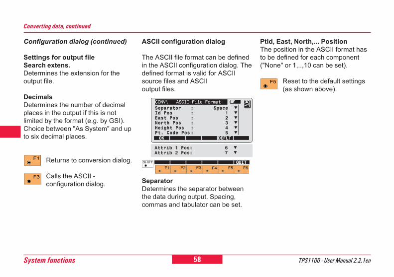
58System functions TPS1100 - User Manual 2.2.1en
Converting data, continued
Configuration dialog (continued)
Settings for output fileSearch extens.Determines the extension for theoutput file.
DecimalsDetermines the number of decimalplaces in the output if this is notlimited by the format (e.g. by GSI).Choice between "As System" and upto six decimal places.
Returns to conversion dialog.
Calls the ASCII -configuration dialog.
ASCII configuration dialog
The ASCII file format can be definedin the ASCII configuration dialog. Thedefined format is valid for ASCIIsource files and ASCIIoutput files.
SeparatorDetermines the separator betweenthe data during output. Spacing,commas and tabulator can be set.
PtId, East, North,... PositionThe position in the ASCII format hasto be defined for each component("None" or 1,..,10 can be set).
Reset to the default settings(as shown above).
CONV\ ASCII File FormatSeparator : SpaceId Pos : 1East Pos : 2North Pos : 3Height Pos : 4Pt. Code Pos: 5OK DEFLT
MC
QUIT
Attrib 1 Pos: 6Attrib 2 Pos: 7
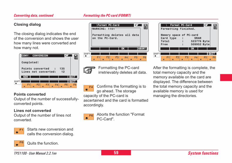
59TPS1100 - User Manual 2.2.1en System functions
6
10
12
21
26
Closing dialog
The closing dialog indicates the endof the conversion and shows the userhow many lines were converted andhow many not.
CONV\ CONVERSION
Completed!
Points converted : 135Lines not converted: 12
NEW QUITMC
QUIT
Points convertedOutput of the number of successfully-converted points.
Lines not convertedOutput of the number of lines notconverted.
Starts new conversion andcalls the conversion dialog.
Quits the function.
Converting data, continued Formatting the PC-card (FORMT)
\Format PC-CardWARNING: 1151
Formatting deletes all dataon the PC-Card.
OK ABORT
MC
Formatting the PC-cardirretrievably deletes all data.
Confirms the formatting is togo ahead. The storage
capacity of the PC-card isascertained and the card is formattedaccordingly.
Aborts the function "FormatPC-Card".
\ Format PC-CardFormatting finished.
Memory space of PC-cardCard type : SRAMTotal : 523776 ByteFree : 509952 Byte
OK
MC
QUIT
After the formatting is complete, thetotal memory capacity and thememory available on the card aredisplayed. The difference betweenthe total memory capacity and theavailable memory is used formanaging the directories.
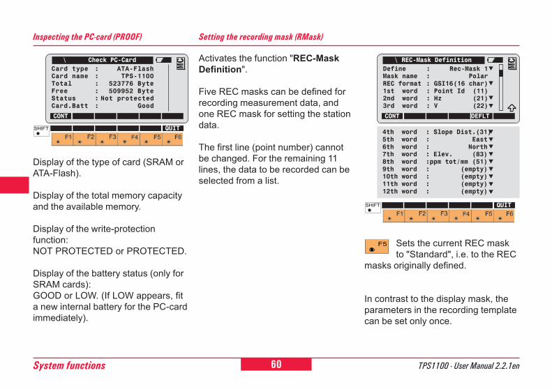
60System functions TPS1100 - User Manual 2.2.1en
Activates the function "REC-MaskDefinition".
Five REC masks can be defined forrecording measurement data, andone REC mask for setting the stationdata.
The first line (point number) cannotbe changed. For the remaining 11lines, the data to be recorded can beselected from a list.
Setting the recording mask (RMask)
Sets the current REC maskto "Standard", i.e. to the REC
masks originally defined.
In contrast to the display mask, theparameters in the recording templatecan be set only once.
\ REC-Mask DefinitionDefine : Rec-Mask 1Mask name : PolarREC format : GSI16(16 char)1st word : Point Id (11)2nd word : Hz (21)3rd word : V (22)
CONT DEFLT
MC
QUIT
4th word : Slope Dist.(31)5th word : East6th word : North7th word : Elev. (83)8th word :ppm tot/mm (51)9th word : (empty)10th word : (empty)11th word : (empty)12th word : (empty)
Display of the type of card (SRAM orATA-Flash).
Display of the total memory capacityand the available memory.
Display of the write-protectionfunction:NOT PROTECTED or PROTECTED.
Display of the battery status (only forSRAM cards):GOOD or LOW. (If LOW appears, fita new internal battery for the PC-cardimmediately).
Inspecting the PC-card (PROOF)
\ Check PC-CardCard type : ATA-FlashCard name : TPS-1100Total : 523776 ByteFree : 509952 ByteStatus : Not protectedCard.Batt : Good
CONT
MC
QUIT
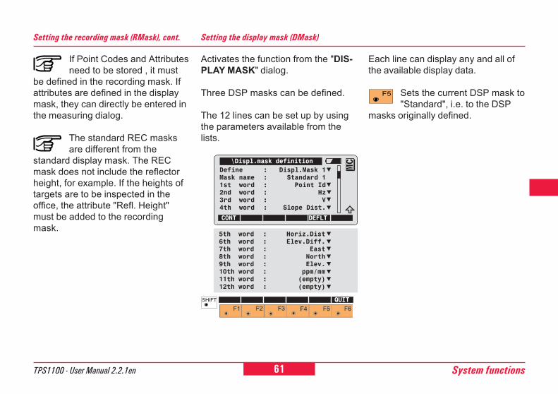
61TPS1100 - User Manual 2.2.1en System functions
6
10
12
21
26
If Point Codes and Attributesneed to be stored , it must
be defined in the recording mask. Ifattributes are defined in the displaymask, they can directly be entered inthe measuring dialog.
The standard REC masksare different from the
standard display mask. The RECmask does not include the reflectorheight, for example. If the heights oftargets are to be inspected in theoffice, the attribute "Refl. Height"must be added to the recordingmask.
Setting the recording mask (RMask), cont.
Activates the function from the "DIS-PLAY MASK" dialog.
Three DSP masks can be defined.
The 12 lines can be set up by usingthe parameters available from thelists.
Setting the display mask (DMask)
Each line can display any and all ofthe available display data.
Sets the current DSP mask to"Standard", i.e. to the DSP
masks originally defined.
\Displ.mask definitionDefine : Displ.Mask 1Mask name : Standard 11st word : Point Id2nd word : Hz3rd word : V4th word : Slope Dist.
CONT DEFLT
MC
5th word : Horiz.Dist6th word : Elev.Diff.7th word : East8th word : North9th word : Elev.10th word : ppm/mm11th word : (empty)12th word : (empty)
QUIT
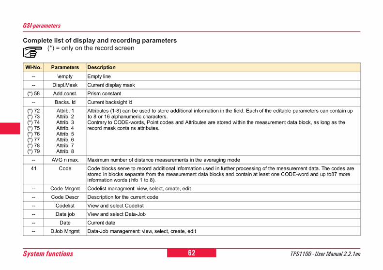
62System functions TPS1100 - User Manual 2.2.1en
GSI-parameters
WI-No. Parameters Description-- \empty Empty line-- Displ.Mask Current display mask
(*) 58 Add.const. Prism constant-- Backs. Id Current backsight Id
(*) 72(*) 73(*) 74(*) 75(*) 76(*) 77(*) 78(*) 79
Attrib. 1Attrib. 2Attrib. 3Attrib. 4Attrib. 5Attrib. 6Attrib. 7Attrib. 8
Attributes (1-8) can be used to store additional information in the field. Each of the editable parameters can contain upto 8 or 16 alphanumeric characters.Contrary to CODE-words, Point codes and Attributes are stored within the measurement data block, as long as therecord mask contains attributes.
-- AVG n max. Maximum number of distance measurements in the averaging mode41 Code Code blocks serve to record additional information used in further processing of the measurement data. The codes are
stored in blocks separate from the measurement data blocks and contain at least one CODE-word and up to87 moreinformation words (Info 1 to 8).
-- Code Mngmt Codelist managment: view, select, create, edit-- Code Descr Description for the current code-- Codelist View and select Codelist-- Data job View and select Data-Job-- Date Current date-- DJob Mngmt Data-Job management: view, select, create, edit
Complete list of display and recording parameters(*) = only on the record screen
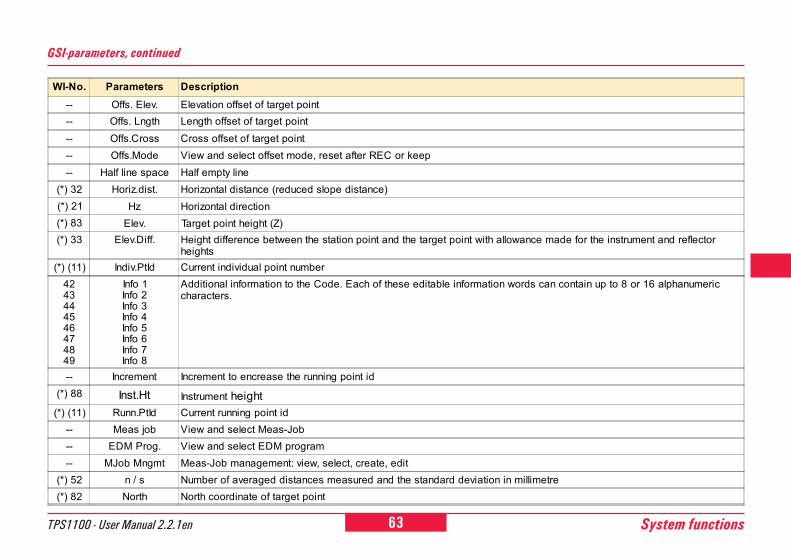
63TPS1100 - User Manual 2.2.1en System functions
6
10
12
21
26
WI-No. Parameters Description-- Offs. Elev. Elevation offset of target point-- Offs. Lngth Length offset of target point-- Offs.Cross Cross offset of target point-- Offs.Mode View and select offset mode, reset after REC or keep-- Half line space Half empty line
(*) 32 Horiz.dist. Horizontal distance (reduced slope distance)(*) 21 Hz Horizontal direction(*) 83 Elev. Target point height (Z)(*) 33 Elev.Diff. Height difference between the station point and the target point with allowance made for the instrument and reflector
heights(*) (11) Indiv.PtId Current individual point number
4243444546474849
Info 1Info 2Info 3Info 4Info 5Info 6Info 7Info 8
Additional information to the Code. Each of these editable information words can contain up to 8 or 16 alphanumericcharacters.
-- Increment Increment to encrease the running point id(*) 88 Inst.Ht Instrument height(*) (11) Runn.PtId Current running point id
-- Meas job View and select Meas-Job-- EDM Prog. View and select EDM program-- MJob Mngmt Meas-Job management: view, select, create, edit
(*) 52 n / s Number of averaged distances measured and the standard deviation in millimetre(*) 82 North North coordinate of target point
GSI-parameters, continued
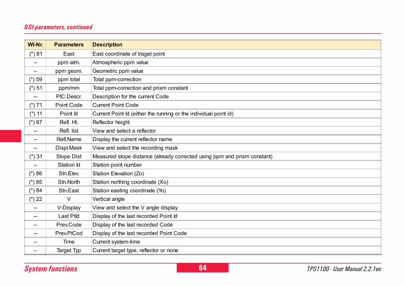
64System functions TPS1100 - User Manual 2.2.1en
GSI-parameters, continued
WI-Nr. Parameters Description(*) 81 East East coordinate of traget point
-- ppm atm. Atmospheric ppm value-- ppm geom. Geometric ppm value
(*) 59 ppm total Total ppm-correction(*) 51 ppm/mm Total ppm-correction and prism constant
-- PtC.Descr. Description for the current Code(*) 71 Point Code Current Point Code(*) 11 Point Id Current Point Id (either the running or the individual point id)(*) 87 Refl. Ht. Reflector height
-- Refl. list View and select a reflector-- Refl.Name Display the current reflector name-- Displ.Mask View and select the recording mask
(*) 31 Slope Dist Measured slope distance (already corrected using ppm and prism constant)-- Station Id Station point number
(*) 86 Stn.Elev. Station Elevation (Zo)(*) 85 Stn.North Station northing coordinate (Xo)(*) 84 Stn.East Station easting coordinate (Yo)(*) 22 V Vertical angle
-- V-Display View and select the V angle display-- Last PtId Display of the last recorded Point Id-- Prev.Code Display of the last recorded Code-- Prev.PtCod Display of the last recorded Point Code-- Time Current system-time-- Target Typ Current target type, reflector or none
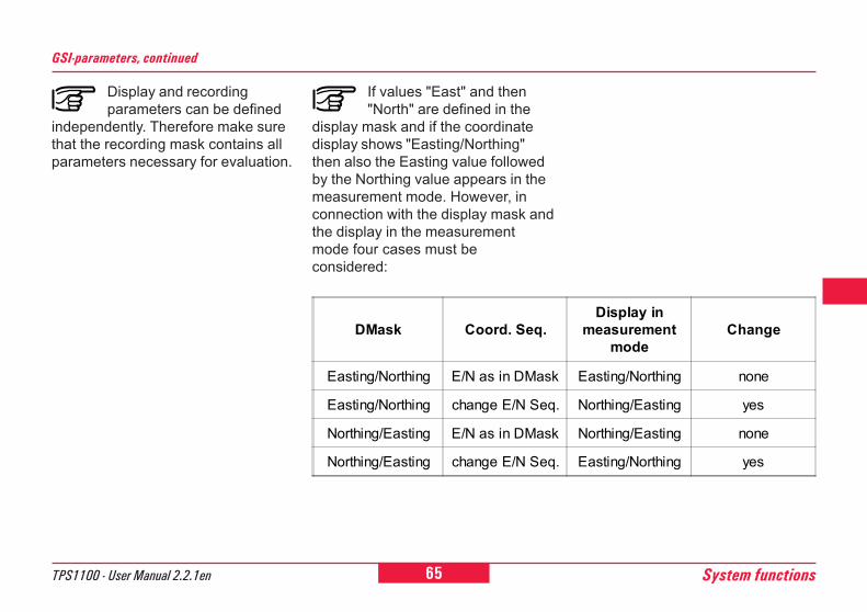
65TPS1100 - User Manual 2.2.1en System functions
6
10
12
21
26
Display and recordingparameters can be defined
independently. Therefore make surethat the recording mask contains allparameters necessary for evaluation.
GSI-parameters, continued
If values "East" and then"North" are defined in the
display mask and if the coordinatedisplay shows "Easting/Northing"then also the Easting value followedby the Northing value appears in themeasurement mode. However, inconnection with the display mask andthe display in the measurementmode four cases must beconsidered:
DMask Coord. Seq.Display in
measurementmode
Change
Easting/Northing E/N as in DMask Easting/Northing none
Easting/Northing change E/N Seq. Northing/Easting yes
Northing/Easting E/N as in DMask Northing/Easting none
Northing/Easting change E/N Seq. Easting/Northing yes
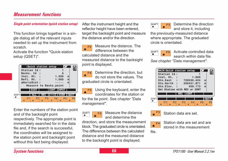
66System functions TPS1100 - User Manual 2.2.1en
After the instrument height and thereflector height have been entered,target the backsight point and measurethe distance and/or the direction.
Measure the distance. Thedifference between the
calculated distance and themeasured distance to the backsightpoint is displayed.
Determine the direction, butdo not store the values. The
graduated circle is orientated.
Using the keyboard, enter thecoordinates for the station or
for the tie point. See chapter "Datamanagement".
Measure the distanceand determine the
direction, and store the measurementblock. The graduated circle is orientated.The difference between the calculateddistance and the measured distanceto the backsight point is displayed.
Single-point orientation (quick station setup)
This function brings together in a sin-gle dialog all of the relevant inputsneeded to set up the instrument fromscratch.Activate the function "Quick-stationsetup (QSET)".
Enter the numbers of the station pointand of the backsight pointrespectively. The appropriate point isimmediately searched for in the datafile and, if the search is successful,the coordinates will be assigned tothe station point and backsight pointwithout this fact being displayed.
\Quick station setupStation Id : 1Backs. Id : AInst. Ht. : 1.500 mRefl. Ht. : 1.000 m∆∆∆∆∆HorizDist : ----- m Measure to Backs.point
DIST CONT INPUT
MC
ALL REC I<>II VIEW QUIT
MAIN\Quick station setupStation Id : 1Inst. Ht. : 1.600Stn.East : 726530.424 mStn.North : 256431.871 mStn.Elev. : 459.173 mSet Station with REC or CONT
REC CONT
MC
QUIT
Station data are set.
Station data are set and arestored in the measurement
file.
Measurement functions
Determine the directionand store it, including
the previously-measured distancewhere appropriate. The graduatedcircle is orientated.
Activate controlled datasearch within data file.
See chapter "Data management".
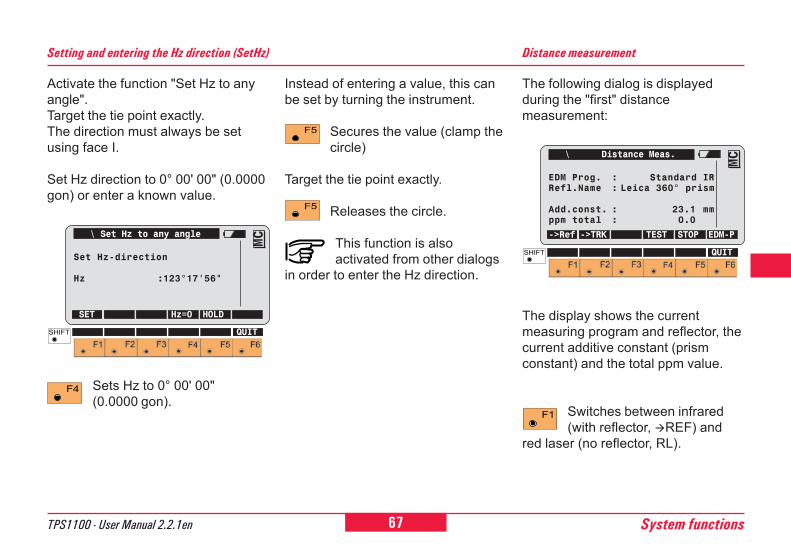
67TPS1100 - User Manual 2.2.1en System functions
6
10
12
21
26
Setting and entering the Hz direction (SetHz)
Activate the function "Set Hz to anyangle".Target the tie point exactly.The direction must always be setusing face I.
Set Hz direction to 0° 00' 00" (0.0000gon) or enter a known value.
Sets Hz to 0° 00' 00"(0.0000 gon).
Instead of entering a value, this canbe set by turning the instrument.
Secures the value (clamp thecircle)
Target the tie point exactly.
Releases the circle.
This function is alsoactivated from other dialogs
in order to enter the Hz direction.
Distance measurement
The following dialog is displayedduring the "first" distancemeasurement:
\ Set Hz to any angle
Set Hz-direction
Hz :123°17'56"
SET Hz=0 HOLD
MC
QUIT
\ Distance Meas.
EDM Prog. : Standard IRRefl.Name : Leica 360° prism
Add.const. : 23.1 mmppm total : 0.0
->Ref ->TRK TEST STOP EDM-P
MC
QUIT
The display shows the currentmeasuring program and reflector, thecurrent additive constant (prismconstant) and the total ppm value.
Switches between infrared(with reflector, !REF) and
red laser (no reflector, RL).
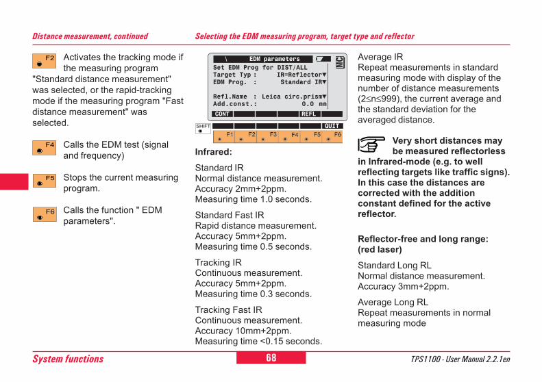
68System functions TPS1100 - User Manual 2.2.1en
Activates the tracking mode ifthe measuring program
"Standard distance measurement"was selected, or the rapid-trackingmode if the measuring program "Fastdistance measurement" wasselected.
Calls the EDM test (signaland frequency)
Stops the current measuringprogram.
Calls the function " EDMparameters".
Distance measurement, continued Selecting the EDM measuring program, target type and reflector
\ EDM parametersSet EDM Prog for DIST/ALLTarget Typ : IR=ReflectorEDM Prog. : Standard IR
Refl.Name : Leica circ.prismAdd.const.: 0.0 mm
CONT REFL
MC
QUIT
Infrared:Standard IRNormal distance measurement.Accuracy 2mm+2ppm.Measuring time 1.0 seconds.
Standard Fast IRRapid distance measurement.Accuracy 5mm+2ppm.Measuring time 0.5 seconds.
Tracking IRContinuous measurement.Accuracy 5mm+2ppm.Measuring time 0.3 seconds.
Tracking Fast IRContinuous measurement.Accuracy 10mm+2ppm.Measuring time <0.15 seconds.
Average IRRepeat measurements in standardmeasuring mode with display of thenumber of distance measurements(2≤n≤999), the current average andthe standard deviation for theaveraged distance.
Very short distances maybe measured reflectorless
in Infrared-mode (e.g. to wellreflecting targets like traffic signs).In this case the distances arecorrected with the additionconstant defined for the activereflector.
Reflector-free and long range:(red laser)Standard Long RLNormal distance measurement.Accuracy 3mm+2ppm.
Average Long RLRepeat measurements in normalmeasuring mode
69TPS1100 - User Manual 2.2.1en System functions
6
10
12
21
26
Selecting the EDM ..., continued
Selecting the target type
This line appears only if areflectorless instrument is beingused. There is a choice between"reflectorless" and "reflector".
Wrong target type settingleads to bad measurements.
Refl.Name
The current reflector is indicated and,on the next line, the additive constantassociated with it.
Calls the function "Reflectorselection".
Wrong prism setting leads tobad measurements.
Switch between IR/RL
[ >REF ] Activates infrareddistance measurement(with reflector). The lastused ATR/LOCKsettings aresimultaneouslyactivated.
[ >RL ] Activates reflectorlessdistance measurement.
WARNING:(only for Extended RangeInstruments)
Reflector-free:The visible laser beam may only beused within a controlled area (refer tochapter "Safety Directions") and musthit a non reflecting material at theend of its intended path.Long Range to prisms:This mode is only permissible from adistance of 1000 m (3300 ft) from thetelescope. No persons may staywithin the beam path up to 1000 m(=controlled area; refer to chapter"Safety Directions").
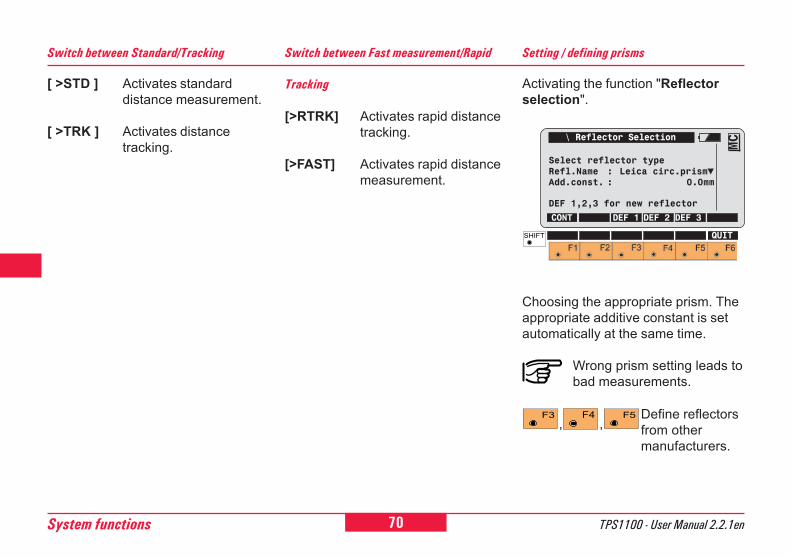
70System functions TPS1100 - User Manual 2.2.1en
Setting / defining prisms
Activating the function "Reflectorselection".
Choosing the appropriate prism. Theappropriate additive constant is setautomatically at the same time.
Wrong prism setting leads tobad measurements.
\ Reflector Selection
Select reflector typeRefl.Name : Leica circ.prismAdd.const. : 0.0mm
DEF 1,2,3 for new reflector
CONT DEF 1 DEF 2 DEF 3
MC
QUIT
Define reflectorsfrom othermanufacturers.
, ,
[>RTRK] Activates rapid distancetracking.
[>FAST] Activates rapid distancemeasurement.
Tracking
Switch between Fast measurement/RapidSwitch between Standard/Tracking
[ >STD ] Activates standarddistance measurement.
[ >TRK ] Activates distancetracking.
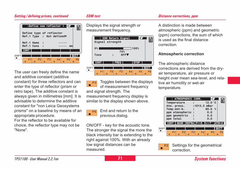
71TPS1100 - User Manual 2.2.1en System functions
6
10
12
21
26
EDM test
Toggles between the displaysof measurement frequency
and signal strength. Themeasurement frequency display issimilar to the display shown above.
End and return to theprevious dialog.
ON/OFF - key for the acoustic tone.The stronger the signal the more theblack intensity bar is extending to theright against 100%. With an alreadylow signal distances can bemeasured.
Displays the signal strength ormeasurement frequency.
\ EDM Return SignalSignal strength
0% 100%75%
Tone : OFF▼▼▼▼▼
CONT FREQ STOP
MC
QUIT
Distance corrections, ppm
A distinction is made betweenatmospheric (ppm) and geometric(ppm) corrections, the sum of whichis used as the final distancecorrection.
Settings for the geometricalcorrection.
Atmospheric correction
The atmospheric distancecorrections are derived from the dry-air temperature, air pressure orheight over mean sea-level, and rela-tive air humidity or wet-airtemperature.
\ ATMOSPHERIC CORR.Temperature : 12.0 °CAtm. press. :1013.3 mBarTemp.wet-b. : 60.0 %ppm atmospheric : 0.0ppm geometric : 0.0ppm total : 0.0
CONT GEOM REFRA P<>E %<>T' ATM=0
MC
QUIT
The user can freely define the nameand additive constant (additiveconstant) for three reflectors and canenter the type of reflector (prism orretro tape). The additive constant isalways given in millimetres [mm]. It isadvisable to determine the additiveconstant for "non Leica Geosystemsprisms" on a baseline by means of anappropriate procedure.For the reflector to be available forchoice, the reflector type may not be"None".
\Define new reflector 1
Define type of reflectorRef.1 Type : Not defined
Ref.1 Name : -----Ref.1 Cons : ----- mm
CONT
MC
QUIT
Setting / defining prisms, continued
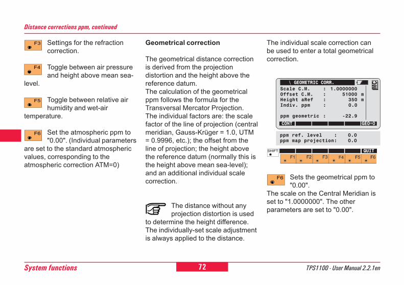
72System functions TPS1100 - User Manual 2.2.1en
Sets the geometrical ppm to"0.00".
The scale on the Central Meridian isset to "1.0000000". The otherparameters are set to "0.00".
The individual scale correction canbe used to enter a total geometricalcorrection.
\ GEOMETRIC CORR.Scale C.M. : 1.0000000Offset C.M. : 51000 mHeight aRef : 350 mIndiv. ppm : 0.0
ppm geometric : -22.9
CONT GEO=0
MC
QUIT
ppm ref. level : 0.0ppm map projection: 0.0
Distance corrections ppm, continued
Geometrical correction
The geometrical distance correctionis derived from the projectiondistortion and the height above thereference datum.The calculation of the geometricalppm follows the formula for theTransversal Mercator Projection.The individual factors are: the scalefactor of the line of projection (centralmeridian, Gauss-Krüger = 1.0, UTM= 0.9996, etc.); the offset from theline of projection; the height abovethe reference datum (normally this isthe height above mean sea-level);and an additional individual scalecorrection.
The distance without anyprojection distortion is used
to determine the height difference.The individually-set scale adjustmentis always applied to the distance.
Settings for the refractioncorrection.
Toggle between air pressureand height above mean sea-
level.
Toggle between relative airhumidity and wet-air
temperature.
Set the atmospheric ppm to"0.00". (Individual parameters
are set to the standard atmosphericvalues, corresponding to theatmospheric correction ATM=0)
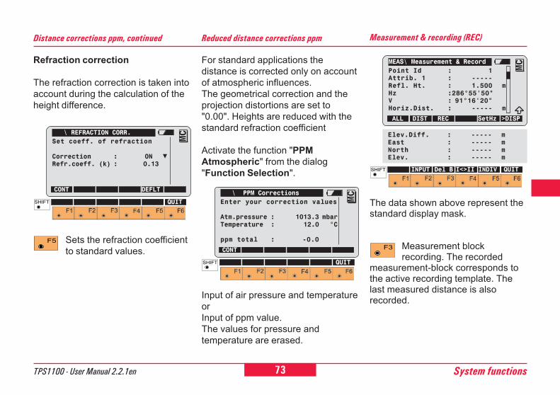
73TPS1100 - User Manual 2.2.1en System functions
6
10
12
21
26
Reduced distance corrections ppm
For standard applications thedistance is corrected only on accountof atmospheric influences.The geometrical correction and theprojection distortions are set to"0.00". Heights are reduced with thestandard refraction coefficient
Activate the function "PPMAtmospheric" from the dialog"Function Selection".
Input of air pressure and temperatureorInput of ppm value.The values for pressure andtemperature are erased.
\ PPM CorrectionsEnter your correction values
Atm.pressure : 1013.3 mbarTemperature : 12.0 °C
ppm total : -0.0
CONT
MC
QUIT
Refraction correction
The refraction correction is taken intoaccount during the calculation of theheight difference.
Sets the refraction coefficientto standard values.
Distance corrections ppm, continued
\ REFRACTION CORR.Set coeff. of refraction
Correction : ONRefr.coeff. (k) : 0.13
CONT DEFLTMC
QUIT
Measurement & recording (REC)
MEAS\ Measurement & RecordPoint Id : 1Attrib. 1 : -----Refl. Ht. : 1.500 mHz :286°55'50"V : 91°16'20"Horiz.Dist. : ----- m
ALL DIST REC SetHz >DISP
MC
INPUT Del B I<>II INDIV QUIT
Elev.Diff. : ----- mEast : ----- mNorth : ----- mElev. : ----- m
The data shown above represent thestandard display mask.
Measurement blockrecording. The recorded
measurement-block corresponds tothe active recording template. Thelast measured distance is alsorecorded.
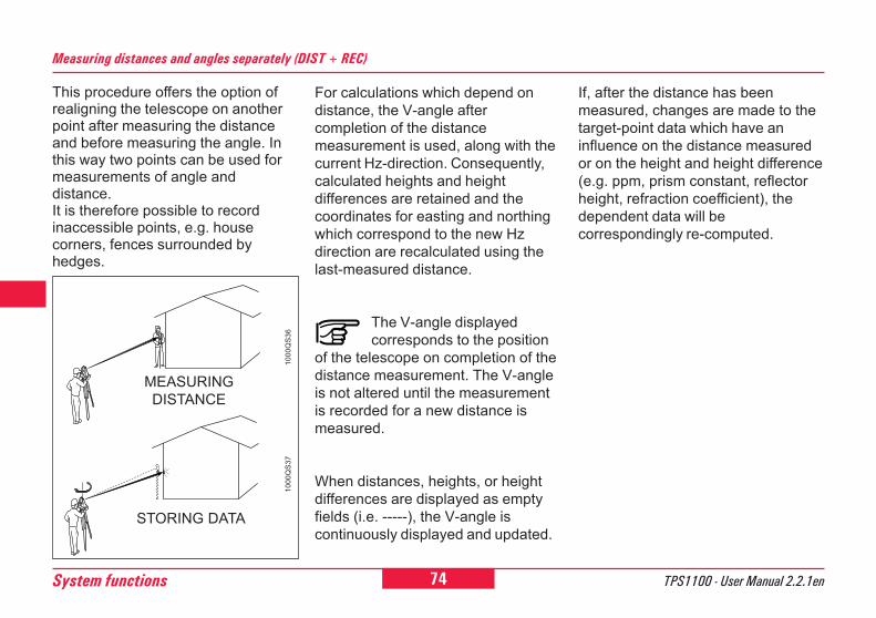
74System functions TPS1100 - User Manual 2.2.1en
Measuring distances and angles separately (DIST + REC)
This procedure offers the option ofrealigning the telescope on anotherpoint after measuring the distanceand before measuring the angle. Inthis way two points can be used formeasurements of angle anddistance.It is therefore possible to recordinaccessible points, e.g. housecorners, fences surrounded byhedges.
STORING DATA
MEASURINGDISTANCE
1000
QS
3610
00Q
S37
For calculations which depend ondistance, the V-angle aftercompletion of the distancemeasurement is used, along with thecurrent Hz-direction. Consequently,calculated heights and heightdifferences are retained and thecoordinates for easting and northingwhich correspond to the new Hzdirection are recalculated using thelast-measured distance.
The V-angle displayedcorresponds to the position
of the telescope on completion of thedistance measurement. The V-angleis not altered until the measurementis recorded for a new distance ismeasured.
When distances, heights, or heightdifferences are displayed as emptyfields (i.e. -----), the V-angle iscontinuously displayed and updated.
If, after the distance has beenmeasured, changes are made to thetarget-point data which have aninfluence on the distance measuredor on the height and height difference(e.g. ppm, prism constant, reflectorheight, refraction coefficient), thedependent data will becorrespondingly re-computed.
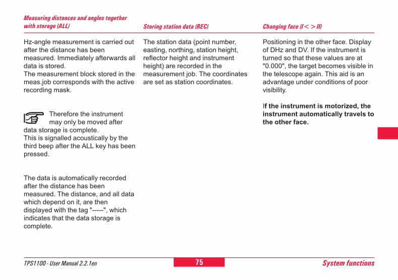
75TPS1100 - User Manual 2.2.1en System functions
6
10
12
21
26
Hz-angle measurement is carried outafter the distance has beenmeasured. Immediately afterwards alldata is stored.The measurement block stored in themeas.job corresponds with the activerecording mask.
Therefore the instrumentmay only be moved after
data storage is complete.This is signalled acoustically by thethird beep after the ALL key has beenpressed.
The data is automatically recordedafter the distance has beenmeasured. The distance, and all datawhich depend on it, are thendisplayed with the tag "-----", whichindicates that the data storage iscomplete.
Measuring distances and angles togetherwith storage (ALL) Storing station data (REC)
The station data (point number,easting, northing, station height,reflector height and instrumentheight) are recorded in themeasurement job. The coordinatesare set as station coordinates.
Changing face (I<>II)
Positioning in the other face. Displayof DHz and DV. If the instrument isturned so that these values are at"0.000", the target becomes visible inthe telescope again. This aid is anadvantage under conditions of poorvisibility.
If the instrument is motorized, theinstrument automatically travels tothe other face.
76System functions TPS1100 - User Manual 2.2.1en
Enter the last point number to bestored and use it as the current pointnumber.
Last point number (L.Pt.)
This function deletes the last GSIblock of the current measuring job.With "Del B", a measuring block(starting with WI11) or a code block(starting with WI41) can be deleted.
Deleting the GSI block (Del B) Manual distance entry
Enter the horizontal distance, whichwas measured with a tape forinstance.Immediately after confirmation ofinput, the horizontal distance isshown corrected for the geometricalppm. After the distance has beenentered, the V-angle is set to "hori-zontal" 90° ( 100 gon ) or 270° ( 300gon ). The coordinates are calculatedusing the corrected horizontaldistance, the Hz-direction, and the V-angle. Heights are always correctedfor earth curvature and are correctedfor refraction according to theparameter settings.
The reflector height istemporarily set to the value
for the instrument height and so thereis always a height difference of"0.000".The slope distance is the same asthe horizontal distance.
77TPS1100 - User Manual 2.2.1en System functions
6
10
12
21
26
(Applies only to motorizedinstruments)
The telescope is automaticallypointed at the latest point to bestored. This function is available onlyif a point was stored after switchingon the instrument.
Positioning the last point stored (LAST)
[>FREE] This function activatesthe vertical angle mode"Running" for thefollowing measurements.In this mode, the verticalangle is continuouslyupdated with thetelescope movement.
After a distancemeasurement, vertical angle,
slope distance, height difference, andthe elevation coordinate aredisplayed as running values. Slopedistance, height difference, and theelevation coordinate of the targetpoint are calculated from the initialhorizontal distance and currentlydisplayed vertical angle. The REC-function records the displayed valuesin the measurement file.
V-angle modes
[>FIX] This function activatesthe vertical angle mode"Hold after DIST" for thefollowingmeasurements. In thismode, the vertical angleis fixed after a distancemeasurement, whereasthe horizontal angle isrunning.
Function [VRUN]
This function deletes the lastmeasured distance and so releasesthe locked vertical angle.
(Available only with specialconfiguration.)
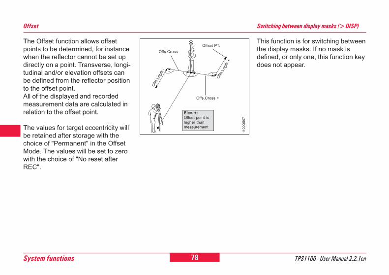
78System functions TPS1100 - User Manual 2.2.1en
This function is for switching betweenthe display masks. If no mask isdefined, or only one, this function keydoes not appear.
Switching between display masks (>DISP)Offset
The Offset function allows offsetpoints to be determined, for instancewhen the reflector cannot be set updirectly on a point. Transverse, longi-tudinal and/or elevation offsets canbe defined from the reflector positionto the offset point.All of the displayed and recordedmeasurement data are calculated inrelation to the offset point.
The values for target eccentricity willbe retained after storage with thechoice of "Permanent" in the OffsetMode. The values will be set to zerowith the choice of "No reset afterREC".
1100
QS
07
Offs
.Lng
th -
Offs.Cross -
Offs
.Lng
th +
Offs.Cross +
Offset PT.
Elev. +:Offset point ishigher thanmeasurement
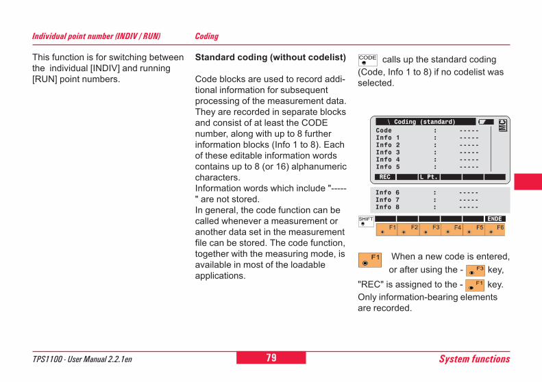
79TPS1100 - User Manual 2.2.1en System functions
6
10
12
21
26
This function is for switching betweenthe individual [INDIV] and running[RUN] point numbers.
Individual point number (INDIV / RUN) Coding
Standard coding (without codelist)
Code blocks are used to record addi-tional information for subsequentprocessing of the measurement data.They are recorded in separate blocksand consist of at least the CODEnumber, along with up to 8 furtherinformation blocks (Info 1 to 8). Eachof these editable information wordscontains up to 8 (or 16) alphanumericcharacters.Information words which include "-----" are not stored.In general, the code function can becalled whenever a measurement oranother data set in the measurementfile can be stored. The code function,together with the measuring mode, isavailable in most of the loadableapplications.
calls up the standard coding(Code, Info 1 to 8) if no codelist wasselected.
When a new code is entered,or after using the - key,
"REC" is assigned to the - key.Only information-bearing elementsare recorded.
\ Coding (standard)Code : -----Info 1 : -----Info 2 : -----Info 3 : -----Info 4 : -----Info 5 : -----
REC L Pt.
MC
ENDE
Info 6 : -----Info 7 : -----Info 8 : -----
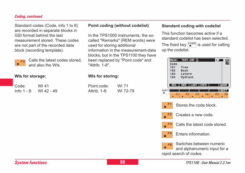
80System functions TPS1100 - User Manual 2.2.1en
Standard coding with codelist
This function becomes active if astandard codelist has been selected.The fixed key is used for callingup the codelist.
Stores the code block.
Creates a new code.
Calls the latest code stored.
Enters information.
Switches between numericand alphanumeric input for a
rapid search of codes.
MEAS\ TEST.CRF ⟨⟩⟨⟩⟨⟩⟨⟩⟨⟩Code101 Tree102 Bush103 Latern104 Hydrant
REC NEW LAST INFO αααααNUM
MC
QUIT
Coding, continued
Point coding (without codelist)
In the TPS1000 instruments, the so-called "Remarks" (REM words) wereused for storing additionalinformation in the measurement-datablocks, but in the TPS1100 they havebeen replaced by "Point code" and"Attrib. 1-8".
WIs for storing:
Point code: WI 71Attrib. 1-8: WI 72-79
Standard codes (Code, info 1 to 8)are recorded in separate blocks inGSI format behind the lastmeasurement stored. These codesare not part of the recorded datablock (recording template).
Calls the latest codes stored,and also the WIs.
WIs for storage:
Code: WI 41Info 1 - 8: WI 42 - 49
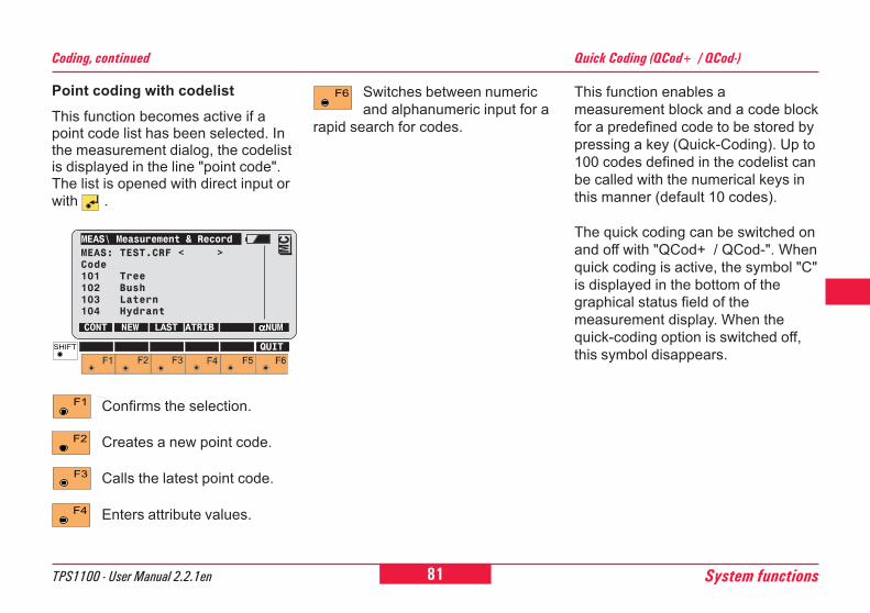
81TPS1100 - User Manual 2.2.1en System functions
6
10
12
21
26
Coding, continued
Point coding with codelistThis function becomes active if apoint code list has been selected. Inthe measurement dialog, the codelistis displayed in the line "point code".The list is opened with direct input orwith .
Confirms the selection.
Creates a new point code.
Calls the latest point code.
Enters attribute values.
MEAS\ Measurement & RecordMEAS: TEST.CRF < >Code101 Tree102 Bush103 Latern104 Hydrant
CONT NEW LAST ATRIB αααααNUM
MC
QUIT
This function enables ameasurement block and a code blockfor a predefined code to be stored bypressing a key (Quick-Coding). Up to100 codes defined in the codelist canbe called with the numerical keys inthis manner (default 10 codes).
The quick coding can be switched onand off with "QCod+ / QCod-". Whenquick coding is active, the symbol "C"is displayed in the bottom of thegraphical status field of themeasurement display. When thequick-coding option is switched off,this symbol disappears.
Quick Coding (QCod+ / QCod-)
Switches between numericand alphanumeric input for a
rapid search for codes.
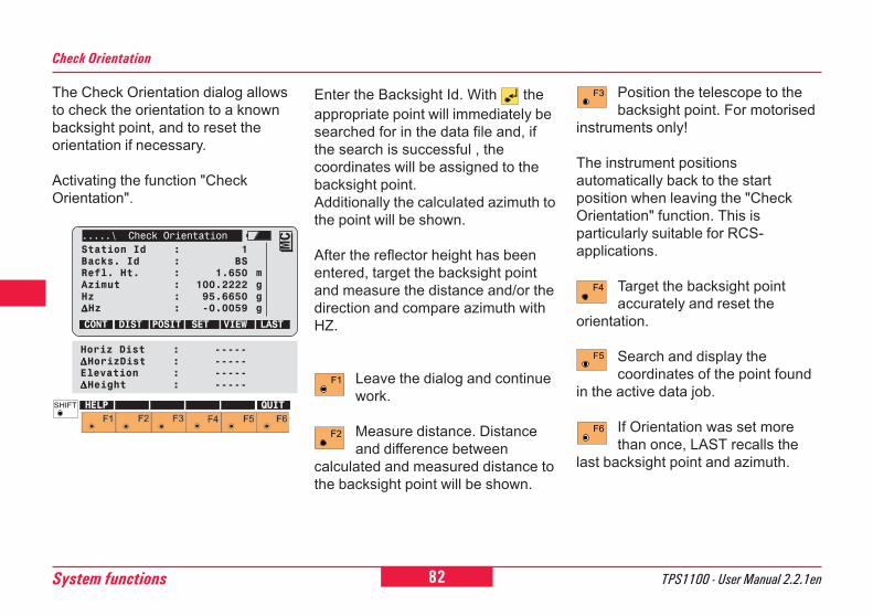
82System functions TPS1100 - User Manual 2.2.1en
The Check Orientation dialog allowsto check the orientation to a knownbacksight point, and to reset theorientation if necessary.
Activating the function "CheckOrientation".
Check Orientation
.....\ Check OrientationStation Id : 1Backs. Id : BSRefl. Ht. : 1.650 mAzimut : 100.2222 gHz : 95.6650 g∆∆∆∆∆Hz : -0.0059 g
CONT DIST POSIT SET VIEW LAST
MC
HELP QUIT
Horiz Dist : -----∆∆∆∆∆HorizDist : -----Elevation : -----∆∆∆∆∆Height : -----
Enter the Backsight Id. With theappropriate point will immediately besearched for in the data file and, ifthe search is successful , thecoordinates will be assigned to thebacksight point.Additionally the calculated azimuth tothe point will be shown.
After the reflector height has beenentered, target the backsight pointand measure the distance and/or thedirection and compare azimuth withHZ.
Leave the dialog and continuework.
Measure distance. Distanceand difference between
calculated and measured distance tothe backsight point will be shown.
Position the telescope to thebacksight point. For motorised
instruments only!
The instrument positionsautomatically back to the startposition when leaving the "CheckOrientation" function. This isparticularly suitable for RCS-applications.
Target the backsight pointaccurately and reset the
orientation.
Search and display thecoordinates of the point found
in the active data job.
If Orientation was set morethan once, LAST recalls the
last backsight point and azimuth.
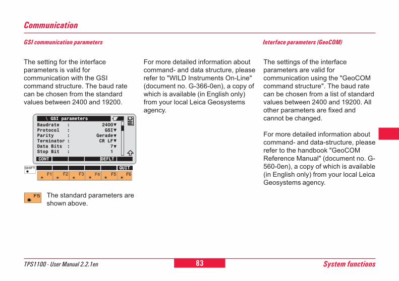
83TPS1100 - User Manual 2.2.1en System functions
6
10
12
21
26
GSI communication parameters
The standard parameters areshown above.
For more detailed information aboutcommand- and data structure, pleaserefer to "WILD Instruments On-Line"(document no. G-366-0en), a copy ofwhich is available (in English only)from your local Leica Geosystemsagency.
The setting for the interfaceparameters is valid forcommunication with the GSIcommand structure. The baud ratecan be chosen from the standardvalues between 2400 and 19200.
The settings of the interfaceparameters are valid forcommunication using the "GeoCOMcommand structure". The baud ratecan be chosen from a list of standardvalues between 2400 and 19200. Allother parameters are fixed andcannot be changed.
For more detailed information aboutcommand- and data-structure, pleaserefer to the handbook "GeoCOMReference Manual" (document no. G-560-0en), a copy of which is available(in English only) from your local LeicaGeosystems agency.
Interface parameters (GeoCOM)
Communication
\ GSI parametersBaudrate : 2400Protocol : GSIParity : GeradeTerminator : CR LFData Bits : 7Stop Bit : 1
CONT DEFLT
MC
QUIT
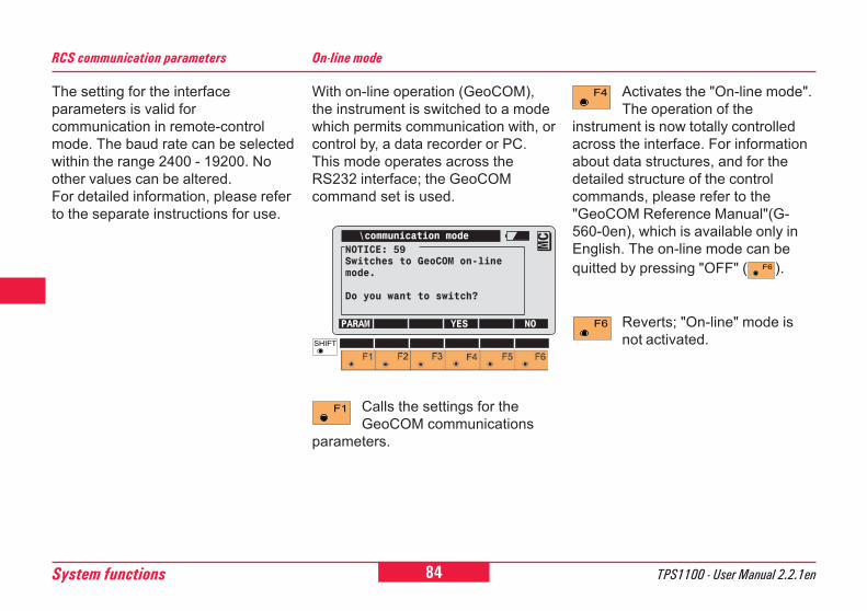
84System functions TPS1100 - User Manual 2.2.1en
6
0
2
21
26
RCS communication parameters
The setting for the interfaceparameters is valid forcommunication in remote-controlmode. The baud rate can be selectedwithin the range 2400 - 19200. Noother values can be altered.For detailed information, please referto the separate instructions for use.
With on-line operation (GeoCOM),the instrument is switched to a modewhich permits communication with, orcontrol by, a data recorder or PC.This mode operates across theRS232 interface; the GeoCOMcommand set is used.
On-line mode
Calls the settings for theGeoCOM communications
parameters.
Activates the "On-line mode".The operation of the
instrument is now totally controlledacross the interface. For informationabout data structures, and for thedetailed structure of the controlcommands, please refer to the"GeoCOM Reference Manual"(G-560-0en), which is available only inEnglish. The on-line mode can bequitted by pressing "OFF" ( ).
Reverts; "On-line" mode isnot activated.
\communication modeNOTICE: 59Switches to GeoCOM on-linemode.
Do you want to switch?
PARAM YES NO
MC
85TPS1100 - User Manual 2.2.1en System functions
6
10
12
21
26
TCA and TCRA instruments aremotorized and equipped withAutomatic Target Recognition (ATR)coaxially in the telescope. The EGLguide light, mounted on thetelescope, is optional.These instruments permit automaticangle and distance measurements tonormal prisms and reduce the tediumof precise visual sighting to prisms.The prism is sighted with the opticalsight only. Initiating a distancemeasurement will turn the instrumentwith the help of the motors to sightthe prism-centre automatically.The angles V and Hz are measuredto the centre of the prism at thecompletion of the distancemeasurement.
Automatic Target Recognition
As with all other instrumenterrors, the collimation error
of the automatic target recognition(ATR) must be redeterminedperiodically (Refer to chapter"Checking and Adjusting").
Reflections or foreign lights(eg. from car headlights) can
affect the ATR-measurement.
Functionality
The built-in Automatic TargetRecognition ATR1 transmits a laserbeam. The reflected light is receivedby the built-in camera (CCD). Theposition of the received light spot withrespect to the centre of the CCD iscomputed and the offsets are used tocorrect the horizontal and verticalangles. The offsets are also used tocontrol the motors which turn theinstrument so that the crosshairs arecentred on the prism.
In order to minimize the times formeasuring, the crosshair is notmoved to the exact centre of theprism. The offset can be up to 5mm.Then the Automatic TargetRecognition ATR1 measures theoffsets between the crosshair andprism centre and corrects the Hz andV angles accordingly.
Therefore the Hz and V angles aremeasured to the prism-centre,regardless of the crosshair pointingprecisely to the centre of the prism.
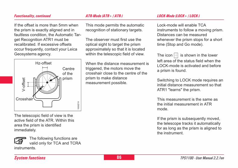
86System functions TPS1100 - User Manual 2.2.1en
6
0
2
21
26
If the offset is more than 5mm whenthe prism is exactly aligned and infaultless condition, the Automatic Tar-get Recognition ATR1 must berecalibrated. If excessive offsetsoccur frequently, contact your LeicaGeosystems agency.
Hz-offset
1000
Z19
Centreof theprism
V-of
fset
Functionality, continued
Crosshair
The telescopic field of view is theactive field of the ATR. Within thisarea the prism is identifiedimmediately.
The following functions arevalid only for TCA and TCRA
instruments.
This mode permits the automaticrecognition of stationary targets.
The observer must first use theoptical sight to target the prismapproximately so that it is locatedwithin the telescopic field of view.
When the distance measurement istriggered, the motors move thecrosshair close to the centre of theprism to make distancemeasurement possible.
ATR-Mode (ATR+ / ATR-) LOCK-Mode (LOCK+ / LOCK-)
Lock-mode will enable TCAinstruments to follow a moving prism.Distances can be measuredwhenever the prism stops for a shorttime (Stop and Go mode).
The icon is shown in the lowerleft area of the status field when theLOCK-mode is activated and beforea prism is found.
Switching to LOCK mode requires aninitial distance measurement so thatATR1 "learns" the prism.
This measurement is the same asthe initial measurement in ATRmode.
If the prism is subsequently moved,the telescope tracks it automaticallyfor as long as the prism is aligned tothe instrument.
87TPS1100 - User Manual 2.2.1en System functions
6
10
12
21
26
LOCK-Mode (LOCK+ / LOCK-), continued
The displayed angles refer to thecrosshair direction during search.Once the prism is static, a distancemeasurement can be activated using"DIST" or "ALL". In this case theangles are measured on the centre ofthe prism after the distancemeasurement.
After a distance measurement, thesecorrected angles (for the centre ofthe prism) are displayed or recorded.
The icon is shown in the lowerleft area of the status field if theLOCK mode is active and if thetelescope tracks the prism
Any interruption to the tracking of theprism is indicated for about twoseconds graphically in the lower leftstatus field by the symbol andalso by a continuous acoustic signal(beep).
L.UNT-Mode (L.INT+ / L.GO)
The LOCK mode is interrupted(LOCK Interrupt), e.g. to measureinbetween to faraway targets withoutprism (eg. church spires). After thedistance has been measured, theATR immediately returns to its origi-nal condition.
This function should be used formeasuring to a second prism (Chan-ging the prism).
The icon is shown in the lowerleft area of the status field, once theL.INT-mode is activated. Measuredangles refer to the direction of thecrosshair.
At the completion of the distancemeasurement or after pressing L.GO,the LOCK mode is reactivated andthe corresponding icon is shown inthe lower left area of the status field.
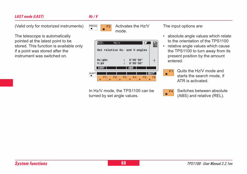
88System functions TPS1100 - User Manual 2.2.1en
6
0
2
21
26
(Valid only for motorized instruments)
The telescope is automaticallypointed at the latest point to bestored. This function is available onlyif a point was stored after theinstrument was switched on.
LAST mode (LAST) Hz / V
Activates the Hz/Vmode.
In Hz/V mode, the TPS1100 can beturned by set angle values.
The input options are:
� absolute angle values which relateto the orientation of the TPS1100
� relative angle values which causethe TPS1100 to turn away from itspresent position by the amountentered.
Quits the Hz/V mode andstarts the search mode, ifATR is activated.
Switches between absolute(ABS) and relative (REL).
RCS\ Hz/v
Set relative Hz- and V-angles
Hz/∆∆∆∆∆Hz : 0°00'00"V/∆∆∆∆∆V : 0°00'00"
CONT ABS
MC
QUIT
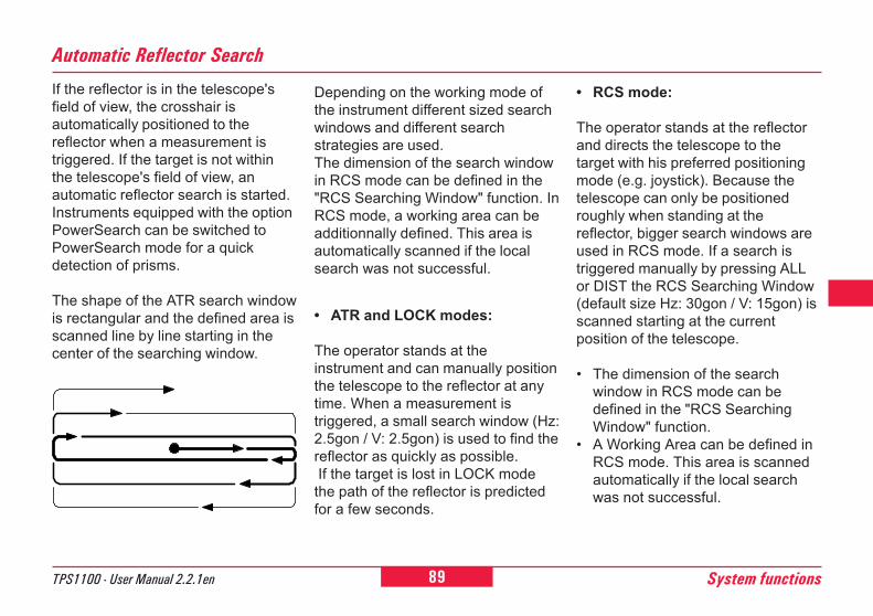
89TPS1100 - User Manual 2.2.1en System functions
6
10
12
21
26
Automatic Reflector Search
If the reflector is in the telescope'sfield of view, the crosshair isautomatically positioned to thereflector when a measurement istriggered. If the target is not withinthe telescope's field of view, anautomatic reflector search is started.Instruments equipped with the optionPowerSearch can be switched toPowerSearch mode for a quickdetection of prisms.
The shape of the ATR search windowis rectangular and the defined area isscanned line by line starting in thecenter of the searching window.
Depending on the working mode ofthe instrument different sized searchwindows and different searchstrategies are used.The dimension of the search windowin RCS mode can be defined in the"RCS Searching Window" function. InRCS mode, a working area can beadditionnally defined. This area isautomatically scanned if the localsearch was not successful.
� ATR and LOCK modes:
The operator stands at theinstrument and can manually positionthe telescope to the reflector at anytime. When a measurement istriggered, a small search window (Hz:2.5gon / V: 2.5gon) is used to find thereflector as quickly as possible. If the target is lost in LOCK modethe path of the reflector is predictedfor a few seconds.
� RCS mode:
The operator stands at the reflectorand directs the telescope to thetarget with his preferred positioningmode (e.g. joystick). Because thetelescope can only be positionedroughly when standing at thereflector, bigger search windows areused in RCS mode. If a search istriggered manually by pressing ALLor DIST the RCS Searching Window(default size Hz: 30gon / V: 15gon) isscanned starting at the currentposition of the telescope.
� The dimension of the searchwindow in RCS mode can bedefined in the "RCS SearchingWindow" function.
� A Working Area can be defined inRCS mode. This area is scannedautomatically if the local searchwas not successful.
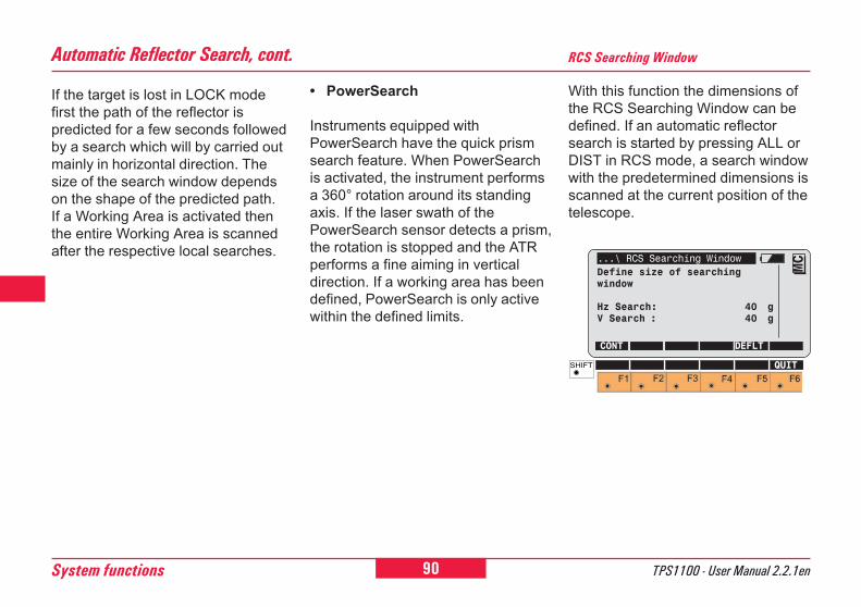
90System functions TPS1100 - User Manual 2.2.1en
6
0
2
21
26
RCS Searching Window
With this function the dimensions ofthe RCS Searching Window can bedefined. If an automatic reflectorsearch is started by pressing ALL orDIST in RCS mode, a search windowwith the predetermined dimensions isscanned at the current position of thetelescope.
...\ RCS Searching WindowDefine size of searchingwindow
Hz Search: 40 gV Search : 40 g
CONT DEFLT
MC
QUIT
Automatic Reflector Search, cont.
If the target is lost in LOCK modefirst the path of the reflector ispredicted for a few seconds followedby a search which will by carried outmainly in horizontal direction. Thesize of the search window dependson the shape of the predicted path.If a Working Area is activated thenthe entire Working Area is scannedafter the respective local searches.
� PowerSearch
Instruments equipped withPowerSearch have the quick prismsearch feature. When PowerSearchis activated, the instrument performsa 360° rotation around its standingaxis. If the laser swath of thePowerSearch sensor detects a prism,the rotation is stopped and the ATRperforms a fine aiming in verticaldirection. If a working area has beendefined, PowerSearch is only activewithin the defined limits.
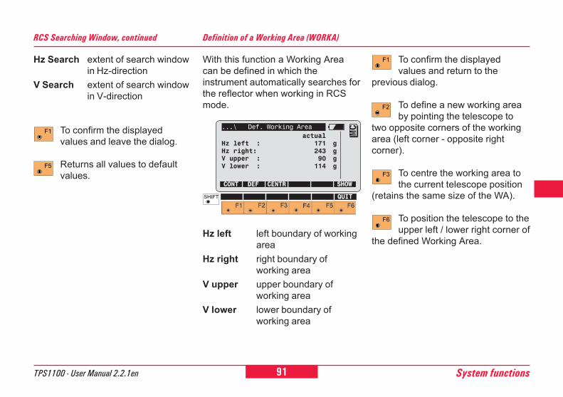
91TPS1100 - User Manual 2.2.1en System functions
6
10
12
21
26
Hz Search extent of search windowin Hz-direction
V Search extent of search windowin V-direction
To confirm the displayedvalues and leave the dialog.
Returns all values to defaultvalues.
Definition of a Working Area (WORKA)
With this function a Working Areacan be defined in which theinstrument automatically searches forthe reflector when working in RCSmode.
...\ Def. Working Areaactual
Hz left : 171 gHz right: 243 gV upper : 90 gV lower : 114 g
CONT DEF CENTR SHOW
MC
QUIT
Hz left left boundary of workingarea
Hz right right boundary ofworking area
V upper upper boundary ofworking area
V lower lower boundary ofworking area
To confirm the displayedvalues and return to the
previous dialog.
To define a new working areaby pointing the telescope to
two opposite corners of the workingarea (left corner - opposite rightcorner).
To centre the working area tothe current telescope position
(retains the same size of the WA).
To position the telescope to theupper left / lower right corner of
the defined Working Area.
RCS Searching Window, continued
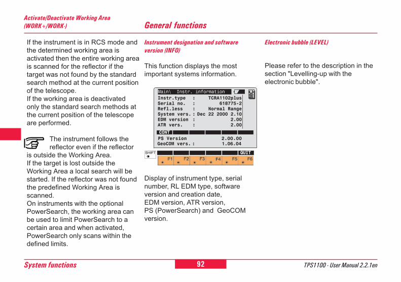
92System functions TPS1100 - User Manual 2.2.1en
6
0
2
21
26
General functions
Instrument designation and softwareversion (INFO)
This function displays the mostimportant systems information.
Please refer to the description in thesection "Levelling-up with theelectronic bubble".
Electronic bubble (LEVEL)
Activate/Deactivate Working Area(WORK+/WORK-)
If the instrument is in RCS mode andthe determined working area isactivated then the entire working areais scanned for the reflector if thetarget was not found by the standardsearch method at the current positionof the telescope.If the working area is deactivatedonly the standard search methods atthe current position of the telescopeare performed.
The instrument follows thereflector even if the reflector
is outside the Working Area.If the target is lost outside theWorking Area a local search will bestarted. If the reflector was not foundthe predefined Working Area isscanned.On instruments with the optionalPowerSearch, the working area canbe used to limit PowerSearch to acertain area and when activated,PowerSearch only scans within thedefined limits.
Display of instrument type, serialnumber, RL EDM type, softwareversion and creation date,EDM version, ATR version,PS (PowerSearch) and GeoCOMversion.
Main\ Instr. informationInstr.type : TCRA1102plusSerial no. : 618775-2Refl.less : Normal RangeSystem vers. : Dec 22 2000 2.10EDM version : 2.00ATR vers. : 2.00
CONT
MC
QUIT
GeoCOM vers. : 1.06.04PS Version 2.00.00
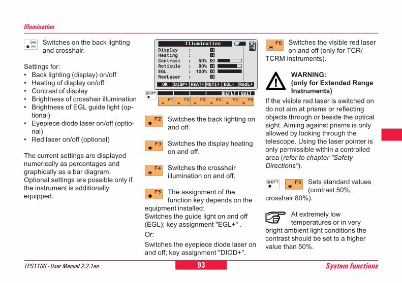
93TPS1100 - User Manual 2.2.1en System functions
6
10
12
21
26
Illumination
Switches on the back lightingand crosshair.
Settings for:� Back lighting (display) on/off� Heating of display on/off� Contrast of display� Brightness of crosshair illumination� Brightness of EGL guide light (op-
tional)� Eyepiece diode laser on/off (optio-
nal)� Red laser on/off (optional)
The current settings are displayednumerically as percentages andgraphically as a bar diagram.Optional settings are possible only ifthe instrument is additionallyequipped.
Switches the back lighting onand off.
Switches the display heatingon and off.
Switches the crosshairillumination on and off.
The assignment of thefunction key depends on the
equipment installed:Switches the guide light on and off(EGL); key assignment "EGL+" .Or:Switches the eyepiece diode laser onand off; key assignment "DIOD+".
IlluminationDisplay : ⌧⌧⌧⌧⌧Heating : ⌧⌧⌧⌧⌧Contrast : 50% ⌧⌧⌧⌧⌧Reticule : 80% ⌧⌧⌧⌧⌧EGL : 100% ⌧⌧⌧⌧⌧RedLaser : ⌧⌧⌧⌧⌧
OK DISP+ HEAT+ RETI+ EGL+ RedL+
MC
DEFLT QUIT
Switches the visible red laseron and off (only for TCR/
TCRM instruments).
WARNING:(only for Extended RangeInstruments)
If the visible red laser is switched ondo not aim at prisms or reflectingobjects through or beside the opticalsight. Aiming against prisms is onlyallowed by looking through thetelescope. Using the laser pointer isonly permissible within a controlledarea (refer to chapter "SafetyDirections").
Sets standard values(contrast 50%,
crosshair 80%).
At extremely lowtemperatures or in very
bright ambient light conditions thecontrast should be set to a highervalue than 50%.
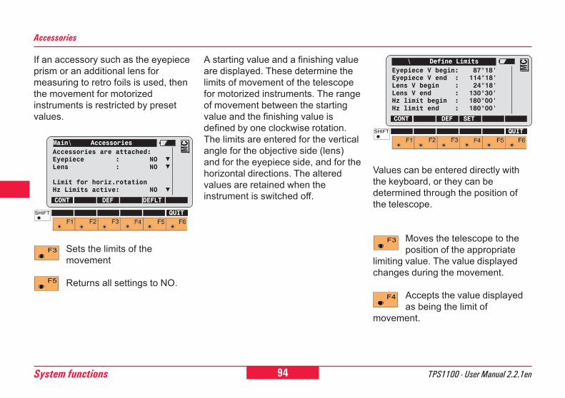
94System functions TPS1100 - User Manual 2.2.1en
6
0
2
21
26 Values can be entered directly withthe keyboard, or they can bedetermined through the position ofthe telescope.
Moves the telescope to theposition of the appropriate
limiting value. The value displayedchanges during the movement.
Accepts the value displayedas being the limit of
movement.
\ Define LimitsEyepiece V begin: 87°18'Eyepiece V end : 114°18'Lens V begin : 24°18'Lens V end : 130°30'Hz limit begin : 180°00'Hz limit end : 180°00'
CONT DEF SET
MC
QUIT
If an accessory such as the eyepieceprism or an additional lens formeasuring to retro foils is used, thenthe movement for motorizedinstruments is restricted by presetvalues.
Sets the limits of themovement
Returns all settings to NO.
Accessories
A starting value and a finishing valueare displayed. These determine thelimits of movement of the telescopefor motorized instruments. The rangeof movement between the startingvalue and the finishing value isdefined by one clockwise rotation.The limits are entered for the verticalangle for the objective side (lens)and for the eyepiece side, and for thehorizontal directions. The alteredvalues are retained when theinstrument is switched off.
Main\ AccessoriesAccessories are attached:Eyepiece : NOLens : NO
Limit for horiz.rotationHz Limits active: NO
CONT DEF DEFLT
MC
QUIT
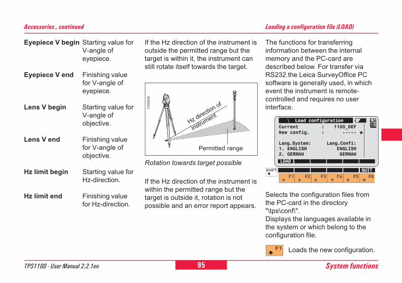
95TPS1100 - User Manual 2.2.1en System functions
6
10
12
21
26
Accessories , continued
If the Hz direction of the instrument isoutside the permitted range but thetarget is within it, the instrument canstill rotate itself towards the target.
If the Hz direction of the instrument iswithin the permitted range but thetarget is outside it, rotation is notpossible and an error report appears.
Hz direction of
instrument
Permitted range11
00Z4
5
Rotation towards target possible
Eyepiece V begin Starting value forV-angle ofeyepiece.
Eyepiece V end Finishing valuefor V-angle ofeyepiece.
Lens V begin Starting value forV-angle ofobjective.
Lens V end Finishing valuefor V-angle ofobjective.
Hz limit begin Starting value forHz-direction.
Hz limit end Finishing valuefor Hz-direction.
The functions for transferringinformation between the internalmemory and the PC-card aredescribed below. For transfer viaRS232 the Leica SurveyOffice PCsoftware is generally used, in whichevent the instrument is remote-controlled and requires no userinterface.
Loading a configuration file (LOAD)
\ Load configurationCurrent : 1100_DEFNew config. : -----
Lang.System: Lang.Confi:1. ENGLISH ENGLISH2. GERMAN GERMAN
LOAD
MC
QUIT
Selects the configuration files fromthe PC-card in the directory"\tps\conf\".Displays the languages available inthe system or which belong to theconfiguration file.
Loads the new configuration.
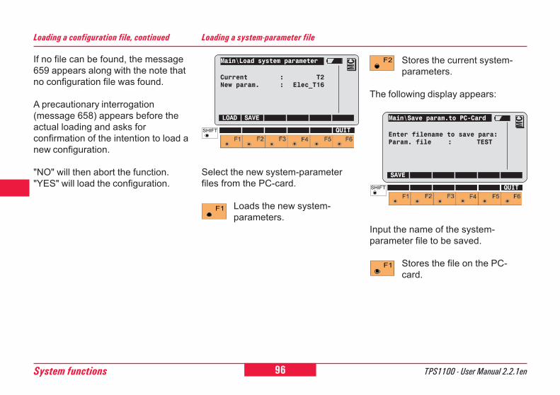
96System functions TPS1100 - User Manual 2.2.1en
6
0
2
21
26
Stores the current system-parameters.
The following display appears:
Main\Save param.to PC-Card
Enter filename to save para:Param. file : TEST
SAVE
MC
QUIT
Input the name of the system-parameter file to be saved.
Stores the file on the PC-card.
Loading a system-parameter file
Main\Load system parameter
Current : T2New param. : Elec_T16
LOAD SAVE
MC
QUIT
Select the new system-parameterfiles from the PC-card.
Loads the new system-parameters.
Loading a configuration file, continued
If no file can be found, the message659 appears along with the note thatno configuration file was found.
A precautionary interrogation(message 658) appears before theactual loading and asks forconfirmation of the intention to load anew configuration.
"NO" will then abort the function."YES" will load the configuration.
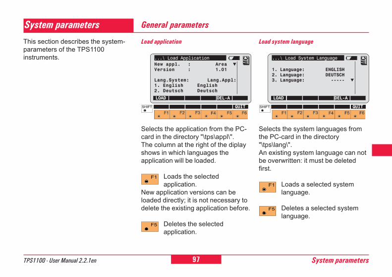
97TPS1100 - User Manual 2.2.1en System parameters
6
10
12
21
26
45
System parametersThis section describes the system-parameters of the TPS1100instruments.
General parameters
Load application
Selects the application from the PC-card in the directory "\tps\appl\".The column at the right of the diplayshows in which languages theapplication will be loaded.
Loads the selectedapplication.
New application versions can beloaded directly; it is not necessary todelete the existing application before.
Deletes the selectedapplication.
...\ Load ApplicationNew appl. : AreaVersion : 1.01
Lang.System: Lang.Appl:1. English English2. Deutsch Deutsch
LOAD DEL-A
MC
QUIT
Load system language
Selects the system languages fromthe PC-card in the directory"\tps\lang\".An existing system language can notbe overwritten: it must be deletedfirst.
Loads a selected systemlanguage.
Deletes a selected systemlanguage.
...\ Load System Language
1. Language: ENGLISH2. Language: DEUTSCH3. Language: -----
LOAD DEL-A
MC
QUIT
98System parameters TPS1100 - User Manual 2.2.1en
6
0
2
21
26
45
Date form.
Selects the date format.Choice of layout:Day/Month/YearMonth/Day/YearYear/Month/Day
Date
Sets the date.Choice of layout: 09-11-98 or11.09.98.
Time
Sets the time.
Alpha mode
The alphanumeric input can be eitherthrough the function keys or throughthe numeric keys. If numeric keys areused, there is a choice between"Numeric keys" and "Numeric exten-ded". In "Numeric extended" mode,more characters are available.
Key beep
Sets the volume of the beep emittedwhen the keys are pressed. Thebeep is always active for messages.There is a choice between beep off(None), soft beep (Low) and loudbeep (Loud).
Time form.
Sets the time format.Choice between 24h clockand 12h clock with am/pm
General parameters, continued
99TPS1100 - User Manual 2.2.1en System parameters
6
10
12
21
26
45
Configuration parameters
Autoexec.
Selects the application, which willthen be started automaticallyimmediately after switching on.The list includes the followingpermanently-available options: "Mainmenu", "Measurement & Recording"and "Enter Station Data". Also, all ofthe applications programs loaded arelisted.The function or application selectedis automatically started whenever theinstrument is switched on.
Dist. Unit
Units of distance measurement:Metre Metres (m)Int.Ft International feet,
storage in US feet [fi]Int.Ft/Inch Int. feet, inches and 1/8
inches(0' 00 0/8fi),storage in US feet [fi]
US Ft US feet [ft]US Ft/Inch US feet, inches and 1/8
inches(0' 00 0/8fi) [ft]
Language
Selects the system language (amaximum of three languages can bestored). English is always availableand cannot be deleted.
Dist. Dec.
Decimal places for distance:Metre 0,1,2,3Int.Ft 0,1,2,3Int.Ft/Inch 0US Ft 0,1,2,3US Ft/Inch 0
Angle Unit
Units of angle measurement:400gon360° ' "360° dec6400 mil
Angle Dec.
Decimal places for angle:
TCx1101/1102:� 400 gon, 360°'", 360°dec.
=> 2, 3, 4� 6400 mil => 1, 2, 3
TCx1103/1105:� 400 gon, 360° dec. => 2, 3, 4
(in steps of five units)� 360°'" => 2, 3, 4� 6400 mil => 1, 2, 3
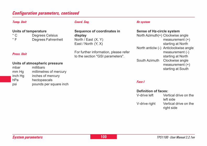
100System parameters TPS1100 - User Manual 2.2.1en
6
0
2
21
26
45
Configuration parameters, continued
Temp. Unit
Units of temperature° C Degrees Celsius° F Degrees Fahrenheit
Press. Unit
Units of atmospheric pressurembar millibarsmm Hg millimetres of mercuryinch Hg inches of mercuryhPa hectopascalspsi pounds per square inch
Face I
Definition of faces:V-drive left Vertical drive on the
left sideV-drive right Vertical drive on the
right side
Coord. Seq.
Sequence of coordinates indisplayNorth / East (X, Y)East / North (Y, X)
For further information, please referto the section "GSI parameters".
Hz system
Sense of Hz-circle systemNorth Azimuth(+) Clockwise angle
measurement (+)starting at North
North anticlw (-) Anticlockwise anglemeasurement (-)starting at North
South Azimuth Clockwise anglemeasurement (+)starting at South
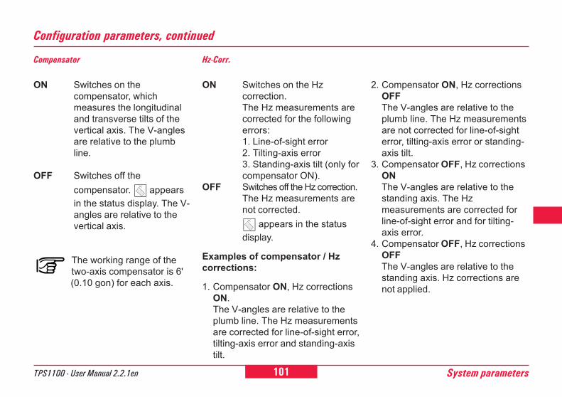
101TPS1100 - User Manual 2.2.1en System parameters
6
10
12
21
26
45
Configuration parameters, continued
Compensator
ON Switches on thecompensator, whichmeasures the longitudinaland transverse tilts of thevertical axis. The V-anglesare relative to the plumbline.
OFF Switches off thecompensator. appearsin the status display. The V-angles are relative to thevertical axis.
The working range of thetwo-axis compensator is 6'(0.10 gon) for each axis.
Hz-Corr.
ON Switches on the Hzcorrection.The Hz measurements arecorrected for the followingerrors:1. Line-of-sight error2. Tilting-axis error3. Standing-axis tilt (only forcompensator ON).
OFF Switches off the Hz correction.The Hz measurements arenot corrected.
appears in the statusdisplay.
Examples of compensator / Hzcorrections:
1. Compensator ON, Hz correctionsON.The V-angles are relative to theplumb line. The Hz measurementsare corrected for line-of-sight error,tilting-axis error and standing-axistilt.
2. Compensator ON, Hz correctionsOFFThe V-angles are relative to theplumb line. The Hz measurementsare not corrected for line-of-sighterror, tilting-axis error or standing-axis tilt.
3. Compensator OFF, Hz correctionsONThe V-angles are relative to thestanding axis. The Hzmeasurements are corrected forline-of-sight error and for tilting-axis error.
4. Compensator OFF, Hz correctionsOFFThe V-angles are relative to thestanding axis. Hz corrections arenot applied.
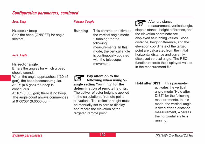
102System parameters TPS1100 - User Manual 2.2.1en
6
0
2
21
26
45
After a distancemeasurement, vertical angle,
slope distance, height difference, andthe elevation coordinate aredisplayed as running values. Slopedistance, height difference, and theelevation coordinate of the targetpoint are calculated from the initialhorizontal distance and currentlydisplayed vertical angle. The REC-function records the displayed valuesin the measurement file.
Hold after DIST This parameteractivates the verticalangle mode "Hold afterDIST" for the followingmeasurements. In thismode, the vertical angleis fixed after a distancemeasurement, whereasthe horizontal angle isrunning.
Configuration parameters, continued
Sect. Beep
Hz sector beepSets the beep (ON/OFF) for anglesectors.
Sect. Angle
Hz sector angleEnters the angles for which a beepshould sound.When the angle approaches 4°30' (5gon), the beep becomes regular.At 27' (0.5 gon) the beep iscontinuous.At 16" (0.005 gon) there is no beep.The angle count always commencesat 0°00'00" (0.0000 gon).
Release V-angle
Running This parameter activatesthe vertical angle mode"Running" for thefollowingmeasurements. In thismode, the vertical angleis continuously updatedwith the telescopemovement.
Pay attention to thefollowing when using V-
angle setting "running" for thedetermination of remote heights:The active reflector height is appliedin the calculation of remote pointelevations. The reflector height mustbe manually set to zero to displayand record the elevation of thetargeted remote point.
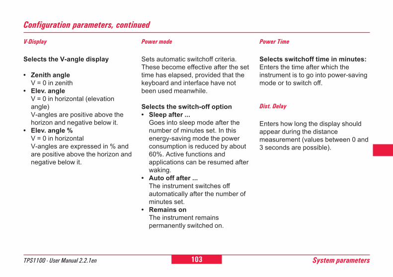
103TPS1100 - User Manual 2.2.1en System parameters
6
10
12
21
26
45
V-Display
Selects the V-angle display
� Zenith angleV = 0 in zenith
� Elev. angleV = 0 in horizontal (elevationangle)V-angles are positive above thehorizon and negative below it.
� Elev. angle %V = 0 in horizontalV-angles are expressed in % andare positive above the horizon andnegative below it.
Power mode
Sets automatic switchoff criteria.These become effective after the settime has elapsed, provided that thekeyboard and interface have notbeen used meanwhile.
Selects the switch-off option� Sleep after ...
Goes into sleep mode after thenumber of minutes set. In thisenergy-saving mode the powerconsumption is reduced by about60%. Active functions andapplications can be resumed afterwaking.
� Auto off after ...The instrument switches offautomatically after the number ofminutes set.
� Remains onThe instrument remainspermanently switched on.
Configuration parameters, continued
Power Time
Selects switchoff time in minutes:Enters the time after which theinstrument is to go into power-savingmode or to switch off.
Dist. Delay
Enters how long the display shouldappear during the distancemeasurement (values between 0 and3 seconds are possible).
104System parameters TPS1100 - User Manual 2.2.1en
6
0
2
21
26
45
PPM entry
Choice between display mask forreduced distance corrections (ppmatmospheric) for standardapplications and display mask for ex-tended distance corrections (ppmatmospheric + geometrical).
PPM AtmosphericDirect input of the ppm value (ppmtotal) or input of temperature andpressure for automatic calculation ofppm atmospheric.
Info / Atrib
Display of the last attribute entry
Default valueThe default value defined in thecodelist is displayed and can beoverwritten.
Last user valueInstead of default values orchoicelists, the last entered values(Info's/Attributes) are displayed foreach code.Note predefined default values forInfos and attributes are overwrittenby the last entered values and cannot be anymore recovered!
PPM atmospheric + geometricalA distinction is made betweenatmospheric corrections(temperature, relative air humidityand air pressure) and geometricalcorrections (projection distortion,scale factor and height above thereference datum), the sum of whichis used as the final distancecorrection.
Configuration parameters, continued
105TPS1100 - User Manual 2.2.1en System parameters
6
10
12
21
26
45
Measurement parameters
Pt. Id. mode
In the measurement dialog and in theprograms, the Point Id is defined as arunning point number withcorresponding increment.
Mode "Change to Indiv":The user can enter individual PointIds manually at any time. Afterrecording, the active running Point Idwill be displayed again.
Mode "Remain running":The manual entry of a new Point Iddefines a new running Point Id.
Offs. Mode
Determines whether the values fortarget eccentricity are to be retainedafter storage or are to be set to zero(choice between "Permanent" and"No reset after REC").
Auto Dist
ON Activates automaticdistance measurementafter choice of EDM-pro-gram with function key.
OFF Deactivates automaticdistance measurementafter choice of EDM-pro-gram with function key.
Configuration parameters, cont.
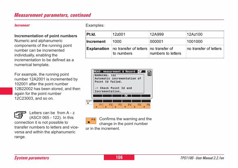
106System parameters TPS1100 - User Manual 2.2.1en
6
0
2
21
26
45
Increment
Incrementation of point numbersNumeric and alphanumericcomponents of the running pointnumber can be incrementedindividually, enabling theincrementation to be defined as anumerical template.
For example, the running pointnumber 12A2001 is incremented by102001 after the point number12B22002 has been stored, and thenagain for the point number12C23003, and so on.
Letters can be from A - z(ASCII 065 - 122). In this
connection it is not possible totransfer numbers to letters and vice-versa and within the alphanumericrange.
Measurement parameters, continued
Examples:
Confirms the warning and thechange in the point number
or in the increment.
MEAS\ measurement & RecordWARNING: 152Automatic incrementation ofPoint Id failed.
-> Check Point Id andIncrementation.
OK
MC
Pt.Id. 12z001 12A999 12Az100
Increment 1000 000001 1001000
Explanation no transfer of lettersto numbers
no transfer ofnumbers to letters
no transfer of letters
107TPS1100 - User Manual 2.2.1en System parameters
6
10
12
21
26
45
Work settings
Meas Job
Displays the measuring jobs whichare available and selects theappropriate one.
Data Job
Displays the data jobs which areavailable and selects the appropriateone.
Codelist
Displays the code lists which areavailable and selects the appropriateone.
Quick-Code
Stores the code block before or afterthe measurement if the quick-codemethod is used. Choice between"REC before ALL" and "REC afterALL".
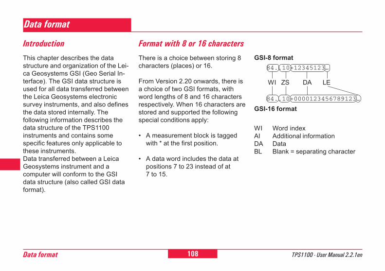
108Data format TPS1100 - User Manual 2.2.1en
6
0
2
21
26
45
84
Data format
This chapter describes the datastructure and organization of the Lei-ca Geosystems GSI (Geo Serial In-terface). The GSI data structure isused for all data transferred betweenthe Leica Geosystems electronicsurvey instruments, and also definesthe data stored internally. Thefollowing information describes thedata structure of the TPS1100instruments and contains somespecific features only applicable tothese instruments.Data transferred between a LeicaGeosystems instrument and acomputer will conform to the GSIdata structure (also called GSI dataformat).
Format with 8 or 16 characters
There is a choice between storing 8characters (places) or 16.
From Version 2.20 onwards, there isa choice of two GSI formats, withword lengths of 8 and 16 charactersrespectively. When 16 characters arestored and supported the followingspecial conditions apply:
� A measurement block is taggedwith * at the first position.
� A data word includes the data atpositions 7 to 23 instead of at7 to 15.
WI Word indexAI Additional informationDA DataBL Blank = separating character
Introduction
GSI-16 format
GSI-8 format84..10+12345123
84..10+0000123456789123
WI ZS DA LE
109TPS1100 - User Manual 2.2.1en Data format
6
10
12
21
26
45
84
Data transmitted by instruments overthe GSI interface is composed ofblocks. Each one of these datablocks is treated as a whole, andends with a terminator (CR, or CRLF). There are two types of datablock:
1 Measurement blocks2 Code blocks
Measurement blocks contain a pointnumber and measurementinformation. They are designedprimarily for triangulation, traverse,detail, and tacheometric surveys.Code blocks are designed primarilyfor recording identification codes,data-processing codes andinformation. However, they can alsobe used for recording measurementinformation such as instrument andtarget heights, and tie distances.
Block concept
Each data block has a blocknumber. The block numbers startwith 1 and are incremented by 1 eachtime that a new data block is stored.
Structure of a block
A data block consists of words, eachwith 16 (24) characters. Themaximum number of words in theTPS1100 is 12.
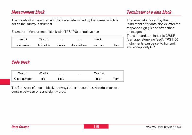
110Data format TPS1100 - User Manual 2.2.1en
6
0
2
21
26
45
84
The words of a measurement block are determined by the format which isset on the survey instrument.
Example: Measurement block with TPS1000 default values
Measurement block
Code block
The first word of a code block is always the code number. A code block cancontain between one and eight words.
Terminator of a data block
The terminator is sent by theinstrument after data blocks, after theresponse sign (?) and after othermessages.The standard terminator is CR/LF(carriage return/line feed). TPS1100instruments can be set to transmitand accept only CR.
Word 1 Word 2 ..... ..... Word n
Point number Hz direction V angle Slope distance ppm mm Term
Word 1 Word 2 ..... ..... Word n
Code number Info1 Info2 Info n Term
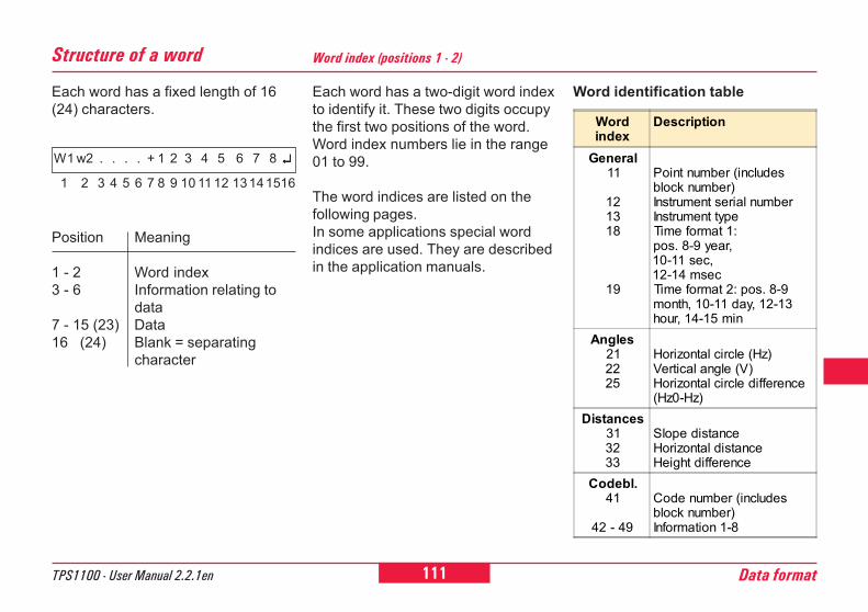
111TPS1100 - User Manual 2.2.1en Data format
6
10
12
21
26
45
84
Each word has a fixed length of 16(24) characters.
Structure of a word
Position Meaning
1 - 2 Word index3 - 6 Information relating to
data7 - 15 (23) Data16 (24) Blank = separating
character
W1 w2 . . . . + 1 2 3 4 5 6 7 8 ↵↵↵↵↵
1 2 3 4 5 6 7 8 9 10 11 12 13141516
Each word has a two-digit word indexto identify it. These two digits occupythe first two positions of the word.Word index numbers lie in the range01 to 99.
The word indices are listed on thefollowing pages.In some applications special wordindices are used. They are describedin the application manuals.
Word identification table
Word index (positions 1 - 2)
Wordindex
Description
General11
121318
19
Point number (includesblock number)Instrument serial numberInstrument typeTime format 1:pos. 8-9 year,10-11 sec,12-14 msecTime format 2: pos. 8-9month, 10-11 day, 12-13hour, 14-15 min
Angles212225
Horizontal circle (Hz)Vertical angle (V)Horizontal circle difference(Hz0-Hz)
Distances313233
Slope distanceHorizontal distanceHeight difference
Codebl.41
42 - 49
Code number (includesblock number)Information 1-8
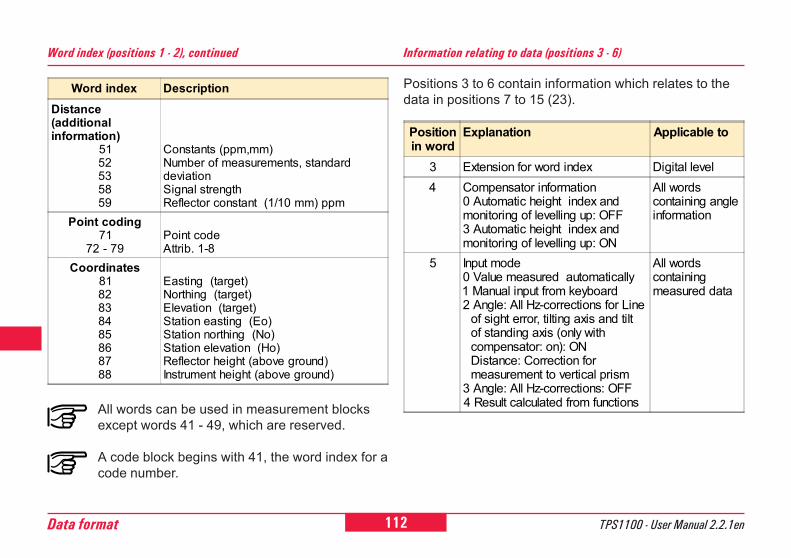
112Data format TPS1100 - User Manual 2.2.1en
6
0
2
21
26
45
84
Word index (positions 1 - 2), continued
All words can be used in measurement blocksexcept words 41 - 49, which are reserved.
A code block begins with 41, the word index for acode number.
Information relating to data (positions 3 - 6)
Positions 3 to 6 contain information which relates to thedata in positions 7 to 15 (23).
Positionin word
Explanation Applicable to
3 Extension for word index Digital level4 Compensator information
0 Automatic height index andmonitoring of levelling up: OFF3 Automatic height index andmonitoring of levelling up: ON
All wordscontaining angleinformation
5 Input mode0 Value measured automatically1 Manual input from keyboard2 Angle: All Hz-corrections for Line of sight error, tilting axis and tilt of standing axis (only with compensator: on): ON Distance: Correction for measurement to vertical prism3 Angle: All Hz-corrections: OFF4 Result calculated from functions
All wordscontainingmeasured data
Word index DescriptionDistance(additionalinformation)
5152535859
Constants (ppm,mm)Number of measurements, standarddeviationSignal strengthReflector constant (1/10 mm) ppm
Point coding71
72 - 79Point codeAttrib. 1-8
Coordinates8182838485868788
Easting (target)Northing (target)Elevation (target)Station easting (Eo)Station northing (No)Station elevation (Ho)Reflector height (above ground)Instrument height (above ground)
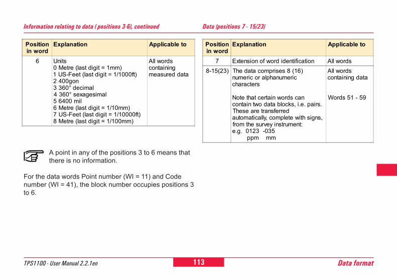
113TPS1100 - User Manual 2.2.1en Data format
6
10
12
21
26
45
84
Information relating to data ( positions 3-6), continued
A point in any of the positions 3 to 6 means thatthere is no information.
For the data words Point number (WI = 11) and Codenumber (WI = 41), the block number occupies positions 3to 6.
Data (positions 7 - 15/23)
Positionin word
Explanation Applicable to
6 Units0 Metre (last digit = 1mm)1 US-Feet (last digit = 1/1000ft)2 400gon3 360° decimal4 360° sexagesimal5 6400 mil6 Metre (last digit = 1/10mm)7 US-Feet (last digit = 1/10000ft)8 Metre (last digit = 1/100mm)
All wordscontainingmeasured data
Positionin word
Explanation Applicable to
7 Extension of word identification All words8-15(23) The data comprises 8 (16)
numeric or alphanumericcharacters
Note that certain words cancontain two data blocks, i.e. pairs.These are transferredautomatically, complete with signs,from the survey instrument:e.g. 0123 -035 ppm mm
All wordscontaining data
Words 51 - 59
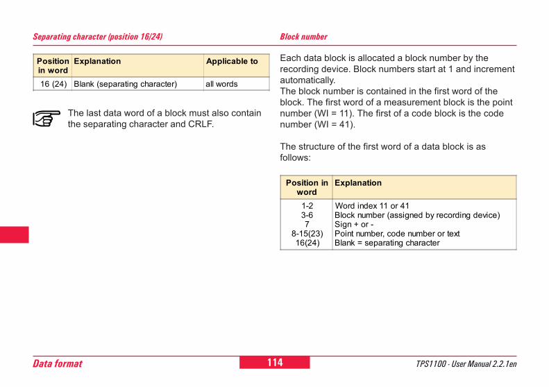
114Data format TPS1100 - User Manual 2.2.1en
6
0
2
21
26
45
84
Separating character (position 16/24)
The last data word of a block must also containthe separating character and CRLF.
Each data block is allocated a block number by therecording device. Block numbers start at 1 and incrementautomatically.The block number is contained in the first word of theblock. The first word of a measurement block is the pointnumber (WI = 11). The first of a code block is the codenumber (WI = 41).
The structure of the first word of a data block is asfollows:
Block number
Positionin word
Explanation Applicable to
16 (24) Blank (separating character) all words
Position inword
Explanation
1-23-67
8-15(23)16(24)
Word index 11 or 41Block number (assigned by recording device)Sign + or -Point number, code number or textBlank = separating character
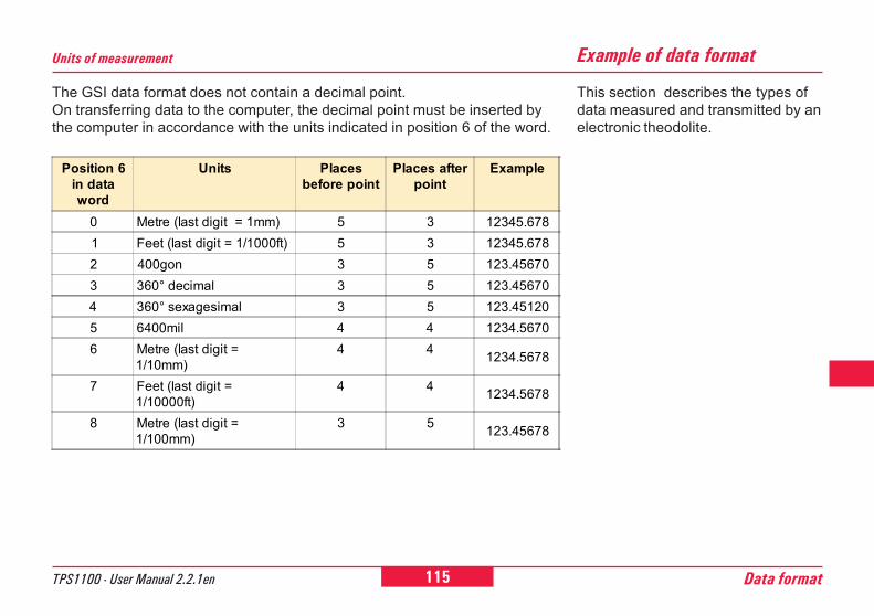
115TPS1100 - User Manual 2.2.1en Data format
6
10
12
21
26
45
84
The GSI data format does not contain a decimal point.On transferring data to the computer, the decimal point must be inserted bythe computer in accordance with the units indicated in position 6 of the word.
Units of measurement
This section describes the types ofdata measured and transmitted by anelectronic theodolite.
Example of data format
Position 6in dataword
Units Placesbefore point
Places afterpoint
Example
0 Metre (last digit = 1mm) 5 3 12345.6781 Feet (last digit = 1/1000ft) 5 3 12345.6782 400gon 3 5 123.456703 360° decimal 3 5 123.456704 360° sexagesimal 3 5 123.451205 6400mil 4 4 1234.56706 Metre (last digit =
1/10mm)4 4 1234.5678
7 Feet (last digit =1/10000ft)
4 4 1234.5678
8 Metre (last digit =1/100mm)
3 5 123.45678
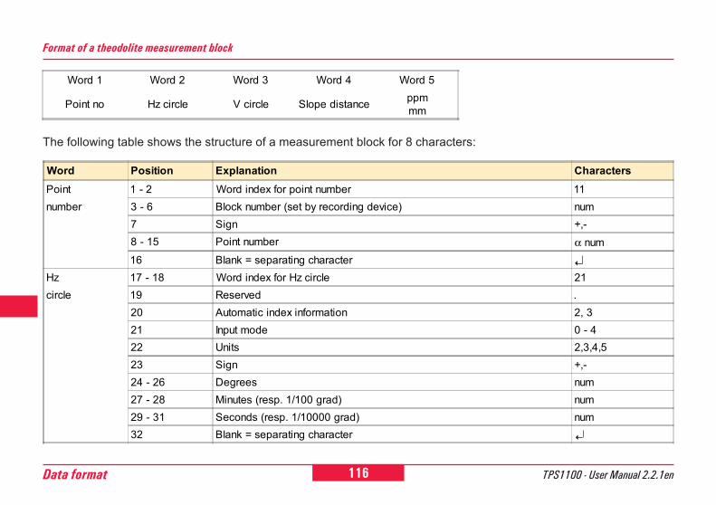
116Data format TPS1100 - User Manual 2.2.1en
6
0
2
21
26
45
84
Word Position Explanation CharactersPoint 1 - 2 Word index for point number 11number 3 - 6 Block number (set by recording device) num
7 Sign +,-8 - 15 Point number α num16 Blank = separating character
Hz 17 - 18 Word index for Hz circle 21circle 19 Reserved .
20 Automatic index information 2, 321 Input mode 0 - 422 Units 2,3,4,523 Sign +,-24 - 26 Degrees num27 - 28 Minutes (resp. 1/100 grad) num29 - 31 Seconds (resp. 1/10000 grad) num32 Blank = separating character
The following table shows the structure of a measurement block for 8 characters:
Format of a theodolite measurement block
Word 1 Word 2 Word 3 Word 4 Word 5
Point no Hz circle V circle Slope distance ppmmm
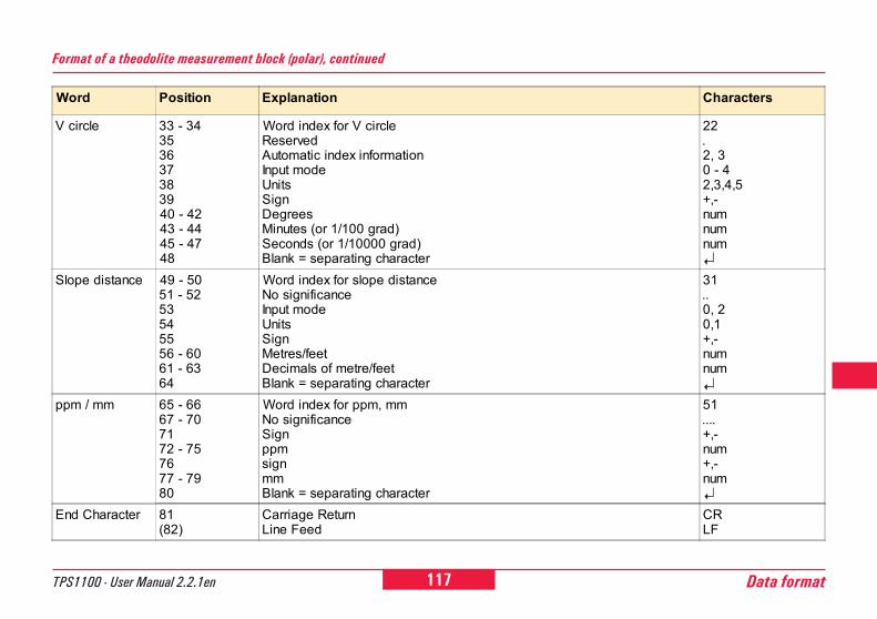
117TPS1100 - User Manual 2.2.1en Data format
6
10
12
21
26
45
84
Word Position Explanation Characters
V circle 33 - 34353637383940 - 4243 - 4445 - 4748
Word index for V circleReservedAutomatic index informationInput modeUnitsSignDegreesMinutes (or 1/100 grad)Seconds (or 1/10000 grad)Blank = separating character
22.2, 30 - 42,3,4,5+,-numnumnum
Slope distance 49 - 5051 - 5253545556 - 6061 - 6364
Word index for slope distanceNo significanceInput modeUnitsSignMetres/feetDecimals of metre/feetBlank = separating character
31..0, 20,1+,-numnum
ppm / mm 65 - 6667 - 707172 - 757677 - 7980
Word index for ppm, mmNo significanceSignppmsignmmBlank = separating character
51....+,-num+,-num
End Character 81(82)
Carriage ReturnLine Feed
CRLF
Format of a theodolite measurement block (polar), continued
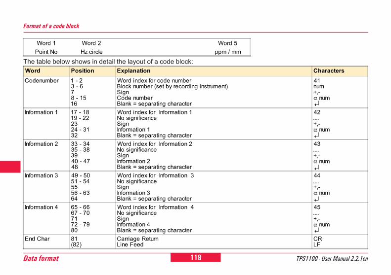
118Data format TPS1100 - User Manual 2.2.1en
6
0
2
21
26
45
84
Word Position Explanation CharactersCodenumber 1 - 2
3 - 678 - 1516
Word index for code numberBlock number (set by recording instrument)SignCode numberBlank = separating character
41num+,-α num
Information 1 17 - 1819 - 222324 - 3132
Word index for Information 1No significanceSignInformation 1Blank = separating character
42....+,-α num
Information 2 33 - 3435 - 383940 - 4748
Word index for Information 2No significanceSignInformation 2Blank = separating character
43....+,-α num
Information 3 49 - 5051 - 545556 - 6364
Word index for Information 3No significanceSignInformation 3Blank = separating character
44....+,-α num
Information 4 65 - 6667 - 707172 - 7980
Word index for Information 4No significanceSignInformation 4Blank = separating character
45....+,-α num
End Char 81(82)
Carriage ReturnLine Feed
CRLF
The table below shows in detail the layout of a code block:
Format of a code block
Word 1 Word 2 Word 5Point No Hz circle ppm / mm
119TPS1100 - User Manual 2.2.1en Care and transport
6
10
12
21
26
45
84
92
Care and transport
Transport
When transporting the instrument byrail, air or ship, always use thecomplete original packaging (caseand cardboard box), or its equivalent,to protect it against shock andvibration.
After transport, or after longperiods of storage, inspect
the field adjustment parametersgiven in this user manual beforeusing the instrument.
When dispatching theinstrument, always use the
complete original Leica Geosystemspackaging (case and cardboard box).
When transporting the instrument inthe field, always make sure that you:� either carry the instrument in its
original transportcase
� or carry the tripod with its legssplayed across yourshoulder, keeping the attachedinstrument upright.
Never carry the instrument loose in aroad vehicle. It can be affected byshock and vibration. Always carry it inits case and secure it.
An inspection of the drives in TCM,TCRM, TCA, or TCRA instrumentsmust be done in a Leica Geosystemsservice shop:� After about 4000 hours operation� Twice a year in case of permanent
use of the instrument (e.g. inmonitoring applications)
Maintainance for motorized drives

120 TPS1100 - User Manual 2.2.1enCare and transport
6
0
2
21
26
45
84
92
Cables and plugsKeep plugs clean and dry.
Blow away any dirt lodged in theplugs of the connecting cables.Unplugging connecting cables orremoving the PCMCIA card duringthe measurement may cause loss ofdata. Always switch off theinstrument before removing thecables or the PCMCIA card.
Fogging of prisms
Reflector prisms that are cooler thanthe ambient temperature tend to fog.It is not enough simply to wipe them.Keep them for some time inside yourjacket or in the vehicle to allow themto adjust to the ambient temperature.
Objective, eyepiece andprisms
� Blow dust off lenses and prisms.� Never touch the glass with your
fingers.� Use only a clean, soft, lint-free
cloth for cleaning.If necessary, moisten the cloth withpure alcohol.
Use no other liquids; these mayattack the polymer components.
Cleaning and drying
Temperature limits(-40°C to +70°C / -40°C to
+158°F) Respect the temperaturelimits when storing the instrument,particularly in summer if theinstrument is inside a vehicle.
Damp instruments must beunpacked. Dry the
instrument, the case, the foaminserts and the accessories at notmore than 40°C / 108°F and cleanthem. Do not repack until everythingis completely dry.
Storage
121TPS1100 - User Manual 2.2.1en Safety directions
6
10
12
21
26
45
84
92
Safety directionsThe following directions shouldenable the person responsible for theTPS-System 1100, and the personwho actually uses the instrument, toanticipate and avoid operationalhazards.
The person responsible for theinstrument must ensure that all usersunderstand these directions andadhere to them.
Permitted uses
The TPS-System 1100 electronictheodolites and total stations areintended for the followingapplications:
� Measuring horizontal and verticalangles
� Measuring distances (TC-modelswith integrated EDM, T-modelswith removable EDM)
� Recording measurements� Computing by means of
application software� Automatic target recognition (with
ATR)� Visualizing the aiming direction
(with EGL guide light)� Visualizing the vertical axis (with
the laser plummet).
Intended use of instrument
Prohibited uses
� Use of the product withoutinstruction
� Use outside of the intended limits� Disabling safety systems� Removal of hazard notices� Opening the instrument using tools
(screwdriver, etc.), unless this isspecifically permitted for certainfunctions
� Modification or conversion of theinstrument
� Use after misappropriation� Use with accessories from other
manufacturers without the priorexpress approval of Leica Geosy-stems
� Aiming directly into the sun� Inadequate safeguards at the
measuring station (e.g. whenmeasuring on roads)
122 TPS1100 - User Manual 2.2.1enSafety directions
6
Limits of use
Environment:Suitable for use in an atmosphereappropriate for permanent humanhabitation: not suitable for use in ag-gressive or explosive environments.Use in rain is permissible for limitedperiods.
See chapter "Technicalspecifications".
WARNING:Adverse use can lead toinjury, malfunction, and
damage. It is the task of the personresponsible for the instrument toinform the user about hazards andhow to counteract them. The totalstation is not to be operated until theuser has been instructed how to workwith it.
� Controlling machines, orcontrolling moving objects orsimilar, with the automatic targetrecognition ATR.
� Deliberate dazzling of third parties
Prohibited uses, continued

123TPS1100 - User Manual 2.2.1en Safety directions
6
10
12
21
26
45
84
92
Responsibilities
Area of responsibility for themanufacturer of the originalequipment:Leica Geosystems AG, CH-9435Heerbrugg (hereinafter referred toas Leica Geosystems):Leica Geosystems is responsible forsupplying the product, including theuser manual and originalaccessories, in a completely-safecondition.
Responsibilities of themanufacturers of non-Leica Geo-systems accessories:
The manufacturers of non-Leica Geosystems
accessories for the total stations areresponsible for developing,implementing and communicatingsafety concepts for their products,and are also responsible for theeffectiveness of those safetyconcepts in combination with the Lei-ca Geosystems product.
Responsibilities of the person incharge of the instrument:
WARNING:The person responsible forthe instrument must ensure
that it is used in accordance with theinstructions. This person is alsoaccountable for the training and thedeployment of personnel who use theinstrument and for the safety of theequipment in use.
The person in charge of theinstrument has the followingduties:� To understand the safety
instructions on the productand the instructions in the usermanual;
� To be familiar with local regulationsrelating toaccident prevention;
� To inform Leica Geosystemsimmediately if the equipmentbecomes unsafe.
Hazards of use
Main hazards of use
WARNING:The absence of instruction,or the inadequate imparting
of instruction, can lead to incorrect oradverse use, and can give rise toaccidents with far-reaching human,material, financial, and environmentalconsequences.Precautions:All users must follow the safetydirections given by the manufacturerand the directions of the personresponsible for the instrument.
124 TPS1100 - User Manual 2.2.1enSafety directions
6 CAUTION:Watch out for erroneousdistance measurements if
the product is defective or if it hasbeen dropped or has been misusedor modified.Precautions:Periodically carry out testmeasurements and perform the fieldadjustments indicated in the usermanual, particularly after theinstrument has been subjected to ab-normal use and before and afterimportant measurements.
WARNING:The charger must not beused under damp or
inclement conditions. If moisturepenetrates these devices, the usermay receive an electric shock.Precautions:Use the charger and the PCMCIA-card reader only indoors, in dryrooms. Protect them from damp. Ifthe devices are damp, do not usethem.
Main hazards of use, continued
WARNING:If you open the charger,either of the following actions
may cause you to receive an electricshock:� Touching live components;� Using the devices after incorrect
attempts to carryout repairs.
Precautions:Do not open the charger yourself.Only a Leica Geosystems -approvedservice technician is entitled to repairit.
125TPS1100 - User Manual 2.2.1en Safety directions
6
10
12
21
26
45
84
92
Main hazards of use/, continued
DANGER:Because of the risk ofelectrocution, it is very
dangerous to use reflector poles andextensions in the vicinity of electricalinstallations such as power cables orelectrical railways.Precautions:Keep at a safe distance fromelectrical installations. If it is essentialto work in this environment, firstcontact the safety authoritiesresponsible for the electricalinstallations and follow theirinstructions.
WARNING:By surveying during athunderstorm you are at risk
from lightning.Precautions:Do not carry out field surveys duringthunderstorms.
CAUTION:Be careful when pointing atotal station towards the sun,
because the telescope functions as aburning glass and can injure youreyes and/or cause damage inside theEDM or the EGL light guide.Precautions:Do not point the telescope directly atthe sun.
WARNING:During target recognition orstakeout procedures there is
a danger of accidents occurring if theuser does not pay attention to the en-vironmental conditions around orbetween the instrument and thetarget (e.g. obstacles, excavations ortraffic).Precautions:The person responsible for theinstrument must make all users fullyaware of the existing dangers.
WARNING:Inadequate securing of thesurveying site can lead to
dangerous situations, for example intraffic, on building sites, and atindustrial installations.Precautions:Always ensure that the survey site isadequately secured. Adhere to theregulations governing accidentprevention and road traffic.
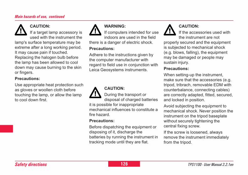
126 TPS1100 - User Manual 2.2.1enSafety directions
6 CAUTION:If a target lamp accessory isused with the instrument the
lamp's surface temperature may beextreme after a long working period.It may cause pain if touched.Replacing the halogen bulb beforethe lamp has been allowed to cooldown may cause burning to the skinor fingers.Precautions:Use appropriate heat protection suchas gloves or woollen cloth beforetouching the lamp, or allow the lampto cool down first.
Main hazards of use, continued
WARNING:If computers intended for useindoors are used in the field
there is a danger of electric shock.Precautions:Adhere to the instructions given bythe computer manufacturer withregard to field use in conjunction withLeica Geosystems instruments.
CAUTION:During the transport ordisposal of charged batteries
it is possible for inappropriatemechanical influences to constitute afire hazard.Precautions:Before dispatching the equipment ordisposing of it, discharge thebatteries by running the instrument intracking mode until they are flat.
CAUTION:If the accessories used withthe instrument are not
properly secured and the equipmentis subjected to mechanical shock(e.g. blows, falling), the equipmentmay be damaged or people maysustain injury.Precautions:When setting-up the instrument,make sure that the accessories (e.g.tripod, tribrach, removable EDM withcounterbalance, connecting cables)are correctly adapted, fitted, secured,and locked in position.Avoid subjecting the equipment tomechanical shock. Never position theinstrument on the tripod baseplatewithout securely tightening thecentral fixing screw.If the screw is loosened, alwaysremove the instrument immediatelyfrom the tripod.

127TPS1100 - User Manual 2.2.1en Safety directions
6
10
12
21
26
45
84
92
Laser classification
CAUTION:Only Leica Geosystems -authorized workshops are
entitled to repair these products.
WARNING:If the equipment isimproperly disposed of, the
following can happen:� If polymer parts are burnt,
poisonous gases areproduced which may impair health
� If batteries are damaged or areheated strongly, theycan explode and cause poisoning,burning, corrosion, or environmen-tal contamination.
� By disposing of the equipmentirresponsibly youmay enable unauthorized personsto use it in contravention of theregulations, exposing themselvesand third parties to the risk ofsevere injury and rendering theenvironment liable tocontamination
� Leakage of silicone oil from thecompensator candamage the optical and electronicsubassemblies.
Precautions:Dispose of the equipmentappropriately in accordance with theregulations in force in your country.Always prevent access to theequipment by unauthorizedpersonnel.
Main hazards of use, continued
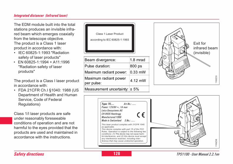
128 TPS1100 - User Manual 2.2.1enSafety directions
6
Integrated distancer (infrared laser)
The EDM module built into the totalstations produces an invisible infra-red beam which emerges coaxiallyfrom the telescope objective.The product is a Class 1 laserproduct in accordance with:� IEC 60825-1:1993 "Radiation
safety of laser products"• EN 60825-1:1994 + A11:1996
"Radiation safety of laserproducts"
The product is a Class I laser productin accordance with:� FDA 21CFR Ch.I §1040: 1988 (US
Department of Health and HumanService, Code of FederalRegulations)
Class 1/I laser products are safeunder reasonably foreseeableconditions of operation and are notharmful to the eyes provided that theproducts are used and maintained inaccordance with the instructions.
Exit forinfrared beam(invisible)
1100
Z33
1100
Z38
Type: TC..... Art.No.: ......Power: 12V/6V ---, 1A maxLeica Geosystems AGCH-9435 HeerbruggManufactured:1998Made in Switzerland S.No.: ......This laser product complies with 21CFR 1040as applicable.This device complies with part 15 of the FCCRules. Operation is subject to the following twoconditions: (1) This device may not cause harm-ful interference, and (2) this device must acceptany interference received, including inter-ference that may cause undesired operation.
Beam divergence: 1.8 mradPulse duration: 800 psMaximum radiant power: 0.33 mWMaximum radiant powerper pulse: 4.12 mW
Measurement uncertainty: ± 5%
Class 1 Laser Product
according to IEC 60825-1:1993

129TPS1100 - User Manual 2.2.1en Safety directions
6
10
12
21
26
45
84
92
Integrated distancer (visible laser)
As an alternative to the infraredbeam, the EDM incorporated into thetotal station produces a visible redlaser beam which emerges from thetelescope objective.
WARNING:Two types of distancers withvisible laser are available:
� Total stations with distancers oflaser class 3R resp. IIIa -identifiable by:� the type plate in the battery
compartment with note to"+Reflectorless Ext. Range",
� a laser emission indicator lampon the eyepiece side of thetelescope cover,
� a warning label below thememory card compartment: "La-ser class 3R" and "Class IIIaLASER PRODUCT".
� Total stations with distancers oflaser class 2 resp. II - identifiableby:� the type plate in the battery
compartment without note to"+Reflectorless Ext. Range",
� a warning label below thememory card compartment: "La-ser class 2" and "Class II LA-SER PRODUCT".
Products with an integrateddistancer of laser class 3R resp.IIIa
The product is a Class 3R laserproduct in accordance with:� IEC 60825-1:1993 + A1:1997 +
A2:2001 : "Radiation safety oflaser products"
The product is a Class IIIa laserproduct in accordance with:� FDA 21CFR Ch.I §1040 : 1988
(US Department of Health andHuman Service, Code of FederalRegulations).
Class 3R / IIIa laser products:Direct intrabeam viewing is alwayshazardous. Avoid direct eye exposure.The accessible emission limit iswithin five times the accessibleemission limits of Class 2 / II in thewavelength range from 400nm to700nm.
130 TPS1100 - User Manual 2.2.1enSafety directions
6
Integrated distancer (visible laser), continued
WARNING:Direct intrabeam viewing isalways hazardous.
Precautions:Do not stare into the beam or direct ittowards other people unnecessarily.These measures are also valid forthe reflected beam.
WARNING:Looking directly into thereflected laser beam could
be dangerous to the eyes when thelaser beam is aimed at areas thatreflect like a mirror or emit reflectionsunexpectedly (e.g. prisms, mirrors,metallic surfaces, windows).Precautions:Do not aim at areas that areessentially reflective, such as amirror, or which could emit unwantedreflections. Do not look through orbeside the optical sight at prisms orreflecting objects when the laser isswitched on (in Laserpointer ordistance measurement mode).Aiming at prisms is only permittedwhen looking through the telescope.
WARNING:The use of Laser Class 3R /IIIa equipment can be
dangerous.Precautions:To counteract hazards, it is essentialfor every user to respect the safetyprecautions and control measuresspecified in the standard IEC 60825-1:1993 + A1:1997 + A2:2001, within thehazard distance *). Pay particularattention to Section Three "User'sGuide".
131TPS1100 - User Manual 2.2.1en Safety directions
6
10
12
21
26
45
84
92
Integrated distancer (visible laser), continued
There follows here below aninterpretation of the main points inthe relevant section of the standardquoted.
Class 3R laser products used onconstruction sites and outdoors(surveying, alignment, levelling):
a) Only qualified and trained personsshould be assigned to install,adjust and operate the laserequipment.
b) Areas in which these lasers areused should be posted with anappropriate laser warning sign.
c) Precautions should be taken toensure that persons do not lookdirectly, with or without an opticalinstrument, into the beam.
d) The laser beam should beterminated at the end of its usefulbeam path and should in all casesbe terminated if the hazardousbeam path extends beyond thelimit (hazard distance *)) of thearea in which the presence andactivities of personnel aremonitored for reasons ofprotection from laser radiation.
e) The laser beam path should belocated well above or below eyelevel wherever practicable.
f) When not in use the laser productshould be stored in a locationwhere unauthorized personnelcannot gain access.
g) Precautions should be taken toensure that the laser beam is notunintentionally directed at mirror-like (specular) surfaces (e.g.mirrors, metal surfaces, windows).But, more importantly, at flat orconcave mirror-like surfaces.
*) The hazard distance is thedistance from the laser at whichbeam irradiance or radiantexposure equals the maximumpermissible value to whichpersonnel may be exposed withoutbeing exposed to a health risk.
Products with an integrated distancerof laser class 3R resp. IIIa thishazard distance is 1000m (3300ft). Atthis distance, the laser beam rates asClass 1 (= direct intrabeam viewing isnot hazardous).
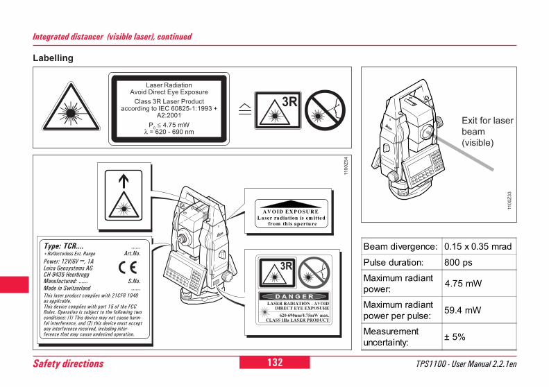
132 TPS1100 - User Manual 2.2.1enSafety directions
6
Integrated distancer (visible laser), continued
Beam divergence: 0.15 x 0.35 mrad
Pulse duration: 800 psMaximum radiantpower: 4.75 mW
Maximum radiantpower per pulse: 59.4 mW
Measurementuncertainty: ± 5%
Labelling
Exit for laserbeam(visible)
1100
Z33
1100
Z54
Type: TCR.... ......+Reflectorless Ext. Range Art.No.Power: 12V/6V ---, 1ALeica Geosystems AGCH-9435 HeerbruggManufactured: ...... S.No.Made in Switzerland ......This laser product complies with 21CFR 1040as applicable.This device complies with part 15 of the FCCRules. Operation is subject to the following twoconditions: (1) This device may not cause harm-ful interference, and (2) this device must acceptany interference received, including inter-ference that may cause undesired operation.
A V O ID EX P O SU R ELaser radiation is em itted from this apertu re
Laser RadiationAvoid Direct Eye Exposure
Class 3R Laser Productaccording to IEC 60825-1:1993 +
A2:2001P0 ≤ 4.75 mW
λ = 620 - 690 nm
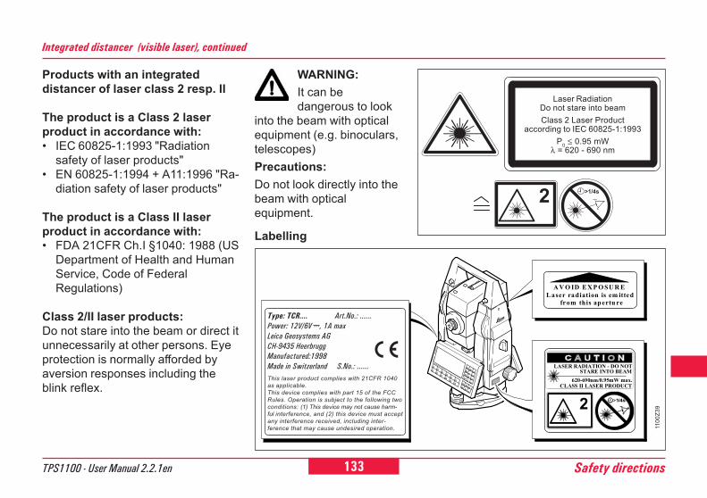
133TPS1100 - User Manual 2.2.1en Safety directions
6
10
12
21
26
45
84
92
WARNING:It can bedangerous to look
into the beam with opticalequipment (e.g. binoculars,telescopes)Precautions:Do not look directly into thebeam with opticalequipment.
Labelling
Products with an integrateddistancer of laser class 2 resp. II
The product is a Class 2 laserproduct in accordance with:� IEC 60825-1:1993 "Radiation
safety of laser products"� EN 60825-1:1994 + A11:1996 "Ra-
diation safety of laser products"
The product is a Class II laserproduct in accordance with:� FDA 21CFR Ch.I §1040: 1988 (US
Department of Health and HumanService, Code of FederalRegulations)
Class 2/II laser products:Do not stare into the beam or direct itunnecessarily at other persons. Eyeprotection is normally afforded byaversion responses including theblink reflex.
Integrated distancer (visible laser), continued
A V O ID EX P O SU R ELaser radiation is em itted from this apertu re
1100
Z39
Type: TCR.... Art.No.: ......Power: 12V/6V ---, 1A maxLeica Geosystems AGCH-9435 HeerbruggManufactured:1998Made in Switzerland S.No.: ......This laser product complies with 21CFR 1040as applicable.This device complies with part 15 of the FCCRules. Operation is subject to the following twoconditions: (1) This device may not cause harm-ful interference, and (2) this device must acceptany interference received, including inter-ference that may cause undesired operation.
1/4s
LASER RADIATION - DO NOT
620-690nm/0.95mW max.CLASS II LASER PRODUCT
STARE INTO BEAM
2
Laser RadiationDo not stare into beamClass 2 Laser Product
according to IEC 60825-1:1993P0 ≤ 0.95 mW
λ = 620 - 690 nm
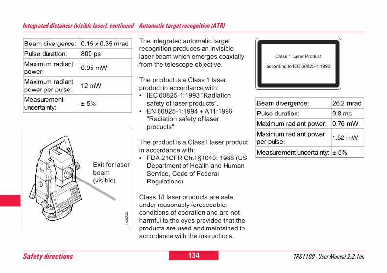
134 TPS1100 - User Manual 2.2.1enSafety directions
6
Exit for laserbeam(visible)
Integrated distancer (visible laser), continued
1100
Z33
Automatic target recognition (ATR)
The integrated automatic targetrecognition produces an invisiblelaser beam which emerges coaxiallyfrom the telescope objective.
The product is a Class 1 laserproduct in accordance with:� IEC 60825-1:1993 "Radiation
safety of laser products".� EN 60825-1:1994 + A11:1996
"Radiation safety of laserproducts"
The product is a Class I laser productin accordance with:� FDA 21CFR Ch.I §1040: 1988 (US
Department of Health and HumanService, Code of FederalRegulations)
Class 1/I laser products are safeunder reasonably foreseeableconditions of operation and are notharmful to the eyes provided that theproducts are used and maintained inaccordance with the instructions.
Beam divergence: 0.15 x 0.35 mradPulse duration: 800 psMaximum radiantpower: 0.95 mW
Maximum radiantpower per pulse: 12 mW
Measurementuncertainty: ± 5% Beam divergence: 26.2 mrad
Pulse duration: 9.8 msMaximum radiant power: 0.76 mWMaximum radiant powerper pulse: 1.52 mW
Measurement uncertainty: ± 5%
Class 1 Laser Product
according to IEC 60825-1:1993
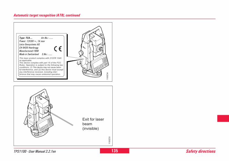
135TPS1100 - User Manual 2.2.1en Safety directions
6
10
12
21
26
45
84
92
Automatic target recognition (ATR), continued
Exit for laserbeam(invisible)
1100
Z33
1100
Z34
Type: TCA.... Art.No.: ......Power: 12V/6V ---, 1A maxLeica Geosystems AGCH-9435 HeerbruggManufactured:1998Made in Switzerland S.No.: ......This laser product complies with 21CFR 1040as applicable.This device complies with part 15 of the FCCRules. Operation is subject to the following twoconditions: (1) This device may not cause harm-ful interference, and (2) this device must acceptany interference received, including inter-ference that may cause undesired operation.
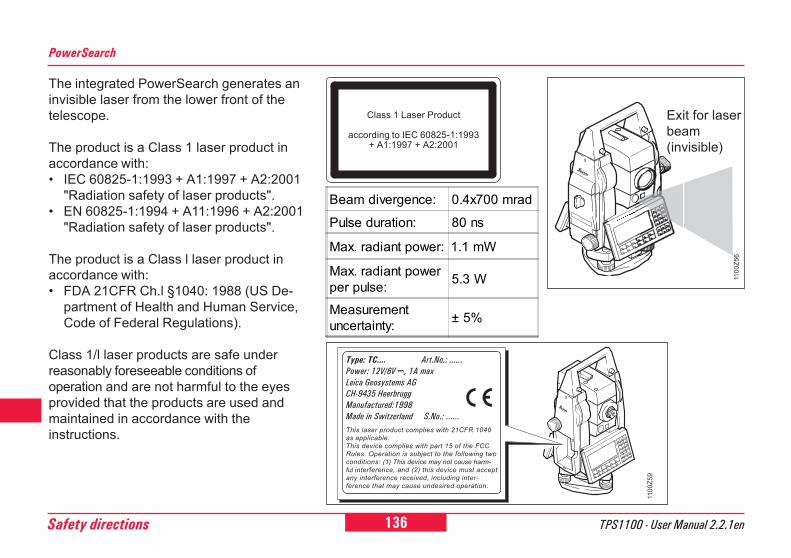
136 TPS1100 - User Manual 2.2.1enSafety directions
6
PowerSearch
The integrated PowerSearch generates aninvisible laser from the lower front of thetelescope.
The product is a Class 1 laser product inaccordance with:� IEC 60825-1:1993 + A1:1997 + A2:2001
"Radiation safety of laser products".� EN 60825-1:1994 + A11:1996 + A2:2001
"Radiation safety of laser products".
The product is a Class l laser product inaccordance with:� FDA 21CFR Ch.l §1040: 1988 (US De-
partment of Health and Human Service,Code of Federal Regulations).
Class 1/l laser products are safe underreasonably foreseeable conditions ofoperation and are not harmful to the eyesprovided that the products are used andmaintained in accordance with theinstructions.
1100
Z56
Exit for laserbeam(invisible)
Class 1 Laser Product
according to IEC 60825-1:1993+ A1:1997 + A2:2001
1100
Z59
Type: TC.... Art.No.: ......Power: 12V/6V ---, 1A maxLeica Geosystems AGCH-9435 HeerbruggManufactured:1998Made in Switzerland S.No.: ......This laser product complies with 21CFR 1040as applicable.This device complies with part 15 of the FCCRules. Operation is subject to the following twoconditions: (1) This device may not cause harm-ful interference, and (2) this device must acceptany interference received, including inter-ference that may cause undesired operation.
Beam divergence: 0.4x700 mrad
Pulse duration: 80 ns
Max. radiant power: 1.1 mW
Max. radiant powerper pulse: 5.3 W
Measurementuncertainty: ± 5%
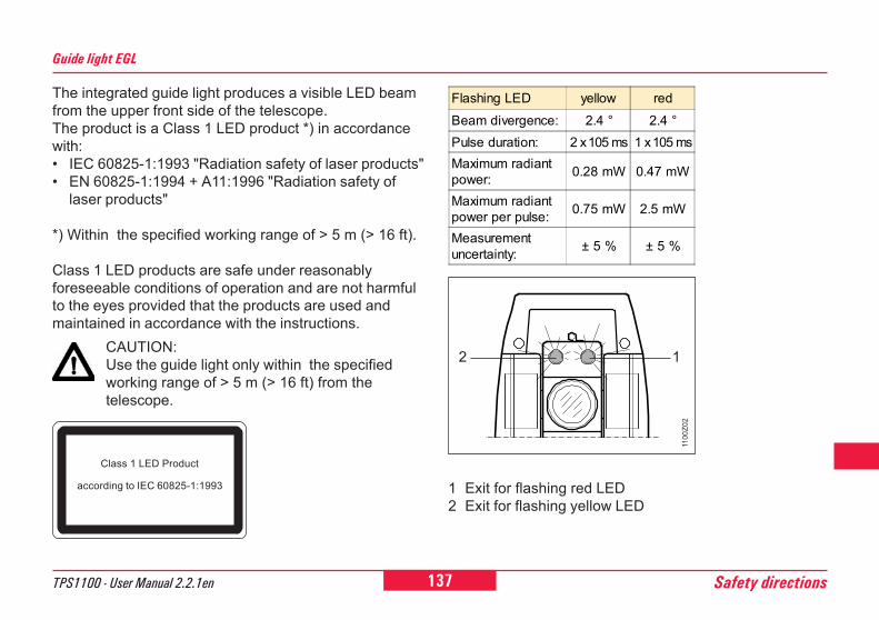
137TPS1100 - User Manual 2.2.1en Safety directions
6
10
12
21
26
45
84
92
The integrated guide light produces a visible LED beamfrom the upper front side of the telescope.The product is a Class 1 LED product *) in accordancewith:� IEC 60825-1:1993 "Radiation safety of laser products"� EN 60825-1:1994 + A11:1996 "Radiation safety of
laser products"
*) Within the specified working range of > 5 m (> 16 ft).
Class 1 LED products are safe under reasonablyforeseeable conditions of operation and are not harmfulto the eyes provided that the products are used andmaintained in accordance with the instructions.
Guide light EGL
CAUTION:Use the guide light only within the specifiedworking range of > 5 m (> 16 ft) from thetelescope.
Class 1 LED Product
according to IEC 60825-1:1993 1 Exit for flashing red LED2 Exit for flashing yellow LED
1100
Z02
2 1
Flashing LED yellow redBeam divergence: 2.4 ° 2.4 °Pulse duration: 2 x 10⁵ ms 1 x 10⁵ msMaximum radiantpower: 0.28 mW 0.47 mW
Maximum radiantpower per pulse: 0.75 mW 2.5 mW
Measurementuncertainty: ± 5 % ± 5 %
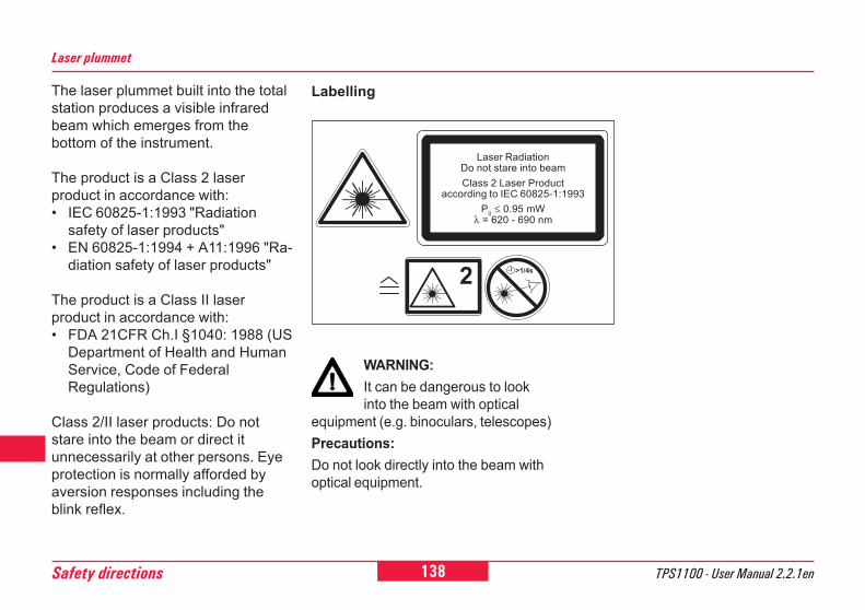
138 TPS1100 - User Manual 2.2.1enSafety directions
6 The laser plummet built into the totalstation produces a visible infraredbeam which emerges from thebottom of the instrument.
The product is a Class 2 laserproduct in accordance with:� IEC 60825-1:1993 "Radiation
safety of laser products"� EN 60825-1:1994 + A11:1996 "Ra-
diation safety of laser products"
The product is a Class II laserproduct in accordance with:� FDA 21CFR Ch.I §1040: 1988 (US
Department of Health and HumanService, Code of FederalRegulations)
Class 2/II laser products: Do notstare into the beam or direct itunnecessarily at other persons. Eyeprotection is normally afforded byaversion responses including theblink reflex.
Laser plummet
Labelling
WARNING:It can be dangerous to lookinto the beam with optical
equipment (e.g. binoculars, telescopes)Precautions:Do not look directly into the beam withoptical equipment.
Laser RadiationDo not stare into beamClass 2 Laser Product
according to IEC 60825-1:1993P0 ≤ 0.95 mW
λ = 620 - 690 nm
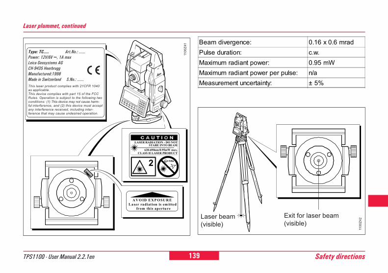
139TPS1100 - User Manual 2.2.1en Safety directions
6
10
12
21
26
45
84
92
Laser plummet, continued
1100
Z42
Beam divergence: 0.16 x 0.6 mradPulse duration: c.w.Maximum radiant power: 0.95 mWMaximum radiant power per pulse: n/aMeasurement uncertainty: ± 5%
Exit for laser beam(visible)
Laser beam(visible)
A V O ID EX P O SU R ELaser radiation is em itted from this apertu re
1100
Z41
1/4s
LASER RADIATION - DO NOT
620-690nm/0.95mW max.CLASS II LASER PRODUCT
STARE INTO BEAM
2
Type: TC..... Art.No.: ......Power: 12V/6V ---, 1A maxLeica Geosystems AGCH-9435 HeerbruggManufactured:1998Made in Switzerland S.No.: ......This laser product complies with 21CFR 1040as applicable.This device complies with part 15 of the FCCRules. Operation is subject to the following twoconditions: (1) This device may not cause harm-ful interference, and (2) this device must acceptany interference received, including inter-ference that may cause undesired operation.
140 TPS1100 - User Manual 2.2.1enSafety directions
6
Electromagnetic Compatibility (EMC)
WARNING:Electromagnetic radiationcan cause disturbances in
other equipment.
Although the total stations meet thestrict regulations and standardswhich are in force in this respect, Lei-ca Geosystems cannot completelyexclude the possibility that otherequipment may be disturbed.
CAUTION:There is a risk thatdisturbances may be caused
in other equipment if the total stationis used in conjunction withaccessories from othermanufacturers, e.g. field computers,personal computers, walkie-talkies,non-standard cables, externalbatteries.Precautions:Use only the equipment andaccessories recommended by LeicaGeosystems. When combined withtotal stations, they meet the strictrequirements stipulated by theguidelines and standards. Whenusing computers and walkie-talkies,pay attention to the information aboutelectromagnetic compatibilityprovided by the manufacturer.
The term "electromagneticcompatibility" is taken to mean thecapability of the total station tofunction smoothly in an environmentwhere electromagnetic radiation andelectrostatic discharges are present,and without causing electromagneticdisturbances to other equipment.
141TPS1100 - User Manual 2.2.1en Safety directions
6
10
12
21
26
45
84
92
CAUTION:Disturbances caused byelectromagnetic radiation can
result in the tolerance limits formeasurements being exceeded.
Although the total stations meet thestrict regulations and standardswhich are in force in this connection,Leica Geosystems cannot completelyexclude the possibility that the totalstation may be disturbed by veryintense electromagnetic radiation,e.g. near radio transmitters, walkie-talkies, diesel generators, powercables.Check the plausibility of resultsobtained under these conditions.
Electromagnetic Compatibility, continued
WARNING:If the total station is operatedwith connecting cables
attached at only one of their two ends(e.g. external supply cables, interfacecables), the permitted level ofelectromagnetic radiation may beexceeded and the correct functioningof other instruments may beimpaired.Precautions:While the total station is in use,connecting cables (e.g. instrument toexternal battery, instrument tocomputer) must be connected at bothends.
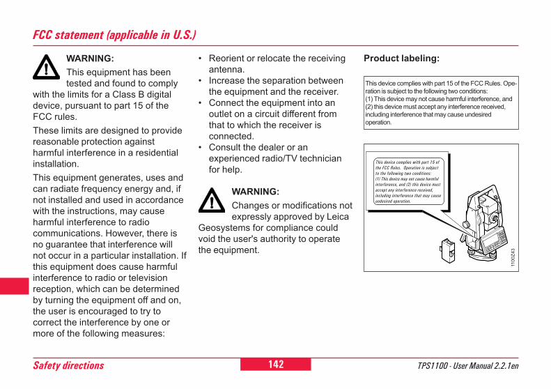
142 TPS1100 - User Manual 2.2.1enSafety directions
6
FCC statement (applicable in U.S.)
WARNING:This equipment has beentested and found to comply
with the limits for a Class B digitaldevice, pursuant to part 15 of theFCC rules.These limits are designed to providereasonable protection againstharmful interference in a residentialinstallation.This equipment generates, uses andcan radiate frequency energy and, ifnot installed and used in accordancewith the instructions, may causeharmful interference to radiocommunications. However, there isno guarantee that interference willnot occur in a particular installation. Ifthis equipment does cause harmfulinterference to radio or televisionreception, which can be determinedby turning the equipment off and on,the user is encouraged to try tocorrect the interference by one ormore of the following measures:
This device complies with part 15 of the FCC Rules. Ope-ration is subject to the following two conditions:(1) This device may not cause harmful interference, and(2) this device must accept any interference received,including interference that may cause undesiredoperation.
Product labeling:� Reorient or relocate the receivingantenna.
� Increase the separation betweenthe equipment and the receiver.
� Connect the equipment into anoutlet on a circuit different fromthat to which the receiver isconnected.
� Consult the dealer or anexperienced radio/TV technicianfor help.
WARNING:Changes or modifications notexpressly approved by Leica
Geosystems for compliance couldvoid the user's authority to operatethe equipment.
1100
Z43
This device complies with part 15 ofthe FCC Rules. Operation is subjectto the following two conditions:(1) This device may not cause harmfulinterference, and (2) this device mustaccept any interference received,including interference that may causeundesired operation.
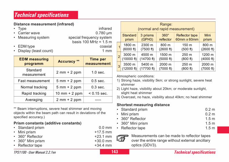
143TPS1100 - User Manual 2.2.1en Technical specifications
6
10
12
21
26
45
84
92
Standardprism
3 prisms(GPH3)
360°reflector
Reflector tape60mm x 60mm
Miniprism
1 1800 m(6000 ft)
2300 m(7500 ft)
800 m(2600 ft)
150 m(500 ft)
800 m(2600 ft)
2 3000 m(10000 ft)
4500 m(14700 ft)
1500 m(5000 ft)
250 m(800 ft)
1200 m(4000 ft)
3 3500 m(12000 ft)
5400 m(17700 ft)
2000 m(7000 ft)
250 m(800 ft)
2000 m(7000 ft)
Technical specificationsDistance measurement (infrared)� Type infrared� Carrier wave 0.780 µm� Measuring system special frequency system
basis 100 MHz = 1.5 m� EDM type coaxial� Display (least count) 1 mm
Atmospheric conditions:1) Strong haze, visibility 5km; or strong sunlight, severe heat
shimmer2) Light haze, visibility about 20km; or moderate sunlight,
slight heat shimmer3) Overcast, no haze, visibility about 40km; no heat shimmer
Shortest measuring distance� Standard prism 0.2 m� Mini prism 0.2 m� 360° Reflector 1.5 m� 360° Mini prism 1.5 m� Reflector tape 1.5 m
Measurements can be made to reflector tapesover the entire range without external ancillaryoptics (GDV3).
Range:(normal and rapid measurement)
Prism constants (additive constants)� Standard prism 0.0 mm� Mini prism +17.5 mm� 360° Reflector +23.1 mm� 360° Mini prism +30.0 mm� Reflector tape +34.4 mm
EDM measuringprogramm Accuracy ** Time per
measurementStandard
measurement 2 mm + 2 ppm 1.0 sec.
Fast measurement 5 mm + 2 ppm 0.5 sec.Normal tracking 5 mm + 2 ppm 0.3 sec.Rapid tracking 10 mm + 2 ppm < 0.15 sec.
Averaging 2 mm + 2 ppm -----
** Beam interruptions, severe heat shimmer and movingobjects within the beam path can result in deviations of thespecified accuracy.)
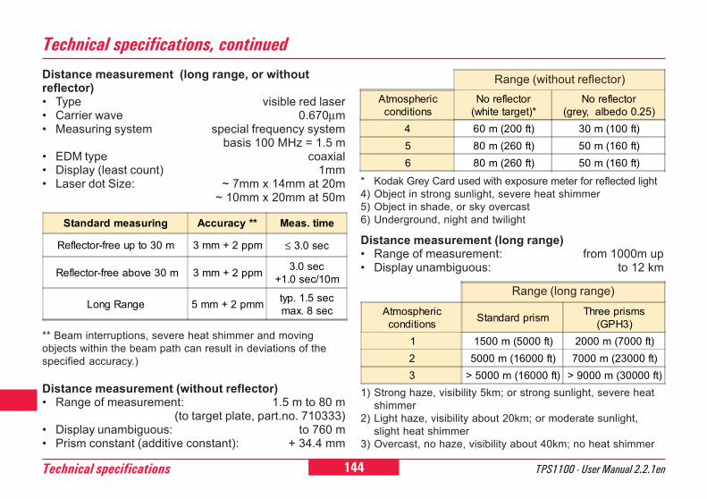
144 TPS1100 - User Manual 2.2.1enTechnical specifications
6
0
2
21
26
45
84
92
Technical specifications, continuedDistance measurement (long range, or withoutreflector)� Type visible red laser� Carrier wave 0.670µm� Measuring system special frequency system
basis 100 MHz = 1.5 m� EDM type coaxial� Display (least count) 1mm� Laser dot Size: ~ 7mm x 14mm at 20m
~ 10mm x 20mm at 50m
Atmosphericconditions
No reflector(white target)*
No reflector(grey, albedo 0.25)
4 60 m (200 ft) 30 m (100 ft)5 80 m (260 ft) 50 m (160 ft)6 80 m (260 ft) 50 m (160 ft)
Range (without reflector)
Distance measurement (without reflector)� Range of measurement: 1.5 m to 80 m
(to target plate, part.no. 710333)� Display unambiguous: to 760 m� Prism constant (additive constant): + 34.4 mm
1) Strong haze, visibility 5km; or strong sunlight, severe heatshimmer
2) Light haze, visibility about 20km; or moderate sunlight,slight heat shimmer
3) Overcast, no haze, visibility about 40km; no heat shimmer
* Kodak Grey Card used with exposure meter for reflected light4) Object in strong sunlight, severe heat shimmer5) Object in shade, or sky overcast6) Underground, night and twilight
Atmosphericconditions Standard prism Three prisms
(GPH3)1 1500 m (5000 ft) 2000 m (7000 ft)2 5000 m (16000 ft) 7000 m (23000 ft)3 > 5000 m (16000 ft) > 9000 m (30000 ft)
Range (long range)
Standard measuring Accuracy ** Meas. time
Reflector-free up to 30 m 3 mm + 2 ppm ≤ 3.0 sec
Reflector-free above 30 m 3 mm + 2 ppm 3.0 sec+1.0 sec/10m
Long Range 5 mm + 2 pmm typ. 1.5 secmax. 8 sec
Distance measurement (long range)� Range of measurement: from 1000m up� Display unambiguous: to 12 km
** Beam interruptions, severe heat shimmer and movingobjects within the beam path can result in deviations of thespecified accuracy.)
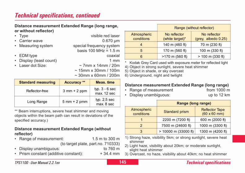
145TPS1100 - User Manual 2.2.1en Technical specifications
6
10
12
21
26
45
84
92
Technical specifications, continued
Range (long range)Atmosphericconditions Standard prism Reflector Tape
(60 x 60 mm)1 2200 m (7200 ft) 600 m (2000 ft)2 7500 m (24600 ft) 1000 m (3300 ft)3 > 10000 m (33000 ft) 1300 m (4200 ft)
Range (without reflector)
Atmosphericconditions
No reflector(white target)*
No reflector(grey, albedo 0.25)
4 140 m (460 ft) 70 m (230 ft)5 170 m (560 ft) 100 m (330 ft)6 >170 m (560 ft) > 100 m (330 ft)
Distance measurement Extended Range (long range,or without reflector)� Type visible red laser� Carrier wave 0.670 µm� Measuring system special frequency system
basis 100 MHz = 1.5 m� EDM type coaxial� Display (least count) 1 mm� Laser dot Size: ~ 7mm x 14mm / 20m
~ 15mm x 30mm / 100m~ 30mm x 60mm / 200m
** Beam interruptions, severe heat shimmer and movingobjects within the beam path can result in deviations of thespecified accuracy.)
Distance measurement Extended Range (withoutreflector)� Range of measurement: 1.5 m to 300 m
(to target plate, part.no. 710333)� Display unambiguous: to 760 m� Prism constant (additive constant): + 34.4 mm
1) Strong haze, visibility 5km; or strong sunlight, severe heatshimmer
2) Light haze, visibility about 20km; or moderate sunlight,slight heat shimmer
3) Overcast, no haze, visibility about 40km; no heat shimmer
Distance measurement Extended Range (long range)� Range of measurement from 1000 m� Display unambiguous: up to 12 km
Standard measuring Accuracy ** Meas. time
Reflector-free 3 mm + 2 ppm typ. 3 - 6 secmax. 12 sec
Long Range 5 mm + 2 pmm typ. 2.5 secmax. 8 sec
* Kodak Grey Card used with exposure meter for reflected light4) Object in strong sunlight, severe heat shimmer5) Object in shade, or sky overcast6) Underground, night and twilight
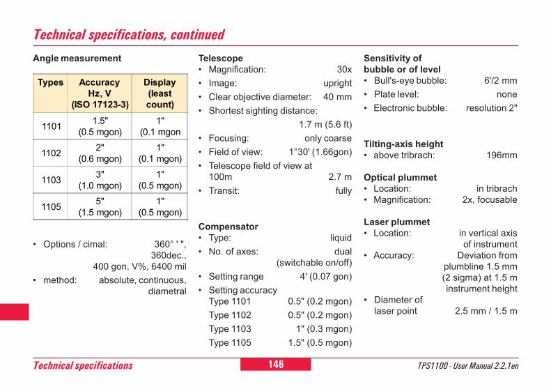
146 TPS1100 - User Manual 2.2.1enTechnical specifications
6
0
2
21
26
45
84
92
Angle measurement
Types AccuracyHz, V
(ISO 17123-3)
Display(leastcount)
1101 1.5"(0.5 mgon)
1"(0.1 mgon
1102 2"(0.6 mgon)
1"(0.1 mgon)
1103 3"(1.0 mgon)
1"(0.5 mgon)
1105 5"(1.5 mgon)
1"(0.5 mgon)
� Options / cimal: 360° ' ",360dec.,
400 gon, V%, 6400 mil� method: absolute, continuous,
diametral
Technical specifications, continuedTelescope� Magnification: 30x� Image: upright� Clear objective diameter: 40 mm� Shortest sighting distance:
1.7 m (5.6 ft)� Focusing: only coarse� Field of view: 1°30' (1.66gon)� Telescope field of view at
100m 2.7 m� Transit: fully
Compensator� Type: liquid� No. of axes: dual
(switchable on/off)� Setting range 4' (0.07 gon)� Setting accuracy
Type 1101 0.5" (0.2 mgon)Type 1102 0.5" (0.2 mgon)Type 1103 1" (0.3 mgon)Type 1105 1.5" (0.5 mgon)
Sensitivity ofbubble or of level� Bull's-eye bubble: 6'/2 mm� Plate level: none� Electronic bubble: resolution 2"
Tilting-axis height� above tribrach: 196mm
Optical plummet� Location: in tribrach� Magnification: 2x, focusable
Laser plummet� Location: in vertical axis
of instrument� Accuracy: Deviation from
plumbline 1.5 mm(2 sigma) at 1.5 minstrument height
� Diameter oflaser point 2.5 mm / 1.5 m
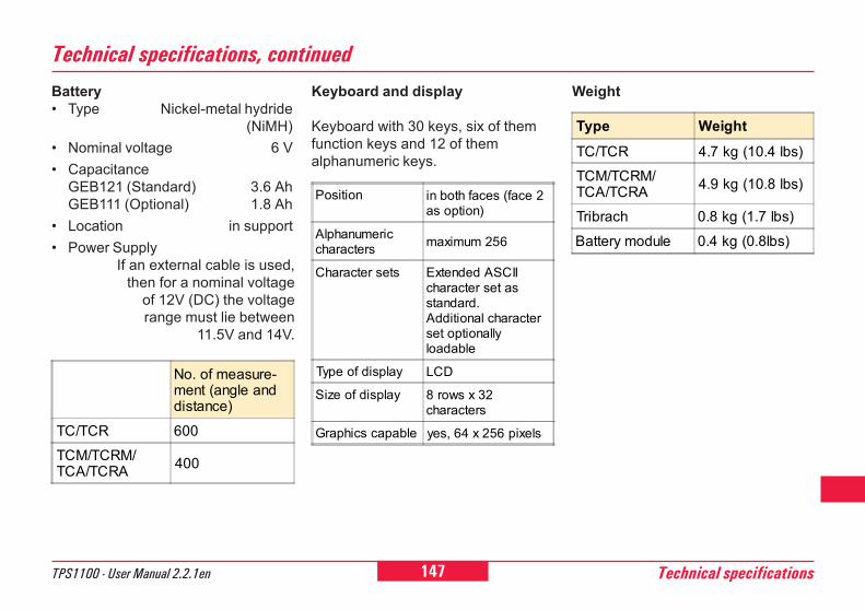
147TPS1100 - User Manual 2.2.1en Technical specifications
6
10
12
21
26
45
84
92
Technical specifications, continuedBattery� Type Nickel-metal hydride
(NiMH)� Nominal voltage 6 V� Capacitance
GEB121 (Standard) 3.6 AhGEB111 (Optional) 1.8 Ah
� Location in support� Power Supply
If an external cable is used,then for a nominal voltage
of 12V (DC) the voltagerange must lie between
11.5V and 14V.
Keyboard and display
Keyboard with 30 keys, six of themfunction keys and 12 of themalphanumeric keys.
Weight
Position in both faces (face 2as option)
Alphanumericcharacters maximum 256
Character sets Extended ASCIIcharacter set asstandard.Additional characterset optionallyloadable
Type of display LCD
Size of display 8 rows x 32characters
Graphics capable yes, 64 x 256 pixels
No. of measure-ment (angle anddistance)
TC/TCR 600TCM/TCRM/TCA/TCRA 400
Type WeightTC/TCR 4.7 kg (10.4 lbs)TCM/TCRM/TCA/TCRA 4.9 kg (10.8 lbs)
Tribrach 0.8 kg (1.7 lbs)Battery module 0.4 kg (0.8lbs)
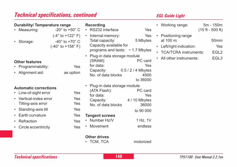
148 TPS1100 - User Manual 2.2.1enTechnical specifications
6
0
2
21
26
45
84
92
Technical specifications, continuedRecording� RS232 interface Yes� Internal memory: Yes
Total capacity: 5 MbytesCapacity available forprograms and texts: ~ 1.7 Mbytes
� Plug-in data storage module(SRAM): PC cardfor data: YesCapacity: 0.5 / 2 / 4 MbytesNo. of data blocks 4500
to 36000� Plug-in data storage module
(ATA Flash): PC cardfor data: YesCapacity: 4 / 10 MbytesNo. of data blocks 36000
to 90 000Tangent screws� Number Hz/V 1 Hz, 1V� Movement endless
Other drives� TCM, TCA motorized
Durability/ Temperature range� Measuring: -20° to +50° C
(-4° to +122° F)� Storage: -40° to +70° C
(-40° to +158° F)
Other features� Programmability: Yes� Alignment aid: as option
Automatic corrections� Line-of-sight error Yes� Vertical-index error Yes
Tilting-axis error Yes� Standing-axis tilt Yes� Earth curvature Yes� Refraction Yes� Circle eccentricity Yes
EGL Guide Light
� Working range: 5m - 150m(15 ft - 500 ft)
� Positioning rangeat 100 m: 50mm
� Left/right indication: Yes� TCA/TCRA instruments: EGL2� All other instruments: EGL3
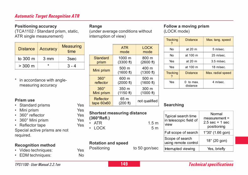
149TPS1100 - User Manual 2.2.1en Technical specifications
6
10
12
21
26
45
84
92
Automatic Target Recognition ATR
Positioning accuracy(TCA1102 / Standard prism, static,ATR single measurement)
* in accordance with angle-measuring accuracy
Prism use� Standard prisms Yes� Mini prism Yes� 360° reflector Yes� 360° Mini prism Yes� Reflector tape YesSpecial active prisms are notrequired.
Recognition method� Video techniques: Yes� EDM techniques: No
ATRmode
LOCKmode
Standardprism
1000 m(3300 ft)
800 m(2600 ft)
Mini prism 500 m(1600 ft)
400 m(1300 ft)
360°reflector
600 m(2000 ft)
500 m(1600 ft)
360°Mini prism
350 m(1150 ft)
300 m(1000 ft)
Reflectortape 60x60
65 m(200 ft) not qualified
Range(under average conditions withoutinterruption of view)
Shortest measuring distance(360°Refl.)� ATR 1.5 m� LOCK 5 m
Rotation and speedPositioning to 50 gon/sec
Follow a moving prism(LOCK mode)
Typical search timein telescopic field ofview
Normalmeasurement =2.5 sec + 1 sec
positioningFull scope of search 1°30' (1.66 gon)Scope of searchusing remote control 18° (20 gon)
Interrupted viewing Yes, briefly
Searching
Tracking?
Distance Max. tang. speed
No at 20 m 5 m/sec.
No at 100 m 25 m/sec.
Yes at 20 m 3.5 m/sec.
Yes at 100 m 18 m/sec.
Tracking?
Distance Max. radial speed
Yes 0 to max.distance
4 m/sec.
Distance Accuracy Measuringtime
to 300 m 3 mm 3sec> 300 m * 3 - 4
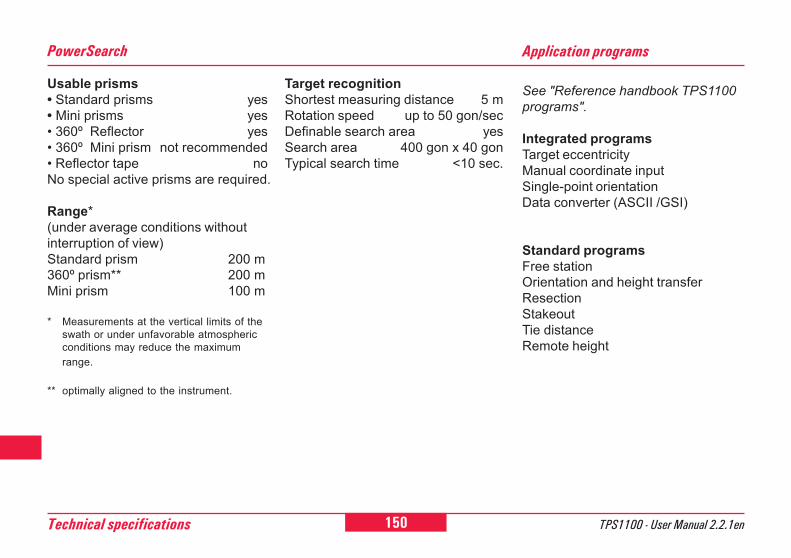
150 TPS1100 - User Manual 2.2.1enTechnical specifications
6
0
2
21
26
45
84
92
See "Reference handbook TPS1100programs".
Integrated programsTarget eccentricityManual coordinate inputSingle-point orientationData converter (ASCII /GSI)
Standard programsFree stationOrientation and height transferResectionStakeoutTie distanceRemote height
Application programsPowerSearch
Usable prisms� Standard prisms yes� Mini prisms yes� 360º Reflector yes� 360º Mini prism not recommended� Reflector tape noNo special active prisms are required.
Range*(under average conditions withoutinterruption of view)Standard prism 200 m360º prism** 200 mMini prism 100 m
* Measurements at the vertical limits of theswath or under unfavorable atmosphericconditions may reduce the maximumrange.
** optimally aligned to the instrument.
Target recognitionShortest measuring distance 5 mRotation speed up to 50 gon/secDefinable search area yesSearch area 400 gon x 40 gonTypical search time <10 sec.
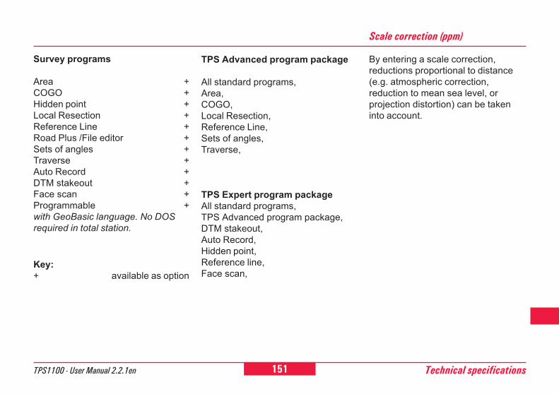
151TPS1100 - User Manual 2.2.1en Technical specifications
6
10
12
21
26
45
84
92
TPS Advanced program package
All standard programs,Area,COGO,Local Resection,Reference Line,Sets of angles,Traverse,
TPS Expert program packageAll standard programs,TPS Advanced program package,DTM stakeout,Auto Record,Hidden point,Reference line,Face scan,
Scale correction (ppm)
By entering a scale correction,reductions proportional to distance(e.g. atmospheric correction,reduction to mean sea level, orprojection distortion) can be takeninto account.
Survey programs
Area +COGO +Hidden point +Local Resection +Reference Line +Road Plus /File editor +Sets of angles +Traverse +Auto Record +DTM stakeout +Face scan +Programmable +with GeoBasic language. No DOSrequired in total station.
Key:+ available as option
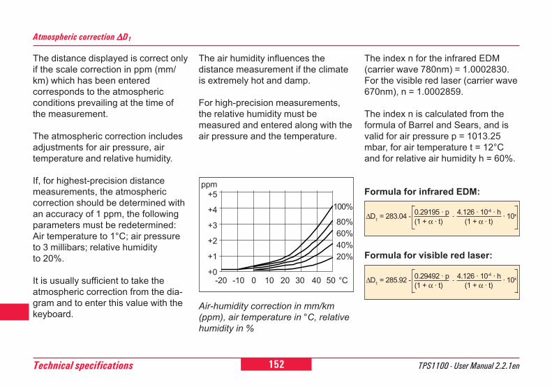
152 TPS1100 - User Manual 2.2.1enTechnical specifications
6
0
2
21
26
45
84
92
Atmospheric correction ∆∆∆∆∆D1
The distance displayed is correct onlyif the scale correction in ppm (mm/km) which has been enteredcorresponds to the atmosphericconditions prevailing at the time ofthe measurement.
The atmospheric correction includesadjustments for air pressure, airtemperature and relative humidity.
If, for highest-precision distancemeasurements, the atmosphericcorrection should be determined withan accuracy of 1 ppm, the followingparameters must be redetermined:Air temperature to 1°C; air pressureto 3 millibars; relative humidityto 20%.
It is usually sufficient to take theatmospheric correction from the dia-gram and to enter this value with thekeyboard.
The air humidity influences thedistance measurement if the climateis extremely hot and damp.
For high-precision measurements,the relative humidity must bemeasured and entered along with theair pressure and the temperature.
The index n for the infrared EDM(carrier wave 780nm) = 1.0002830.For the visible red laser (carrier wave670nm), n = 1.0002859.
The index n is calculated from theformula of Barrel and Sears, and isvalid for air pressure p = 1013.25mbar, for air temperature t = 12°Cand for relative air humidity h = 60%.
Formula for infrared EDM:
Air-humidity correction in mm/km(ppm), air temperature in °C, relativehumidity in %
∆D1 = 283.04 - 0.29195 · p(1 + α · t)
4.126 · 10-4 · h (1 + α · t)
· 10x
∆D1 = 285.92 - 0.29492 · p(1 + α · t)
4.126 · 10-4 · h (1 + α · t)
· 10x
Formula for visible red laser:
ppm+5
+4
+3
+2
+1
+0
100%
80%60%40%20%
-20 -10 0 10 20 30 40 50 °C
153TPS1100 - User Manual 2.2.1en Technical specifications
6
10
12
21
26
45
84
92
∆D1 = atmospheric correction [ppm]
p = air pressure [mbar]t = air temperature [°C]h = relative humidity [%]α = 1 / 273.16
x = 7.5 t237.3 + t + 0.7857
If the basic value of 60% relativehumidity as used by the EDM isretained, the maximum possible errorin the calculated atmosphericcorrection will be 2 ppm (2 mm / km).
Reduction to mean sea level ∆∆∆∆∆D2
The values for ∆D2 are always negati-ve and are derived from the followingformula:
∆D2 = reduction to mean sea level[ppm]
H = height of EDM above sealevel [m]
R = 6378 km
Projection distortion ∆∆∆∆∆D3
The magnitude of the projectiondistortion is in accordance with theprojection system used in a particularcountry, for which official tables aregenerally available. The followingformula is valid for cylindricalprojections such as that of Gauss-Krüger:
∆D3 = projection distortion [ppm]X = northing, distance from
projection zero line with thescale factor 1 [km]
R = 6378 km
In countries where the scale factor isnot unity, this formula cannot bedirectly applied.
∆D2 = - HR · 103
∆D3 = X2
2R2 · 106
Atmospheric correction ∆∆∆∆∆D1, continued
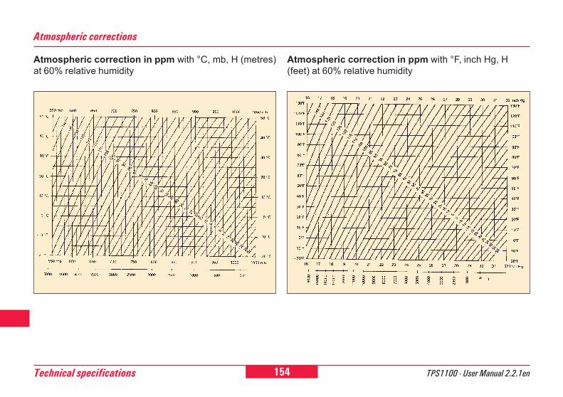
154 TPS1100 - User Manual 2.2.1enTechnical specifications
6
0
2
21
26
45
84
92
Atmospheric corrections
Atmospheric correction in ppm with °C, mb, H (metres)at 60% relative humidity
Atmospheric correction in ppm with °F, inch Hg, H(feet) at 60% relative humidity
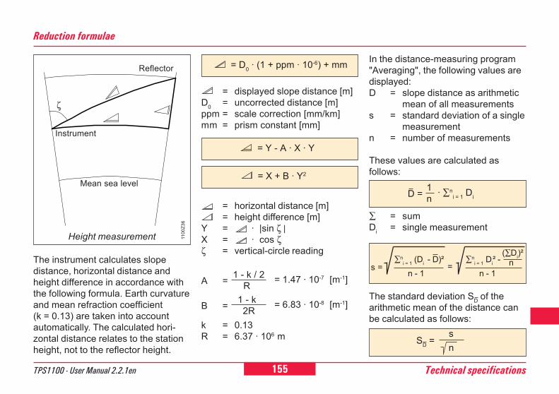
155TPS1100 - User Manual 2.2.1en Technical specifications
6
10
12
21
26
45
84
92
In the distance-measuring program"Averaging", the following values aredisplayed:D = slope distance as arithmetic
mean of all measurementss = standard deviation of a single
measurementn = number of measurements
These values are calculated asfollows:
Reduction formulae
= displayed slope distance [m]D0 = uncorrected distance [m]ppm = scale correction [mm/km]mm = prism constant [mm]
The instrument calculates slopedistance, horizontal distance andheight difference in accordance withthe following formula. Earth curvatureand mean refraction coefficient(k = 0.13) are taken into accountautomatically. The calculated hori-zontal distance relates to the stationheight, not to the reflector height.
∑ = sumDi = single measurement
The standard deviation SD of thearithmetic mean of the distance canbe calculated as follows:
= Y - A · X · Y
= X + B · Y2
s =∑n
i = 1 (Di - D)² n - 1
=∑n
i = 1 Di² - n - 1
(∑Di)² n
SD = s n
= horizontal distance [m]= height difference [m]
Y = · |sin ζ |X = · cos ζζ = vertical-circle reading
A = 1 - k / 2 R = 1.47 · 10-7 [m-1]
k = 0.13R = 6.37 · 106 m
B = 1 - k 2R = 6.83 · 10-8 [m-1]
Instrument
Reflector
Mean sea level
Height measurement
ζ
1100
Z36
= D0 · (1 + ppm · 10-6) + mm
D = 1n · ∑n
i = 1 Di
156Index TPS1100 - User Manual 2.2.1en
6
0
2
21
26
45
84
92
Index
A Absolute angle values ........................................... 88Accessories .......................................................... 94Activate/Deactivate Working Area(WORK+/WORK-) ................................................ 92Alpha mode .......................................................... 98Angle Dec. ............................................................ 99Angle Unit ............................................................. 99Atmospheric correction ......................................... 71Atmospheric correction DD1 ............................... 154ATR collimation ..................................................... 41ATR mode ............................................................. 15ATR-Mode (ATR+ / ATR-) ..................................... 86Auto Dist ............................................................. 105Autoexec ............................................................... 99Automatic Reflector Search .................................. 89Automatic Target Recognition ............................... 85
Battery ................................................................ 147
C Care and transport .............................................. 119CAUTION ............................................................... 4Changing face (I<>II) ............................................ 75Charging the battery ............................................. 23Check Orientation ................................................. 82Checking and adjusting ........................................ 29Codelist ........................................................ 50, 107
Coding .................................................................. 79Communication ..................................................... 83Compens.Index Error ........................................... 32Compensator ............................................... 32, 101Configuration file (LOAD) ..................................... 95Configuration parameters ..................................... 99Contents ................................................................. 6Converting data .................................................... 56Coord. Seq. ........................................................ 100Copying a codelist (COPY) ................................... 51Creating a new codelist (NEW) ............................ 51Creating a new job (NEW) .................................... 50
D DANGER ................................................................ 4Data configuration ................................................ 49Data flow ............................................................... 19Data format ......................................................... 108Data Job ............................................................. 107Data job (D JOB) .................................................. 49Data management ................................................ 51Date ...................................................................... 98Date form. ............................................................. 98Decimal places ..................................................... 99Define Limits ......................................................... 94Definition of a Working Area (WORKA) ................ 91Deleting the GSI block (Del B) .............................. 76Description of the system ..................................... 12
B
157TPS1100 - User Manual 2.2.1en Index
6
10
12
21
26
45
84
92
Index, contd.Display mask ........................................................ 61Displaying and editing GSI data (SEARC) ............ 54Displaying and importing point data (VIEW) ......... 54Dist. Dec. .............................................................. 99Dist. Delay .......................................................... 103Dist. Unit ............................................................... 99Distance corrections, ppm .................................... 71Distance measurement ......................................... 67
E EDM measuring program ..................................... 68EDM test ............................................................... 71Electronic bubble .................................................. 28Electronic bubble (LEVEL) .................................... 92External power supply .......................................... 25
F Face I .................................................................. 100Formatting the PC-card (FORMT) ........................ 59
G General parameters .............................................. 97GeoBasic .............................................................. 19Geometrical correction ......................................... 72GSI communication parameters ........................... 83GSI-parameters .................................................... 62
H Hz / V .................................................................... 88Hz system ........................................................... 100Hz-collim. Error ..................................................... 37Hz-Corr. .............................................................. 101
I Illumination ........................................................... 93Importing point data (IMPOR) ............................... 53Increment ............................................................ 106Incrementation of point numbers ........................ 106Individual point number (INDIV / RUN) ................. 79Info / Atrib ........................................................... 104Inserting / replacing battery .................................. 24Inspecting the PC-card (PROOF) ......................... 60Instrument designation and softwareversion (INFO) ....................................................... 92Interface parameters (GeoCOM) .......................... 83Introduction ........................................................... 10
K Key beep............................................................... 98
L L.UNT-Mode (L.INT+ / L.GO) ............................... 87Language .............................................................. 99LAST mode (LAST) .............................................. 88Last point number (L.Pt.) ...................................... 76
158Index TPS1100 - User Manual 2.2.1en
6
0
2
21
26
45
84
92
Index, contd.Line of sight .......................................................... 36Load application .................................................... 97Load system language.......................................... 97Loading a configuration file (LOAD) ...................... 95Loading a system-parameter file .......................... 96LOCK mode .......................................................... 15LOCK-Mode (LOCK+ / LOCK-) ............................ 86
M Manual distance entry ........................................... 76Manual input of coordinates (INPUT) ................... 56Meas Job ............................................................ 107Meas. job (M JOB) ................................................ 49Measurement & recording (REC) ......................... 73Measurement functions ........................................ 66Measurement parameters .................................. 105Measuring distances and angles separately(DIST + REC) ....................................................... 74Measuring distances and angles together withstorage (ALL) ........................................................ 75Mini prism + holder ............................................... 22
O Offs. Mode .......................................................... 105Offset .................................................................... 78On-line mode ........................................................ 84
P Placeholder (wild cards) in searching for points ... 55Point coding ................................................... 80, 81Positioning the last point stored (LAST) ............... 77Power mode ....................................................... 103PowerSearch .......................... 12, 15, 90, 136, 150Power Time......................................................... 103PPM Corrections .................................................. 72PPM entry ........................................................... 104Preparation ........................................................... 22Press. Unit .......................................................... 100Product identification .............................................. 3Projection distortion DD3 .................................... 151Pt. Id. mode ........................................................ 105
Q Quick Coding (QCod+ / QCod-) ........................... 81Quick-Code......................................................... 107
R RCS communication parameters .......................... 84RCS Searching Window ....................................... 90Recording mask............................................. 60, 61Reduced distance corrections ppm ...................... 73Reduction to mean sea level ∆D2....................... 153Reflector ............................................................... 68Refraction correction ............................................ 73Relative angle values ............................................ 88Release V-angle ................................................. 102
159TPS1100 - User Manual 2.2.1en Index
6
10
12
21
26
45
84
92
Index, contd.
S Safety directions ................................................. 121Scale correction (ppm) ....................................... 151Sect. Angle ......................................................... 102Sect. Beep .......................................................... 102Setting / defining prisms ................................ 70, 71Setting and entering the Hz direction (SetHz) ....... 67Setting the display mask (DMask) ........................ 61Setting the redording mask(RMask) .............. 60, 61Setting up the instrument ...................................... 27Short instructions .................................................. 22Standard coding ............................................. 79, 80Station setup ......................................................... 66Storage concept ................................................... 19Storing station data (REC) .................................... 75Switch between Fast measurement/Rapid Tracking ..................................................... 70Switch between IR/RL .......................................... 69Switch between Standard/Tracking ...................... 70Switching between display masks (>DISP) .......... 78Symbols used in this manual .................................. 4System functions .................................................. 49System parameters .............................................. 97System-parameter file .......................................... 96
T Target type ............................................................ 68Technical specifications ...................................... 143Temp. Unit .......................................................... 100Tilting axis ............................................................. 38Time ...................................................................... 98Time form. ............................................................ 98
V V-angle modes ..................................................... 77V-Display ............................................................ 103V-index error ......................................................... 34View of chapters ..................................................... 5
W WARNING .............................................................. 4Work settings ...................................................... 107

Leica Geosystems AGCH-9435 Heerbrugg
(Switzerland)Phone +41 71 727 31 31Fax +41 71 727 46 73
www.leica-geosystems.com
Printed in Switzerland - Copyright LeicaGeosystems AG, Heerbrugg, Switzerland 2003Translation of original text (710476-2.2.1de)
710477-2.2.1en
Leica Geosystems AG, Heerbrugg,Switzerland has been certified as beingequipped with a quality system which meetsthe International Standards of QualityManagement and Quality Systems (ISOstandard 9001) and Environmental Manage-ment Systems (ISO standard 14001).
Total Quality Management -Our commitment to total customersatisfaction
Ask your local Leica Geosystems agent for moreinformation about our TQM program.