Embed Size (px)
Citation preview
Leica Stereo-Fluorescence SystemsUser Manual

3
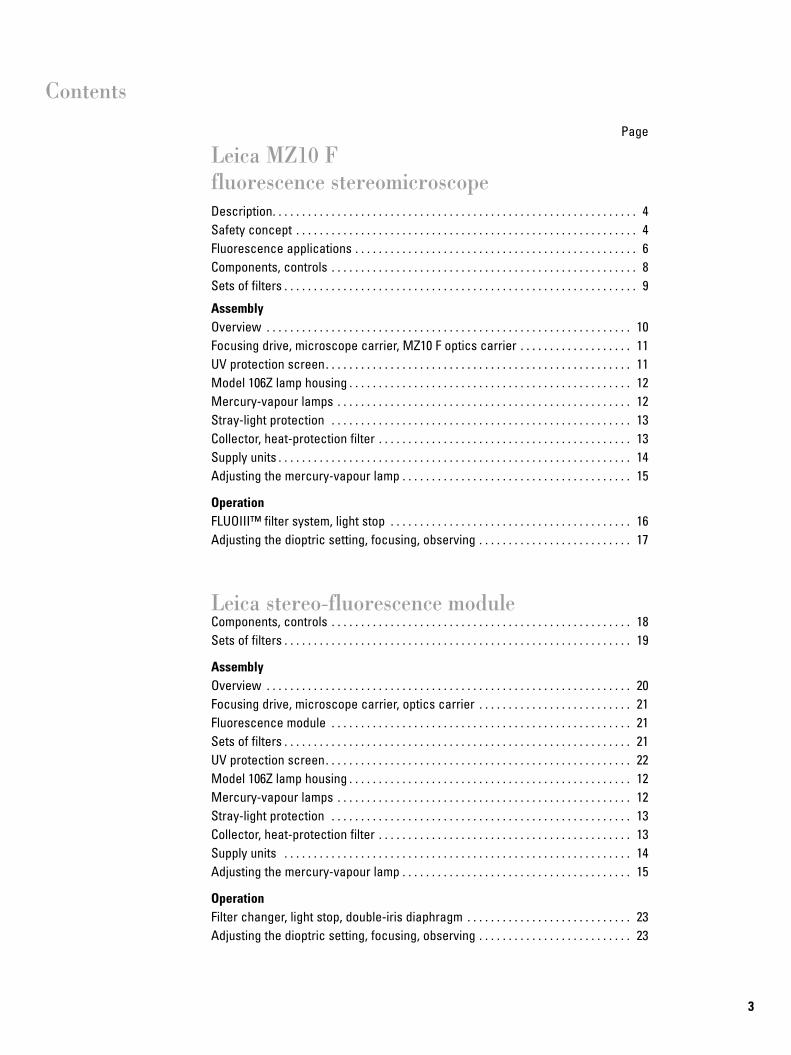
Contents
Page
Leica MZ10 F fluorescence stereomicroscopeDescription . . . . . . . . . . . . . . . . . . . . . . . . . . . . . . . . . . . . . . . . . . . . . . . . . . . . . . . . . . . . . . 4Safety concept . . . . . . . . . . . . . . . . . . . . . . . . . . . . . . . . . . . . . . . . . . . . . . . . . . . . . . . . . . 4Fluorescence applications . . . . . . . . . . . . . . . . . . . . . . . . . . . . . . . . . . . . . . . . . . . . . . . . 6Components, controls . . . . . . . . . . . . . . . . . . . . . . . . . . . . . . . . . . . . . . . . . . . . . . . . . . . . 8Sets of filters . . . . . . . . . . . . . . . . . . . . . . . . . . . . . . . . . . . . . . . . . . . . . . . . . . . . . . . . . . . . 9
AssemblyOverview . . . . . . . . . . . . . . . . . . . . . . . . . . . . . . . . . . . . . . . . . . . . . . . . . . . . . . . . . . . . . . 10Focusing drive, microscope carrier, MZ10 F optics carrier . . . . . . . . . . . . . . . . . . . 11UV protection screen . . . . . . . . . . . . . . . . . . . . . . . . . . . . . . . . . . . . . . . . . . . . . . . . . . . . 11Model 106Z lamp housing . . . . . . . . . . . . . . . . . . . . . . . . . . . . . . . . . . . . . . . . . . . . . . . . 12Mercury-vapour lamps . . . . . . . . . . . . . . . . . . . . . . . . . . . . . . . . . . . . . . . . . . . . . . . . . . 12Stray-light protection . . . . . . . . . . . . . . . . . . . . . . . . . . . . . . . . . . . . . . . . . . . . . . . . . . . 13Collector, heat-protection filter . . . . . . . . . . . . . . . . . . . . . . . . . . . . . . . . . . . . . . . . . . . 13Supply units . . . . . . . . . . . . . . . . . . . . . . . . . . . . . . . . . . . . . . . . . . . . . . . . . . . . . . . . . . . . 14Adjusting the mercury-vapour lamp . . . . . . . . . . . . . . . . . . . . . . . . . . . . . . . . . . . . . . . 15
OperationFLUOIII™ filter system, light stop . . . . . . . . . . . . . . . . . . . . . . . . . . . . . . . . . . . . . . . . . 16Adjusting the dioptric setting, focusing, observing . . . . . . . . . . . . . . . . . . . . . . . . . . 17
Leica stereo-fluorescence moduleComponents, controls . . . . . . . . . . . . . . . . . . . . . . . . . . . . . . . . . . . . . . . . . . . . . . . . . . . 18Sets of filters . . . . . . . . . . . . . . . . . . . . . . . . . . . . . . . . . . . . . . . . . . . . . . . . . . . . . . . . . . . 19
AssemblyOverview . . . . . . . . . . . . . . . . . . . . . . . . . . . . . . . . . . . . . . . . . . . . . . . . . . . . . . . . . . . . . . 20Focusing drive, microscope carrier, optics carrier . . . . . . . . . . . . . . . . . . . . . . . . . . 21Fluorescence module . . . . . . . . . . . . . . . . . . . . . . . . . . . . . . . . . . . . . . . . . . . . . . . . . . . 21Sets of filters . . . . . . . . . . . . . . . . . . . . . . . . . . . . . . . . . . . . . . . . . . . . . . . . . . . . . . . . . . . 21UV protection screen . . . . . . . . . . . . . . . . . . . . . . . . . . . . . . . . . . . . . . . . . . . . . . . . . . . . 22Model 106Z lamp housing . . . . . . . . . . . . . . . . . . . . . . . . . . . . . . . . . . . . . . . . . . . . . . . . 12Mercury-vapour lamps . . . . . . . . . . . . . . . . . . . . . . . . . . . . . . . . . . . . . . . . . . . . . . . . . . 12Stray-light protection . . . . . . . . . . . . . . . . . . . . . . . . . . . . . . . . . . . . . . . . . . . . . . . . . . . 13Collector, heat-protection filter . . . . . . . . . . . . . . . . . . . . . . . . . . . . . . . . . . . . . . . . . . . 13Supply units . . . . . . . . . . . . . . . . . . . . . . . . . . . . . . . . . . . . . . . . . . . . . . . . . . . . . . . . . . . 14Adjusting the mercury-vapour lamp . . . . . . . . . . . . . . . . . . . . . . . . . . . . . . . . . . . . . . . 15
OperationFilter changer, light stop, double-iris diaphragm . . . . . . . . . . . . . . . . . . . . . . . . . . . . 23Adjusting the dioptric setting, focusing, observing . . . . . . . . . . . . . . . . . . . . . . . . . . 23
4
Description
Fluorescence techniqueSome substances fluoresce when irradiated with short-wave light . This property is utilized in the fluorescence technique, in which certain structures and features which do not fluo-rescence can be tagged with a fluorescing dye . An example is green-fluorescing protein (GFP), which is used in molecular biology .
Stereo-fluorescenceWith Leica fluorescence systems you can complete unprepared fluorescing specimens to be non-destructively studied in three dimensions, mani pulated, sorted and recorded . The intense light emitted by the mercury-vapour burner, used in conjunction with selected filter sets, enables even the finest structures to be differentiated and expands the amount of information revealed by the incident-light fluorescence technique .
Fluorescence stereomicroscopeThe Leica MZ10 F with 10:1 zoom is the routine stereo-microscope for fluorescence applications . The patented sepa-rate beam path (TriBeam™) for the fluorescence illuminator and the patented filter system (FLUOIII™) together produce excellent fluorescence images .
Stereo-fluorescence moduleThe stereo-fluorescence modul can be combined with the Leica stereomicroscope models MS5, MZ6, MZ7 .5, MZ9 .5, MZ12 .5, MZ16, and with older models .
User manualThe present user manual describes only the functions of the fluorescence illuminator, the use of the filter sets, and the fitting of the fluorescence module . For detailed information about the use of the stereomicroscope, its care and its safety, please refer to those sections of the separate manual M2-105-0EN which relate to the Leica MZ12 .5 with 12 .5:1 zoom .
Safety conceptBefore you set up the instrument and before you fit the fluorescence illuminator, read:• thisusermanual,observingthenotesrelatingtosafety
• theusermanualforyourstereomicroscope,observingthenotes relating to safety and care .
Permitted usesLeica stereo-fluorescence systems are equipped with a special fluorescence illuminator . They are intended for the three- dimensional observation of fluorescing objects . They consist of:– a stereomicroscope with stand, binocular tube and
eyepieces
– an integrated FLUOIII filter system (for MZ10 F) or a separate stereo-fluorescence module
– appropriate filter sets with barrier- and excitation filters, a light stop, and individually-selectable filters
– a UV protection screen
– a lamp housing with high-pressure mercury vapour burner
– a supply unit with power cable .
Prohibited usesThe use of Leica stereo-fluorescence systems in a different manner from that described in this user manual can lead to inju-ry, malfunction and damage .– Do not fit different plugs or cables
– Do not dismantle or modify components unless instructions for doing so are given in the user manual
– Components may only be opened by authorized personnel .
Place of useLeica stereo-fluorescence systems are intended for use in closed rooms and may not be used outdoors .
Responsibilities of person in charge of instrument– Ensure that the Leica stereo-fluorescence systems are
operated, maintained and repaired only by authorized and trained personnel
– Ensure that personnel who use the instrument have read and understood this user manual and in particular all safety instructions .
5
Servicing and repairs– Repairs may only be carried out by Leica-trained service
technicians or by technical personnel authorized to do so by the person in charge of the instrument
– Only original Leica spare parts may be used
– Unplug the power cable before opening the supply unit . Touching live circuits can cause injury .
Legal requirementsAdhere to general and local regulations relating to accident prevention and environmental protection .
Conformity with European Community directive Leica stereo-fluorescence systems and their accessories are constructed in accordance with the latest technologies and are provided with a statement of conformity with EC requirements .
Light source: Safety regulations
Safety measures introduced by manufacturer– UV protection screen in front of the specimen plane prevents
direct UV radiation from reaching the eyes .
– Dummy filter carriers in the unoccupied positions of the rapid filter changer prevent direct UV radiation from reaching the eyes
– UV filters in the observation beam paths protect the eyes against UV radiation .
– Stray-light protection on the underside of the lamp housing protects the user's hands against UV radiation .
WarningUV can damage your eyes . Therefore:– Never look at the light spot on the specimen plane without
the UV protection screen in position
– Never look into the eyepieces unless there is an excitation filter in the beam path
– Always keep dummy filter carriers in the unoccupied positions of the rapid filter changer (for MZ10 F)
– Do not place the specimen on a white or highly-reflective background .
Supply unit• Pull the power plug of the supply unit out from the power sok-
ket:
– when assembling and dismantling the lamp housing
– before opening the lamp housing
– when changing the mercury-vapour burner and other components such as the heat- protection filter or the collector
– when servicing the supply unit
Lamp housing• Never open the lamp housing while the burner is switched on
(risk of explosion, UV irradiation, dazzling)
• Always allow the lamp housing to cool for at least 15 minutes before opening it (risk of burner exploding)
• Never cover the ventilator slots on the lamp housing (risk of fire)
Mercury-vapour lamp• Read the user manual and safety directions provided by the
manufacturer of the mercury-vapour burner, and particularly those relating to its breakage and to the release of mercury
• Before transporting the equipment, remove the mercury-vapour burner and place it in its original packaging . Use the transport peg in place of the burner, to secure movable parts within the lamp housing
• When the mercury-vapour burner has reached the end of its nominal working life as indicated by the manufacturer’s information and the time counter on the supply unit, change the discoloured burner (increased risk of explosion)
• Leica declines all responsibility for injury and damage resulting from exploding, incorrectly-fitted or incorrectly-used mercury- vapour burners .
6
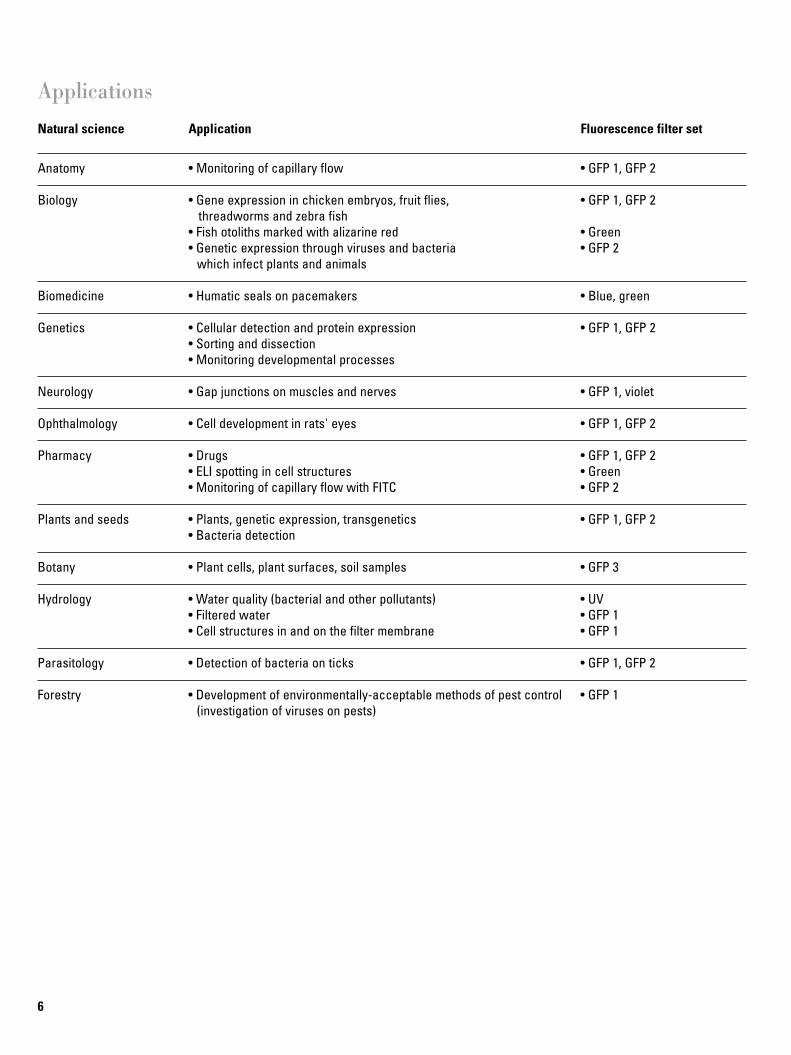
ApplicationsNatural science Application Fluorescence filter set
Anatomy •Monitoringofcapillaryflow •GFP1,GFP2
Biology •Geneexpressioninchickenembryos,fruitflies, •GFP1,GFP2 threadworms and zebra fish •Fishotolithsmarkedwithalizarinered •Green •Geneticexpressionthroughvirusesandbacteria •GFP2 which infect plants and animals
Biomedicine •Humaticsealsonpacemakers •Blue,green
Genetics •Cellulardetectionandproteinexpression •GFP1,GFP2 •Sortinganddissection •Monitoringdevelopmentalprocesses
Neurology •Gapjunctionsonmusclesandnerves •GFP1,violet
Ophthalmology •Celldevelopmentinrats'eyes •GFP1,GFP2
Pharmacy •Drugs •GFP1,GFP2 •ELIspottingincellstructures •Green •MonitoringofcapillaryflowwithFITC •GFP2
Plantsandseeds •Plants,geneticexpression,transgenetics •GFP1,GFP2 •Bacteriadetection
Botany •Plantcells,plantsurfaces,soilsamples •GFP3
Hydrology •Waterquality(bacterialandotherpollutants) •UV •Filteredwater •GFP1 •Cellstructuresinandonthefiltermembrane •GFP1
Parasitology •Detectionofbacteriaonticks •GFP1,GFP2
Forestry •Developmentofenvironmentally-acceptablemethodsofpestcontrol •GFP1 (investigation of viruses on pests)
7
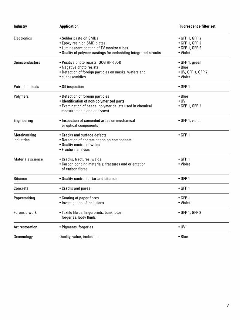
Industry Application Fluorescence filter set
Electronics •SolderpasteonSMDs •GFP1,GFP2 •EpoxyresinonSMDplates •GFP1,GFP2 •LuminescentcoatingofTVmonitortubes •GFP1,GFP2 •Qualityofpolymercastingsforembeddingintegratedcircuits •Violet
Semiconductors •Positivephotoresists(OCGHPR504) •GFP1,green •Negativephotoresists •Blue •Detectionofforeignparticlesonmasks,wafersand •UV,GFP1,GFP2 •subassemblies •Violet
Petrochemicals •Oilinspection •GFP1
Polymers •Detectionofforeignparticles •Blue •Identificationofnon-polymerizedparts •UV •Examinationofbeads(polymerpelletsusedinchemical •GFP1,GFP2 measurements and analyses)
Engineering •Inspectionofcementedareasonmechanical •GFP1,violet or optical components
Metalworking •Cracksandsurfacedefects •GFP1industries •Detectionofcontaminationoncomponents •Qualitycontrolofwelds •Fractureanalysis
Materialsscience •Cracks,fractures,welds •GFP1 •Carbonbondingmaterials;fracturesandorientation •Violet
of carbon fibres
Bitumen •Qualitycontrolfortarandbitumen •GFP1
Concrete •Cracksandpores •GFP1
Papermaking •Coatingofpaperfibres •GFP1 •Investigationofinclusions •Violet
Forensicwork •Textilefibres,fingerprints,banknotes, •GFP1,GFP2 forgeries, body fluids
Artrestoration •Pigments,forgeries •UV
Gemmology Quality,value,inclusions •Blue
8
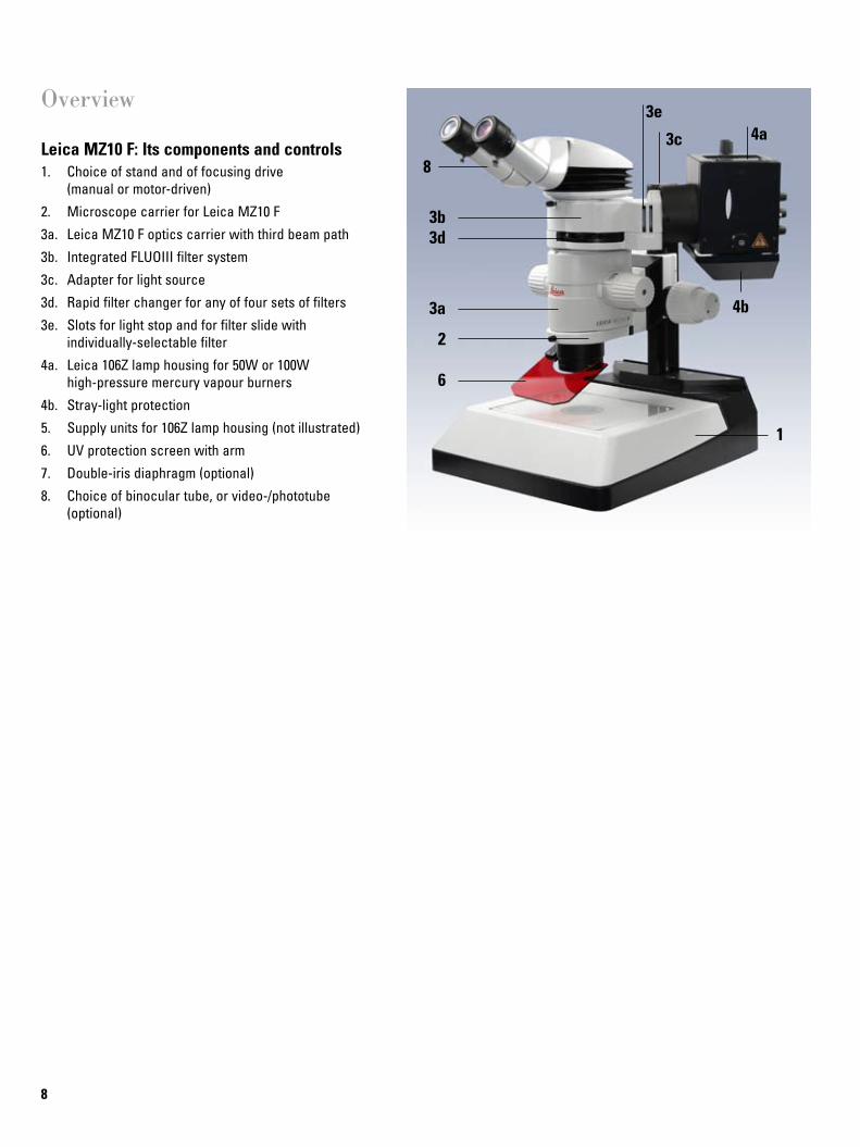
Overview
Leica MZ10 F: Its components and controls1 . Choice of stand and of focusing drive
(manual or motor-driven)
2 . Microscope carrier for Leica MZ10 F
3a . Leica MZ10 F optics carrier with third beam path
3b . Integrated FLUOIII filter system
3c . Adapter for light source
3d . Rapid filter changer for any of four sets of filters
3e . Slots for light stop and for filter slide with individually-selectable filter
4a . Leica 106Z lamp housing for 50W or 100W high-pressure mercury vapour burners
4b . Stray-light protection
5 . Supply units for 106Z lamp housing (not illustrated)
6 . UV protection screen with arm
7 . Double-iris diaphragm (optional)
8 . Choice of binocular tube, or video-/phototube (optional)
1
2
4b
4a3e
3c
8
3b
3a
6
3d
9
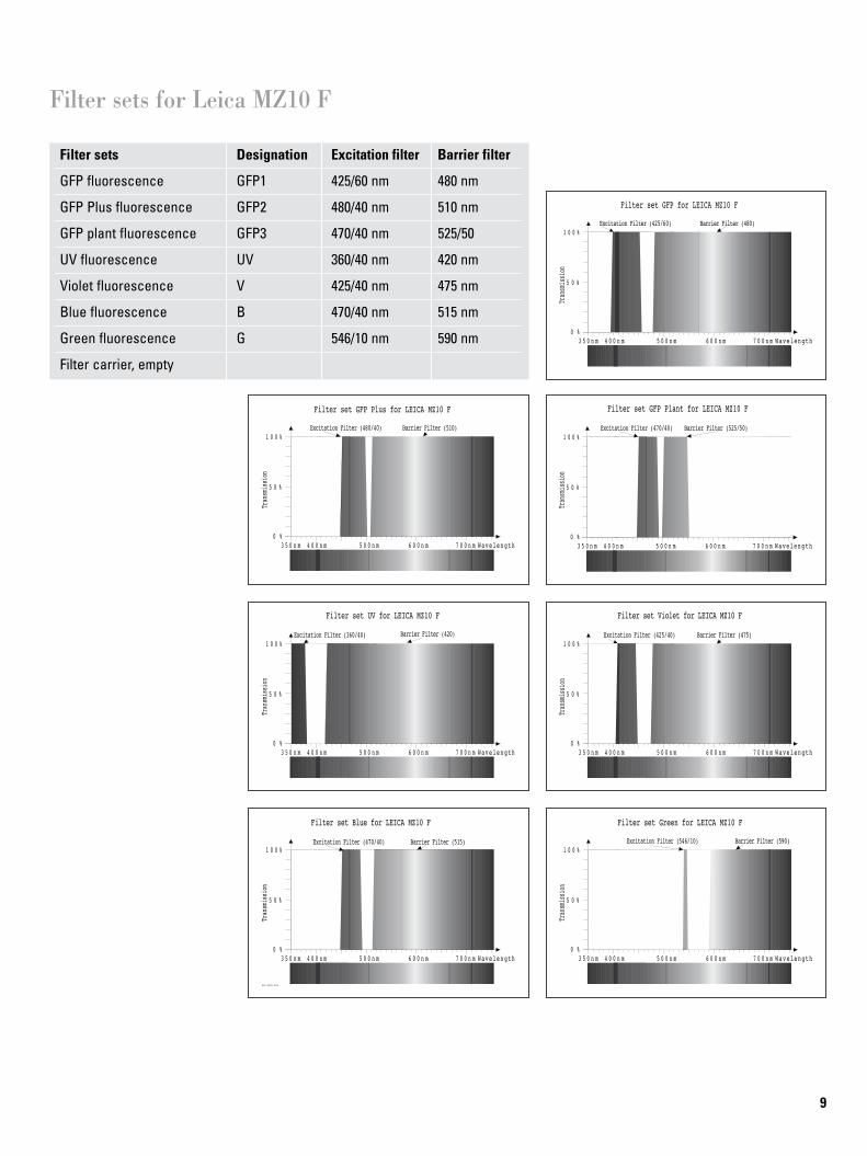
Filter sets Designation Excitation filter Barrier filter
GFP fluorescence GFP1 425/60 nm 480 nm
GFP Plus fluorescence GFP2 480/40 nm 510 nm
GFP plant fluorescence GFP3 470/40 nm 525/50
UV fluorescence UV 360/40 nm 420 nm
Violet fluorescence V 425/40 nm 475 nm
Blue fluorescence B 470/40 nm 515 nm
Green fluorescence G 546/10 nm 590 nm
Filter carrier, empty
Filter sets for Leica MZ10 F
1 0 0 %
5 0 %
0 %4 0 0 n m 5 0 0 n m 6 0 0 n m 7 0 0 n m Wavelength
Filter set GFP Plus for LEICA MZ10 F
3 5 0 n m
Excitation Filter (480/40) Barrier Filter (510)
Tran
smis
sion
1 0 0 %
5 0 %
0 %4 0 0 n m 5 0 0 n m 6 0 0 n m 7 0 0 n m Wavelength
Filter set UV for LEICA MZ10 F
3 5 0 n m
Excitation Filter (360/40) Barrier Filter (420)
Tran
smis
sion
1 0 0 %
5 0 %
0 %4 0 0 n m 5 0 0 n m 6 0 0 n m 7 0 0 n m Wavelength
Filter set Blue for LEICA MZ10 F
BL U - S P E K . D R W
3 5 0 n m
Barrier Filter (515)Excitation Filter (470/40)
Tran
smis
sion
1 0 0 %
5 0 %
0 %4 0 0 n m 5 0 0 n m 6 0 0 n m 7 0 0 n m Wavelength
Filter set GFP Plant for LEICA MZ10 F
3 5 0 n m
Excitation Filter (470/40) Barrier Filter (525/50)
Tran
smis
sion
1 0 0 %
5 0 %
0 %4 0 0 n m 5 0 0 n m 6 0 0 n m 7 0 0 n m Wavelength
Filter set GFP for LEICA MZ10 F
3 5 0 n m
Excitation Filter (425/60) Barrier Filter (480)
Tran
smis
sion
Tran
smis
sion
1 0 0 %
5 0 %
0 %4 0 0 n m 5 0 0 n m 6 0 0 n m 7 0 0 n m Wavelength
Filter set Violet for LEICA MZ10 F
3 5 0 n m
Excitation Filter (425/40) Barrier Filter (475)
1 0 0 %
5 0 %
0 %4 0 0 n m 5 0 0 n m 6 0 0 n m 7 0 0 n m Wavelength
Filter set Green for LEICA MZ10 F
3 5 0 n m
Excitation Filter (546/10) Barrier Filter (590)
Tran
smis
sion
10
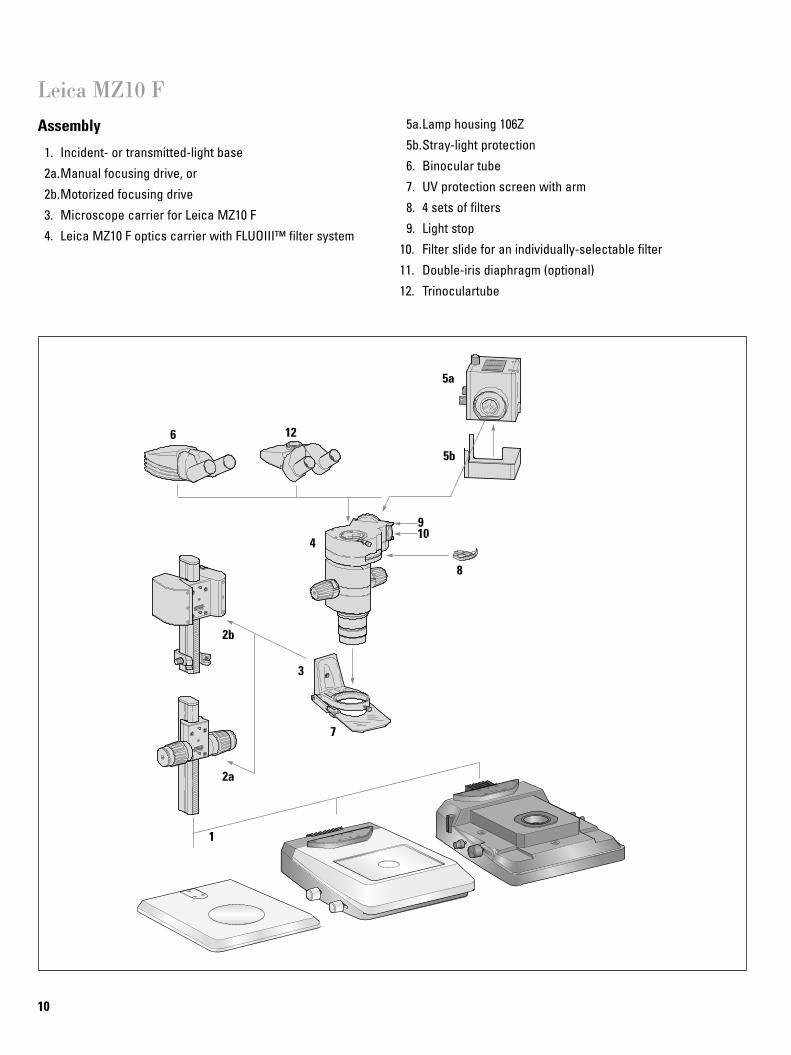
Leica MZ10 FAssembly
1 . Incident- or transmitted-light base
2a . Manual focusing drive, or
2b . Motorized focusing drive
3 . Microscope carrier for Leica MZ10 F
4 . Leica MZ10 F optics carrier with FLUOIII™ filter system
5a . Lamp housing 106Z
5b . Stray-light protection
6 . Binocular tube
7 . UV protection screen with arm
8 . 4 sets of filters
9 . Light stop
10 . Filter slide for an individually-selectable filter
11 . Double-iris diaphragm (optional)
12 . Trinoculartube
4
5a
2a
8
1
3
6
7
2b
910
12
5b
11
Leica MZ10 F
Focusing drive ➜ base of stand
▶ Connect manually-operated or motor-driven focusing drive, complete with column, to base, as described in user manual M2-105-0EN .
Before using the motor focus, you must read the safety directions in the accompanying user manual M2-267-104.
Microscope carrier ➜ focusing drive
▶ Fit microscope carrier of Leica MZ10 F to focusing drive in accordance with user manual M2-105-0EN .
Optics carrier ➜ microscope carrier
The Leica MZ10 F optics carrier and the FLUOIII filter system form a single unit which was factory-adjusted . Do not try to dismantle it .
▶ Fit the Leica MZ10 F optics carrier to the microscope carrier in accordance with the user manual M2-105-0EN .
Additional components
▶ Fit the remaining components, such as binocular tube, eyepi-eces and optional double-iris diaphragm, to the FLUOIII filter system in accordance with user manual M2-105-0EN .
Video-/phototube
To permit shorter exposure times in fluorescence photography, werecommendyoutousethevideo-/phototubeHDVwith100%light in the video-/photo beam path .
Double-iris diaphragm
The double-iris diaphragm is used to increase the depth of field (see user manual M2-105-0EN) .
▶ Fit the double-iris diaphragm to the FLUOIII filter system .
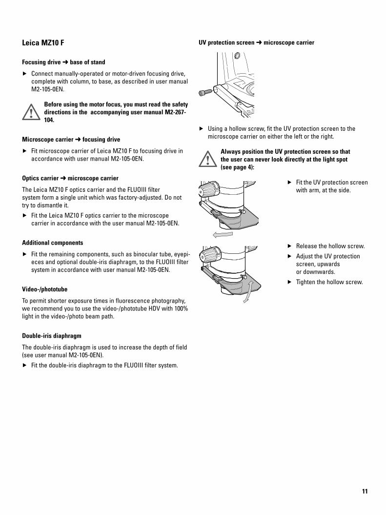
UV protection screen ➜ microscope carrier
▶ Using a hollow screw, fit the UV protection screen to the microscope carrier on either the left or the right .
Always position the UV protection screen so that the user can never look directly at the light spot (see page 4):
▶ Fit the UV protection screen with arm, at the side .
▶ Release the hollow screw .
▶ Adjust the UV protection screen, upwards or downwards .
▶ Tighten the hollow screw .
12
Assembly
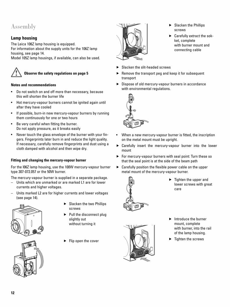
Lamp housingThe Leica 106Z lamp housing is equipped .For information about the supply units for the 106Z lamp housing, see page 14 .Model 105Z lamp housings, if available, can also be used .
Observe the safety regulations on page 5
Notes and recommendations
• Donotswitchonandoffmorethannecessary,because this will shorten the burner life
• Hotmercury-vapourburnerscannotbeignitedagainuntilafter they have cooled
• Ifpossible,burn-innewmercury-vapourburnersbyrunningthem con tinuously for one or two hours
• Beverycarefulwhenfittingtheburner. Do not apply pressure, as it breaks easily
• Nevertouchtheglassenvelopeoftheburnerwithyourfin-gers . Fingerprints later burn in and reduce the light quality . If necessary, carefully remove fingerprints and dust using a cloth damped with alcohol and then wipe dry .
Fitting and changing the mercury-vapour burner
For the l06Z lamp housing, use the 100W mercury-vapour burner type 307-072 .057 or the 50W burner .
The mercury-vapour burner is supplied in a separate package . – Units which are unmarked or are marked L1 are for lower
currents and higher voltages .
– Units marked L2 are for higher currents and lower voltages (see page 14) .
▶ Slacken the two Phillips screws
▶ Pull the disconnect plug slightly out without turning it
▶ Flip open the cover
▶ Slacken the Phillips screws
▶ Carefully extract the sok-ket, complete with burner mount and connecting cable
▶ Slacken the slit-headed screws
▶ Remove the transport peg and keep it for subsequent transport
▶ Dispose of old mercury-vapour burners in accordance with environmental regulations .
• Whenanewmercury-vapourburnerisfitted,theinscriptionon the metal mount must be upright .
▶ Carefully insert the mercury-vapour burner into the lower mount
▶ For mercury-vapour burners with seal point: Turn these so that the seal point is at the side of the beam path
▶ Carefully position the flexible power cable on the upper metal mount of the mercury-vapour burner .
▶ Tighten the upper and lower screws with great care
▶ Introduce the burner mount, complete with burner, into the rail of the lamp housing .
▶ Tighten the screws
13
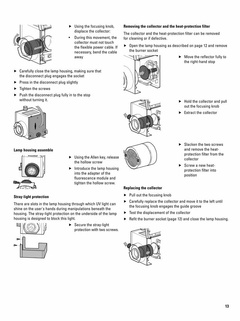
▶ Using the focusing knob, displace the collector:
• Duringthismovement,thecollector must not touch the flexible power cable . If necessary, bend the cable away
▶ Carefully close the lamp housing, making sure that the dis connect plug engages the socket
▶ Press in the disconnect plug slightly
▶ Tighten the screws
▶ Push the disconnect plug fully in to the stop without turning it .
Lamp housing assemble
▶ Using the Allen key, release the hollow screw
▶ Introduce the lamp housing into the adapter of the fluo res cence module and tighten the hollow screw .
Stray-light protection
There are slots in the lamp housing through which UV light can shine on the user's hands during manipulations beneath the housing . The stray-light protection on the underside of the lamp housing is designed to block this light .
▶ Secure the stray-light protection with two screws .
Removing the collector and the heat-protection filter
The collector and the heat-protection filter can be removed for cleaning or if defective .
▶ Open the lamp housing as described on page 12 and remove the burner socket
▶ Move the reflector fully to the right-hand stop
▶ Holdthecollectorandpullout the focusing knob
▶ Extract the collector
▶ Slacken the two screws and remove the heat- protection filter from the collector
▶ Screw a new heat- pro tection filter into position
Replacing the collector
▶ Pull out the focusing knob
▶ Carefully replace the collector and move it to the left until the focusing knob engages the guide groove
▶ Test the displacement of the collector
▶ Refit the burner socket (page 12) and close the lamp housing .
14
Assembly
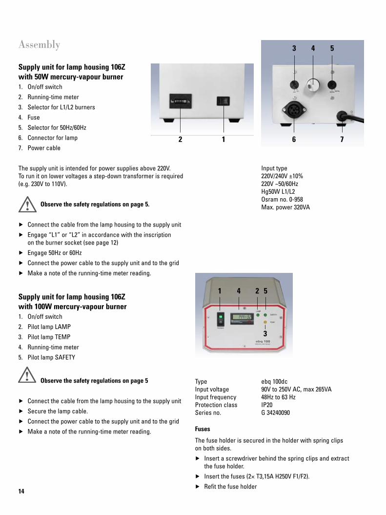
Supply unit for lamp housing 106Z with 50W mercury-vapour burner1 . On/off switch
2 . Running-time meter
3 . Selector for L1/L2 burners
4 . Fuse
5. Selectorfor50Hz/60Hz
6 . Connector for lamp
7 . Power cable
The supply unit is intended for power supplies above 220V . To run it on lower voltages a step-down transformer is required (e .g . 230V to 110V) .
Observe the safety regulations on page 5.
▶ Connect the cable from the lamp housing to the supply unit
▶ Engage “L1” or “L2” in accordance with the inscription on the burner socket (see page 12)
▶ Engage50Hzor60Hz
▶ Connect the power cable to the supply unit and to the grid
▶ Make a note of the running-time meter reading .
Supply unit for lamp housing 106Z with 100W mercury-vapour burner1 . On/off switch
2 . Pilot lamp LAMP
3 . Pilot lamp TEMP
4 . Running-time meter
5 . Pilot lamp SAFETY
Observe the safety regulations on page 5
▶ Connect the cable from the lamp housing to the supply unit
▶ Secure the lamp cable .
▶ Connect the power cable to the supply unit and to the grid
▶ Make a note of the running-time meter reading .
2 1 6 7
543
Input type220V/240V±10%220V~50/60HzHg50WL1/L2Osram no . 0-958Max . power 320VA
Type ebq 100dcInput voltage 90V to 250V AC, max 265VAInputfrequency 48Hzto63HzProtection class IP20Series no . G 34240090
Fuses
The fuse holder is secured in the holder with spring clips on both sides .
▶ Insert a screwdriver behind the spring clips and extract the fuse holder .
▶ Insert the fuses (2×T3,15AH250VF1/F2).
▶ Refit the fuse holder
1
3
24 5
15
3
1
2
456
Hg50W Hg100W
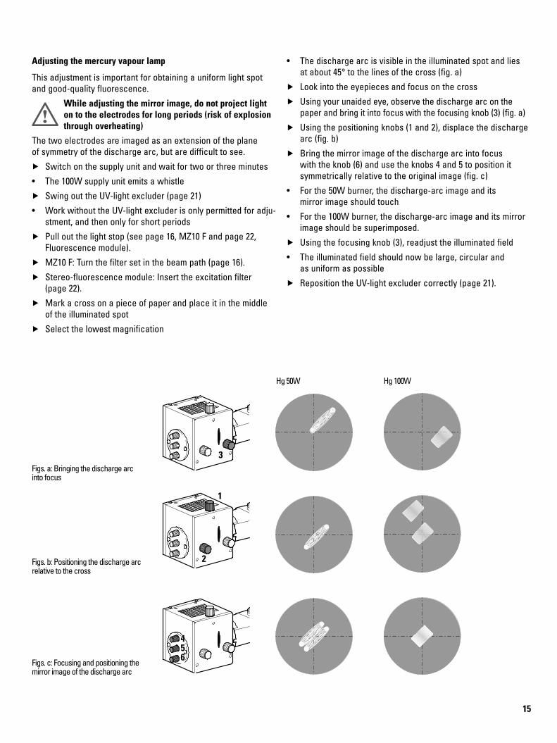
Adjusting the mercury vapour lamp
This adjustment is important for obtaining a uniform light spot and good-quality fluorescence .
While adjusting the mirror image, do not project light on to the electrodes for long periods (risk of explosion through overheating)
The two electrodes are imaged as an extension of the plane of symmetry of the discharge arc, but are difficult to see .
▶ Switch on the supply unit and wait for two or three minutes
• The100Wsupplyunitemitsawhistle
▶ Swing out the UV-light excluder (page 21)
• WorkwithouttheUV-lightexcluderisonlypermittedforadju-stment, and then only for short periods
▶ Pull out the light stop (see page 16, MZ10 F and page 22, Fluorescence module) .
▶ MZ10 F: Turn the filter set in the beam path (page 16) .
▶ Stereo-fluorescence module: Insert the excitation filter (page 22) .
▶ Mark a cross on a piece of paper and place it in the middle of the illuminated spot
▶ Select the lowest magnification
Figs . a: Bringing the discharge arc into focus
Figs . b: Positioning the discharge arc relative to the cross
Figs . c: Focusing and positioning the mirror image of the discharge arc
• Thedischargearcisvisibleintheilluminatedspotandlies at about 45° to the lines of the cross (fig . a)
▶ Look into the eyepieces and focus on the cross
▶ Using your unaided eye, observe the discharge arc on the paper and bring it into focus with the focusing knob (3) (fig . a)
▶ Using the positioning knobs (1 and 2), displace the discharge arc (fig . b)
▶ Bring the mirror im age of the discharge arc into focus with the knob (6) and use the knobs 4 and 5 to position it symmetric ally relative to the original image (fig . c)
• Forthe50Wburner,thedischarge-arcimageandits mirror image should touch
• Forthe100Wburner,thedischarge-arcimageanditsmirrorimage should be superimposed .
▶ Using the focusing knob (3), readjust the illuminated field
• Theilluminatedfieldshouldnowbelarge,circularand as uniform as possible
▶ Reposition the UV-light excluder correctly (page 21) .
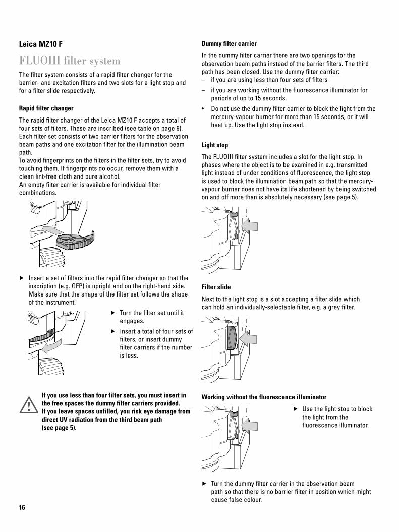
Dummy filter carrier
In the dummy filter carrier there are two openings for the observation beam paths instead of the barrier filters . The third path has been closed . Use the dummy filter carrier:– if you are using less than four sets of filters
– if you are working without the fluorescence illuminator for periods of up to 15 seconds .
• Donotusethedummyfiltercarriertoblockthelightfromthemercury-vapour burner for more than 15 seconds, or it will heat up . Use the light stop instead .
Light stop
The FLUOIII filter system includes a slot for the light stop . In phases where the object is to be examined in e .g . transmitted light instead of under conditions of fluorescence, the light stop is used to block the illumination beam path so that the mercury-vapour burner does not have its life shortened by being switched on and off more than is absolutely necessary (see page 5) .
Filter slide
Next to the light stop is a slot accepting a filter slide which can hold an individually-selectable filter, e .g . a grey filter .
Working without the fluorescence illuminator
▶ Use the light stop to block the light from the fluorescence illuminator .
▶ Turn the dummy filter carrier in the observation beam path so that there is no barrier filter in position which might cause false colour .
16
Leica MZ10 F
FLUOIII filter systemThe filter system consists of a rapid filter changer for the barrier- and excitation filters and two slots for a light stop and for a filter slide respectively .
Rapid filter changer
The rapid filter changer of the Leica MZ10 F accepts a total of four sets of filters . These are inscribed (see table on page 9) . Each filter set consists of two barrier filters for the observation beam paths and one excitation filter for the illumination beam path .To avoid fingerprints on the filters in the filter sets, try to avoid touching them . If fingerprints do occur, remove them with a clean lint-free cloth and pure alcohol .An empty filter carrier is available for individual filter combinations .
▶ Insert a set of filters into the rapid filter changer so that the inscription (e .g . GFP) is upright and on the right-hand side . Make sure that the shape of the filter set follows the shape of the instrument .
▶ Turn the filter set until it engages .
▶ Insert a total of four sets of filters, or insert dummy filter carriers if the number is less .
If you use less than four filter sets, you must insert in the free spaces the dummy filter carriers provided. If you leave spaces unfilled, you risk eye damage from direct UV radiation from the third beam path (see page 5).
17
Use
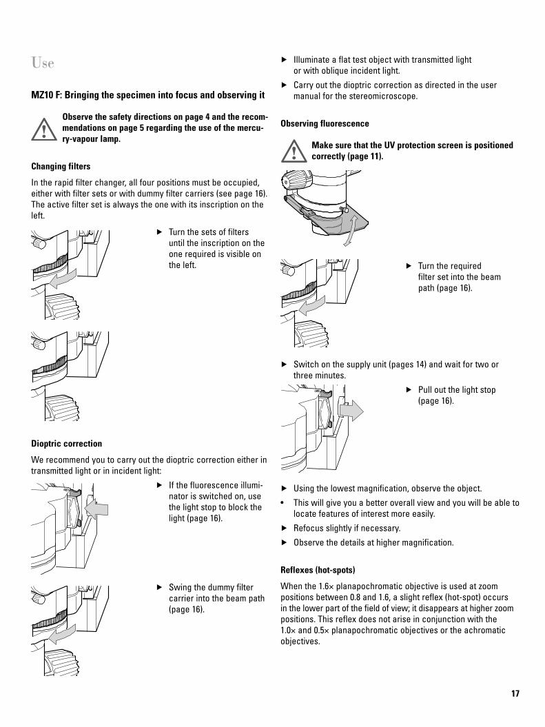
MZ10 F: Bringing the specimen into focus and observing it
Observe the safety directions on page 4 and the recom-mendations on page 5 regarding the use of the mercu-ry-vapour lamp.
Changing filters
In the rapid filter changer, all four positions must be occupied, either with filter sets or with dummy filter carriers (see page 16) . The active filter set is always the one with its inscription on the left .
▶ Turn the sets of filters until the inscription on the one required is visible on the left .
Dioptric correction
We recommend you to carry out the dioptric correction either in transmitted light or in incident light:
▶ If the fluorescence illumi-nator is switched on, use the light stop to block the light (page 16) .
▶ Swing the dummy filter carrier into the beam path (page 16) .
▶ Illuminate a flat test object with transmitted light or with oblique incident light .
▶ Carry out the dioptric correction as directed in the user manual for the stereomicroscope .
Observing fluorescence
Make sure that the UV protection screen is positioned correctly (page 11).
▶ Turn the required filter set into the beam path (page 16) .
▶ Switch on the supply unit (pages 14) and wait for two or three minutes .
▶ Pull out the light stop (page 16) .
▶ Using the lowest magnification, observe the object .
• Thiswillgiveyouabetteroverallviewandyouwillbeabletolocate features of interest more easily .
▶ Refocus slightly if necessary .
▶ Observe the details at higher magnification .
Reflexes (hot-spots)
When the 1 .6× planapochromatic objective is used at zoom positions between 0 .8 and 1 .6, a slight reflex (hot-spot) occurs inthelowerpartofthefieldofview;itdisappearsathigherzoom positions . This reflex does not arise in conjunction with the 1 .0× and 0 .5× planapochromatic objectives or the achromatic objectives .
18
Overview
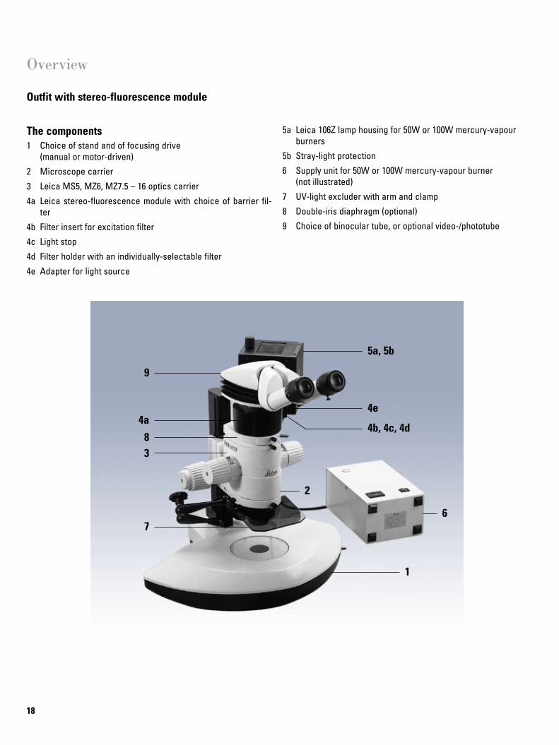
Outfit with stereo-fluorescence module
The components1 Choice of stand and of focusing drive
(manual or motor-driven)
2 Microscope carrier
3 Leica MS5, MZ6, MZ7 .5 – 16 optics carrier
4a Leica stereo-fluorescence module with choice of barrier fil-ter
4b Filter insert for excitation filter
4c Light stop
4d Filter holder with an individually-selectable filter
4e Adapter for light source
5a, 5b
4e
4b, 4c, 4d
6
1
2
9
4a
83
7
5a Leica 106Z lamp housing for 50W or 100W mercury-vapour burners
5b Stray-light protection
6 Supply unit for 50W or 100W mercury-vapour burner (not illustrated)
7 UV-light excluder with arm and clamp
8 Double-iris diaphragm (optional)
9 Choice of binocular tube, or optional video-/phototube
19
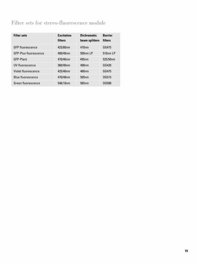
Filter sets Excitation Dichromatic Barrier filters beam splitters filters
GFP fluorescence 425/60nm 470nm GG475
GFP-Plus fluorescence 480/40nm 505nm LP 510nm LP
GFP-Plant 470/40nm 495nm 525/50nm
UV fluorescence 360/40nm 400nm GG420
Violet fluorescence 425/40nm 460nm GG475
Blue fluorescence 470/40nm 505nm OG515
Green fluorescence 546/10nm 565nm OG590
Filter sets for stereo-fluorescence module
20
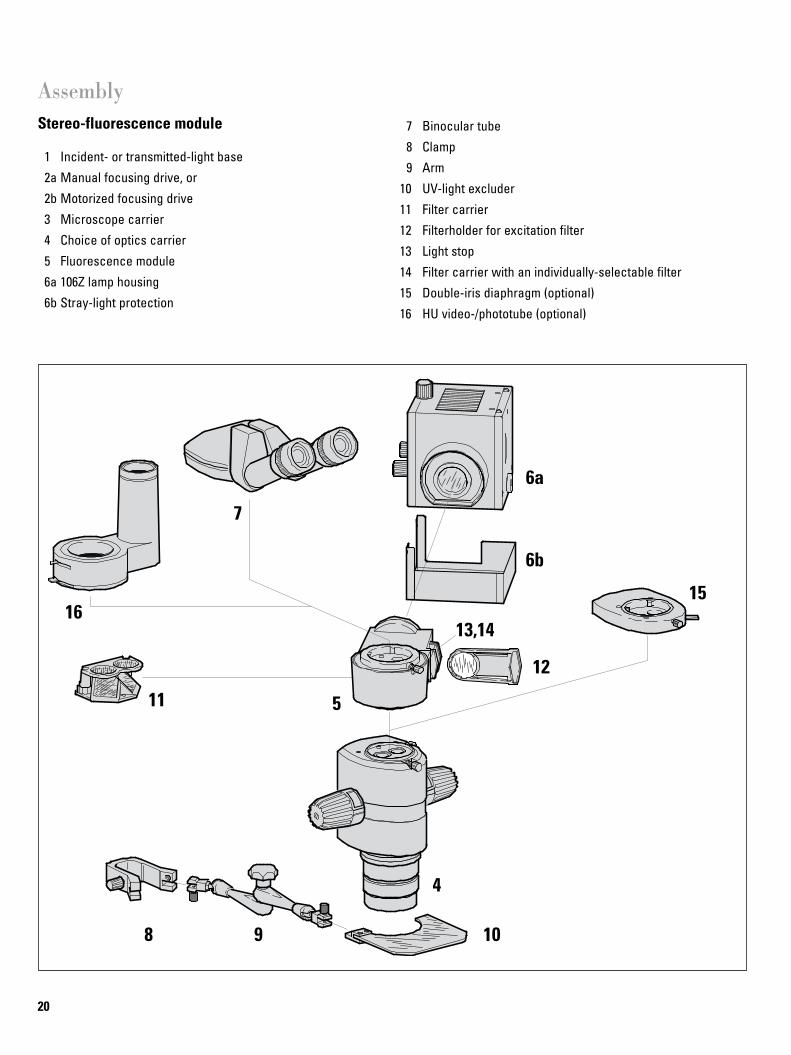
AssemblyStereo-fluorescence module
1 Incident- or transmitted-light base
2a Manual focusing drive, or
2b Motorized focusing drive
3 Microscope carrier
4 Choice of optics carrier
5 Fluorescence module
6a 106Z lamp housing
6b Stray-light protection
7 Binocular tube
8 Clamp
9 Arm
10 UV-light excluder
11 Filter carrier
12 Filterholder for excitation filter
13 Light stop
14 Filter carrier with an individually-selectable filter
15 Double-iris diaphragm (optional)
16 HUvideo-/phototube(optional)
4
5
6a
13,14
12
15
7
16
11
98 10
6b
21
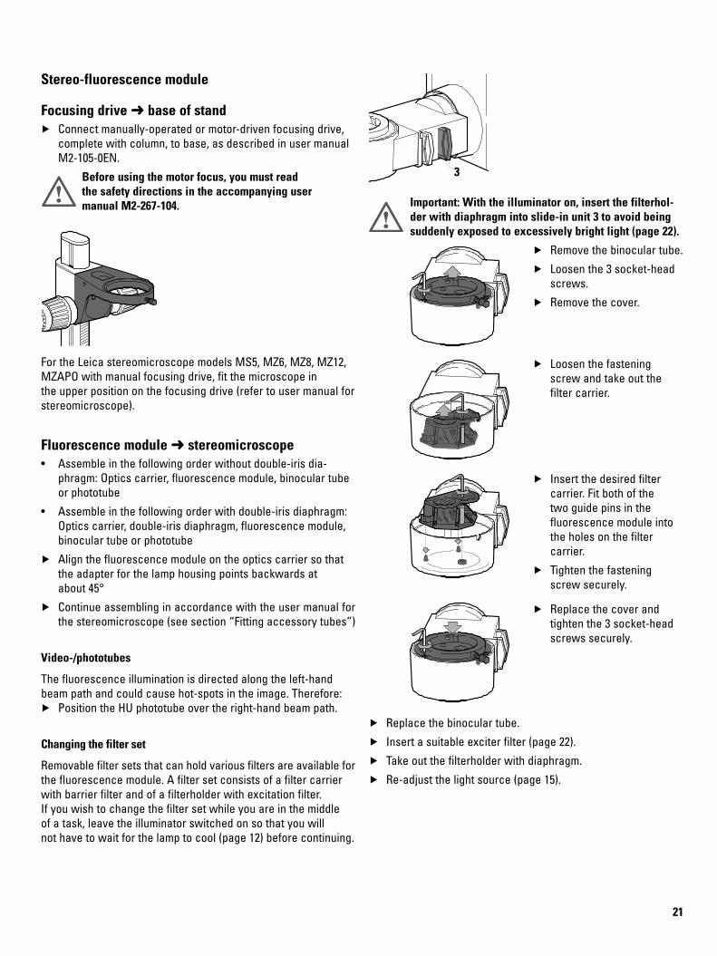
Important: With the illuminator on, insert the filterhol-der with diaphragm into slide-in unit 3 to avoid being suddenly exposed to excessively bright light (page 22).
▶ Remove the binocular tube .
▶ Loosen the 3 socket-head screws .
▶ Remove the cover .
▶ Loosen the fastening screw and take out the filter carrier .
▶ Insert the desired filter carrier . Fit both of the two guide pins in the fluorescence module into the holes on the filter carrier .
▶ Tighten the fastening screw securely .
▶ Replace the cover and tighten the 3 socket-head screws securely .
▶ Replace the binocular tube .
▶ Insert a suitable exciter filter (page 22) .
▶ Take out the filterholder with diaphragm .
▶ Re-adjust the light source (page 15) .
Stereo-fluorescence module
Focusing drive ➜ base of stand▶ Connect manually-operated or motor-driven focusing drive,
complete with column, to base, as described in user manual M2-105-0EN .
Before using the motor focus, you must read the safety directions in the accompanying user manual M2-267-104.
For the Leica stereomicroscope models MS5, MZ6, MZ8, MZ12, MZAPO with manual focusing drive, fit the micro scope in the upper position on the focusing drive (refer to user manual for stereomicroscope) .
Fluorescence module ➜ stereomicroscope• Assembleinthefollowingorderwithoutdouble-irisdia-
phragm: Optics carrier, fluorescence module, bin ocular tube or phototube
• Assembleinthefollowingorderwithdouble-irisdiaphragm:Optics carrier, double-iris diaphragm, fluorescence module, bin ocu lar tube or phototube
▶ Align the fluorescence module on the optics carrier so that the adapter for the lamp housing points backwards at about 45°
▶ Continue assembling in accordance with the user manual for the stereomicroscope (see section “Fitting accessory tubes”)
Video-/phototubes
The fluorescence illumina tion is directed along the left-hand beam path and could cause hot-spots in the image . Therefore:▶ PositiontheHUphototubeovertheright-handbeampath.
Changing the filter set
Removable filter sets that can hold various filters are available for the fluorescence module . A filter set consists of a filter carrier with barrier filter and of a filterholder with excitation filter . If you wish to change the filter set while you are in the middle of a task, leave the illuminator switched on so that you will not have to wait for the lamp to cool (page 12) before continuing .
3
22
AssemblyStereo-fluorescence module
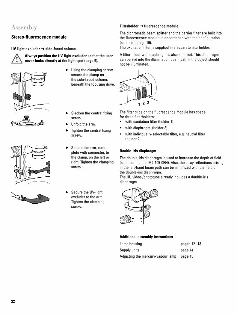
UV-light excluder ➜ side-faced column
Always position the UV-light excluder so that the user never looks directly at the light spot (page 5).
▶ Using the clamping screw, secure the clamp on the side- faced column, beneath the focusing drive .
▶ Slacken the central fixing screw .
▶ Unfold the arm .
▶ Tighten the central fixing screw .
▶ Secure the arm, com-plete with connector, to the clamp, on the left or right . Tighten the clamping screw .
▶ Secure the UV-light excluder to the arm . Tighten the clamping screw .
Filterholder ➜ fluorescence module
The dichromatic beam splitter and the barrier filter are built into the fluorescence module in accordance with the configuration (see table, page 19) .The excitation filter is supplied in a separate filterholder .
A filterholder with diaphragm is also supplied . This diaphragm can be slid into the illumination beam path if the object should not be illuminated .
The filter slide on the fluorescence module has space for three filterholders:• withexcitationfilter(holder1)
• withdiaphragm(holder3)
• withindividually-selectablefilter,e.g.neutralfilter (holder 2) .
Double-iris diaphragm
The double-iris diaphragm is used to increase the depth of field (see user manual M2-105-0EN) . Also, the stray reflections arising in the left-hand beam path can be minimized with the help of the double-iris diaphragm .TheHUvideo-/phototubealreadyincludesadouble-iris diaphragm .
Additional assembly instructions
Lamp housing pages 12–13
Supply units page 14
Adjusting the mercury-vapour lamp page 15
1 2 3
23
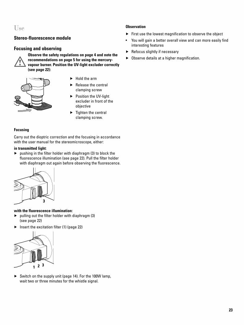
UseStereo-fluorescence module
Focusing and observingObserve the safety regulations on page 4 and note the recommendations on page 5 for using the mercury-vapour burner. Position the UV-light excluder correctly (see page 22):
▶ Holdthearm
▶ Release the central clamping screw
▶ Position the UV-light excluder in front of the objective
▶ Tighten the central clamping screw .
Focusing
Carry out the dioptric correction and the focusing in accordance with the user manual for the stereo microscope, either:
in transmitted light: ▶ pushing in the filter holder with diaphragm (3) to block the
fluores cence illumina tion (see page 22) . Pull the filter holder with diaphragm out again before obser ving the fluorescence .
with the fluorescence illumination:▶ pulling out the filter holder with diaphragm (3)
(see page 22)
▶ Insert the excitation filter (1) (page 22)
▶ Switch on the supply unit (page 14) . For the 100W lamp, wait two or three minutes for the whistle signal .
1 2 3
3
Observation
▶ First use the lowest magnification to observe the object
• Youwillgainabetteroverallviewandcanmoreeasilyfind interesting features
▶ Refocus slightly if necessary
▶ Observe details at a higher magnification .
Leica Microsystems – the brand for outstanding products
Leica Microsystems – an international company with a strong network of customer services.Australia: Gladesville Tel . +61 2 9879 9700 Fax +61 2 9817 8358Austria: Vienna Tel . +43 1 486 80 50 0 Fax +43 1 486 80 50 30Canada: RichmondHill/Ontario Tel.+19057622000 Fax+19057628937Denmark: Herlev Tel.+4544540101 Fax+4544540111France: Rueil-Malmaison Tel . +33 1 47 32 85 85 Fax +33 1 47 32 85 86Germany: Bensheim Tel . +49 6251 136 0 Fax +49 6251 136 155Italy: Milan Tel . +39 0257 486 .1 Fax +39 0257 40 3475Japan: Tokyo Tel . + 81 3 5421 2800 Fax +81 3 5421 2896Korea: Seoul Tel . +82 2 514 65 43 Fax +82 2 514 65 48Netherlands: Rijswijk Tel . +31 70 4132 100 Fax +31 70 4132 109People’sRep.ofChina:HongKong Tel.+85225646699 Fax+85225644163Portugal: Lisbon Tel . +351 21 388 9112 Fax +351 21 385 4668Singapore Tel . +65 6779 7823 Fax +65 6773 0628Spain: Barcelona Tel . +34 93 494 95 30 Fax +34 93 494 95 32Sweden: Sollentuna Tel . +46 8 625 45 45 Fax +46 8 625 45 10Switzerland: Heerbrugg Tel.+41717263433 Fax+41717263444United Kingdom: Milton Keynes Tel . +44 1908 246 246 Fax +44 1908 609 992USA: Bannockburn/lllinois Tel . +1 847 405 0123 Fax +1 847 405 0164
and representatives of Leica Microsystems in more than 100 countries.
Leica Microsystems’ mission is to be the world’s first-choice provider of innova-tive solutions to our customers’ needs for vision, measurement and analysis of micro-structures .
Leica, the leading brand for microscopes and scientific instruments, developed from five brand names, all with a long tradition: Wild, Leitz, Reichert, Jung and Cambridge Instruments . Yet Leica symbolizes innovation as well as tradition .
In accordance with the ISO 9001 certificate, Leica Microsystems (Switzerland) Ltd, Business Unit Stereo & Macroscope Systems has at its disposal a management system that meets the re-quirements of the international standard for quality management . In addition, production meets the requirements of the international standard ISO 14001 for environmental management .
The companies of the Leica Micro-systems Group operate international-ly in three business segments, where we rank with the market leaders .
• Microscopy SystemsOur expertise in microscopy is the basis for all our solutions for visuali-zation, measurement and analysis of micro-structures in life sciences and industry . With confocal laser techno-logy and image analysis systems, we provide three-dimensional viewing facilities and offer new solutions for cytogenetics, pathology and materi-als sciences .
• Specimen PreparationWe provide comprehensive systems and services for clinical histo- and cytopathology applications, bio-medical research and industrial quality assurance . Our product range includes instruments, systems and consumables for tissue infiltration and embedding, microtomes and cry-ostats as well as automated stainers and coverslippers .
• Medical EquipmentInnovative technologies in our surgi-cal microscopes offer new therapeu-tic approaches in microsurgery .
Illus
trat
ions
, des
crip
tions
and
tech
nica
l dat
a ar
e no
t bin
ding
and
may
be
chan
ged
with
out n
otic
e .Pr
inte
d on
chl
orin
e-fr
ee p
aper
with
a h
igh
cont
ent o
f rec
ycle
d fib
re .
M2-160-1en•©
Leica
Microsystem
s(Switz
erland
)Ltd•CH
-943
5Hee
rbrugg
,200
6•PrintedinSwitz
erland
–II.200
6–RD
V
www .leica-microsystems .com