Embed Size (px)
Citation preview

2
Highly Informed Robotic 3d printed polygon Mesh
Lei YuTsinghua University
Yijiang HuangUniveristy of Science and Technology of China
Zhongyuan LiuArchi-solution Workshop(Beijing)
Sai XiaoArchi-solution Workshop(Beijing)
A Novel Stratergy of 3D Spatial Printing
1
AbStrActThough the robotic 3D printing technology is under rapid development in the recent years, most of the research and experiments are still based on the bottom up layering process. This paper addresses a long term research into robotic 3D printed polygon mesh whose struts are directly built up and joint together as rapidly generated physical wireframes. This paper presents a novel “multi-threaded” robotic extruder as well as a technical strategy to create “printable” polygon mesh that is collision free during robotic operation. Comparing to standard 3D printing, its application in architecture demands a much larger dimension at human scale, geometrically lower resolution and relatively faster speed. Taking these features into consideration, 3D printed framework would have huge potential in building industry by combining robot arm technology together with FDM 3D printing technology. Currently, this methodology of rapid prototyping could be potentially applied on the pre-fabricated building components, especially for the ones with uniformed parabolic features. Owning to the mechanical feature of the robot arm, the most crucial challenge of this research would be the consistency of none-stop automate control. Here, algorithm is employed not only to predict and solve problems, but also to optimize for a highly efficient constructing process in coordination of robotic 3D printing system. Since every stroke of the wireframe contains many parameters and calculations in order to reflect its native organization and structure, this robotic 3D printing process would require processing an intensive amount of data in the back stage.
Ligang LiuUniveristy of Science and Technology of China
Guoxian SongUniveristy of Science and Technology of China
Yanxin WangArchi-solution Workshop(Beijing)
3TOPiC (ACADiA team will fill in)
2
3
3D PrinteD FrAmeWorkPolygon mesh is often known as a collection of vertices, edges and faces that defines the shape of a polyhedral object in 3D computer graphics and solid modeling. Typical 3D printing technique slice the polygon mesh with evenly spaced horizontal plans, and rebuild the model through layering of contour crafted slices. But this method of fabrication is slow to satisfy the scale of production for the building industry. When Solid Doodler came out a few years ago, its spatial thermoplastic extrusion has drawn much attention. Especially with its powerful and flexible maneuver that could potentially simulate the performance of human arm, industrial robot arm has proven to be a perfect choice for the task.
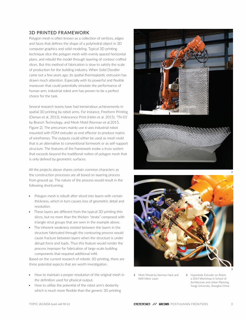
Several research teams have had tremendous achievements in spatial 3D printing by robot arms. For instance, Freeform Printing (Oxman et al. 2013), iridescence Print (Helm et al. 2015), ‘TN-01’ by Branch Technology, and Mesh Mold (Norman et al.2015, Figure 2). The precursors mainly use 6-axis industrial robot mounted with FDM extruder as end effector to produce matrix of wireframes. The outputs could either be used as mesh mold that is an alternative to conventional formwork or as self-support structure. The features of the framework evoke a truss system that exceeds beyond the traditional notion of polygon mesh that is only defined by geometric surfaces.
All the projects above shares certain common characters as the construction processes are all based on layering process from ground up. The nature of the process would result in the following shortcoming:
• Polygon mesh is rebuilt after sliced into layers with certain thickness, which in turn causes loss of geometric detail and resolution.
• These layers are different from the typical 3D printing thin slices, but no more than the thicken “strata” composed with triangle strut groups that are seen in the example above.
• The inherent weakness existed between the layers in the structure fabricated through the contouring process would cause fracture between layers when the structure is under abrupt force and loads. Thus this feature would render the process improper for fabrication of large-scale building components that required additional infill.
Based on the current research of robotic 3D printing, there are three potential aspects that are worth investigation.
• How to maintain a proper resolution of the original mesh in the definition used for physical output.
• How to utilize the potential of the robot arm’s dexterity which is much more flexible than the generic 3D printing
2 Mesh Mould by Norman Hack and Willi Viktor Lauer
3 Hyperbolic Extruder on Robot, a 2014 Workshop in School of Architecture and Urban Planning, Tongji University, Shanghai China

4
5
4
CNC machine.• How to take advantage of the geometrical feature of the
original polygon mesh to generate a 3D spatial wireframe and reinforce its strength in all directions.
robotic 3D SPAtiAL PrinteD PoLYGon meSHin the past two years, we have dedicated an incessant effort on how to employ industrial robot arm on a rapid construction for framework. This combination has shown great prospective that could fundamentally alter the conventional method of concrete mold-work, which has always being facing the critic of overly high cost and being labor intensive, especially for customized building parts. Our research aims on a novel direction that mesh framework could be strategically 3D printed according to its native topographies. The key focus of the research is the spatial configuration of the 3D printing process and its strength, such as the span, deformation, connection and its generation sequence.it contains two stages that involves different attitude toward material configuration. The former is based on multi-threaded extrusion, while the latter is single-threaded extrusion.
multi-threaded extrusion and Form DefinitionThe goal of this research stage is to create standalone lineal overhang, which is capable of rising up as a self-support structure. in order to increase the thin plastic filament’s capacity for a larger span, this research concentrated heavily on the design of the robot arm’s end effector, which could produce
significant composited extrusion embedded with more structural freedom.
The spider silk was investigated under microscope for more evidence. it is to our surprise discovering that the profile of spider silk displays as a serial of spindle knots joint together under the microscope at 200um. After a few tests with hand-made models lifting the same block, including a model of one center tread surrounded by two or three corrugated ABS filaments (Figure 3&4), we have discovered the model that is highly efficient in increasing toughness of the extrusion through the spatial configurations.
Design decision of robot’s ‘hand’ was paid on creating these regulating knots along the motion path of the robot. There are four nozzles proposed required for this mechanism. One center nozzle extruding a fat straight thread, and the other three outer nozzles generates undulating curves that meet periodically with the center thread (Figure 5). The outer nozzles are fixed onto a sweeping mechanism driven by stepper motors to ensure their open-close movements. Extruder and robot arm are synchronized by Arduino system (Figure 6). There are many essential driving parameters, such as robot effector’s moving speed, extruding speeds, rotation speed of the center sweeper, nozzle temperature etc. All of the parameters need to be coordinated in order to create a smooth lineal profile similar to the hand-made test model.
Finally, this robotic 3D printer generates a hyperbolic curve
6
Highly Informed Robotic 3D Printed Polygon Mesh, Yu

5TOPiC (ACADiA team will fill in)
7
4 Spider Silk Macro Pictures and Simulating Test
5 Robot End Effector Design and Assembly
6 Arduino Control System to synchronize 5 stepper motors with 6 axis industrial robot
7 Process of Hyperbolic Extrusion
that confronts extra geometric and structural challenges(Figure 7). Different from the arch model with two anchor points, this hyperbolic helix has only one standing point while self-support by its own rigidity relying on its own biomimitic configuration. We should also be aware that the ABS filament, a common thermalplastic, has a significant shrinkage rate, which means that after the melted plastic extrusion cools down, the shape will deform slightly, which could cause joint dispoisitions under some circumstance. Even though the multi-threaded extrusion gains certain achievement with its attractive performance,three main concerns drives the research into the second stage – a massive structural frame:
• The deformation affected by material shrinkage and gravity will cause joint to dislocate for the adjecent struts to connect.
• The hyperbolic configuration is hard to connect with each other without extra supports.
• The multi-threaded robot end effector is too big to avoid collision with the existing 3D printed elements, and always causes robot to run out of working range.
Single-threaded extrusion and Form DefinitionFrom the previous study, we have come to a conclusion that in order to achieve a better-defined 3D printed mesh, the robot effector should be as small as possible for the process to be collision free. Therefore, we started to reconsider single-treaded extrusion. Even though we abandoned the multi-threaded extrusion approach, much of the experience and parameters are inherited into the upcoming stage.
industry robot has inborn constrains which has to be considered at each step of motion to plan a valid working path. The caution of motion planning includes existent obstacles in working space, limits from articulated singularities and articulated robot joint angle. According to the American National Standard for industrial Robots and Robot Systems, singularity is defined as a condition caused by the collinear alignment of two or more robot axes resulting in unpredicted robot motion and velocities.
Singularities occur as:
• Wrist singularities: occurs when the axes of Joints 4 and 6 are aligned;
• Alignment singularities: occurs when Joint 6(wrist) and Joint 1 axes are aligned;
• Elbow singularities: occurs when the arm is fully extended. in this case, as the elbow joint becomes further extended, higher joint speeds are required to maintain constant Cartesian speed. The robot cannot extend beyond its reach.
These constrain effects the tilling style construction process less than the ‘orientation style’ construction - the method of approach involved in this paper. if the effector’s orientation and the space angle of mesh edge are to be coped within certain angle for making straight and strong struts in our case, there are much more parameters needed to be systematically managed. The data requires careful calculation and simulation for validation and optimization beforehand, testing for any possibility of halting during fabrication.
Mechanism of robot end effector design and the proper
6
9
8
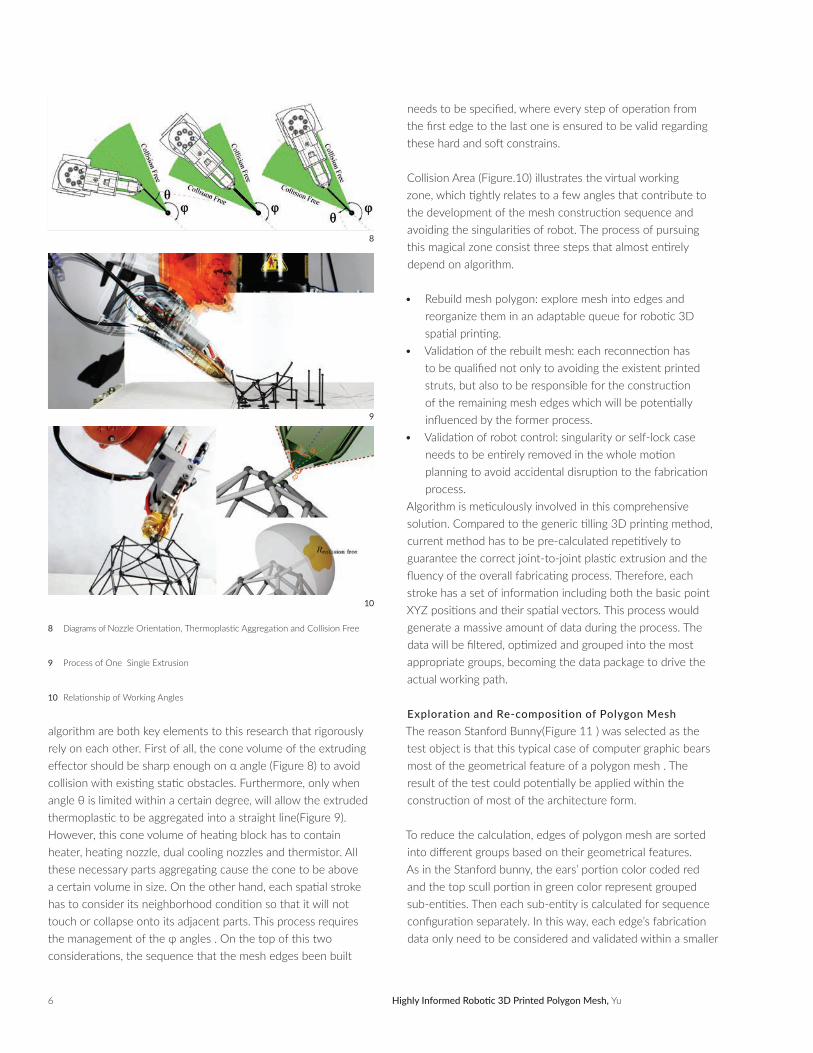
needs to be specified, where every step of operation from the first edge to the last one is ensured to be valid regarding these hard and soft constrains.
Collision Area (Figure.10) illustrates the virtual working zone, which tightly relates to a few angles that contribute to the development of the mesh construction sequence and avoiding the singularities of robot. The process of pursuing this magical zone consist three steps that almost entirely depend on algorithm.
• Rebuild mesh polygon: explore mesh into edges and reorganize them in an adaptable queue for robotic 3D spatial printing.
• Validation of the rebuilt mesh: each reconnection has to be qualified not only to avoiding the existent printed struts, but also to be responsible for the construction of the remaining mesh edges which will be potentially influenced by the former process.
• Validation of robot control: singularity or self-lock case needs to be entirely removed in the whole motion planning to avoid accidental disruption to the fabrication process.
Algorithm is meticulously involved in this comprehensive solution. Compared to the generic tilling 3D printing method, current method has to be pre-calculated repetitively to guarantee the correct joint-to-joint plastic extrusion and the fluency of the overall fabricating process. Therefore, each stroke has a set of information including both the basic point XYZ positions and their spatial vectors. This process would generate a massive amount of data during the process. The data will be filtered, optimized and grouped into the most appropriate groups, becoming the data package to drive the actual working path.
Exploration and Re-composition of Polygon MeshThe reason Stanford Bunny(Figure 11 ) was selected as the test object is that this typical case of computer graphic bears most of the geometrical feature of a polygon mesh . The result of the test could potentially be applied within the construction of most of the architecture form.
To reduce the calculation, edges of polygon mesh are sorted into different groups based on their geometrical features. As in the Stanford bunny, the ears’ portion color coded red and the top scull portion in green color represent grouped sub-entities. Then each sub-entity is calculated for sequence configuration separately. in this way, each edge’s fabrication data only need to be considered and validated within a smaller
10
8 Diagrams of Nozzle Orientation, Thermoplastic Aggregation and Collision Free
9 Process of One Single Extrusion
10 Relationship of Working Angles
algorithm are both key elements to this research that rigorously rely on each other. First of all, the cone volume of the extruding effector should be sharp enough on α angle (Figure 8) to avoid collision with existing static obstacles. Furthermore, only when angle θ is limited within a certain degree, will allow the extruded thermoplastic to be aggregated into a straight line(Figure 9). However, this cone volume of heating block has to contain heater, heating nozzle, dual cooling nozzles and thermistor. All these necessary parts aggregating cause the cone to be above a certain volume in size. On the other hand, each spatial stroke has to consider its neighborhood condition so that it will not touch or collapse onto its adjacent parts. This process requires the management of the φ angles . On the top of this two considerations, the sequence that the mesh edges been built
Highly Informed Robotic 3D Printed Polygon Mesh, Yu
7TOPiC (ACADiA team will fill in)
set instead of the whole. Even though it still copes with the layering concept in certain sense, these sub-entities concept investigates in a much larger volumetric structure than flat slices. This methodology takes not only point-to-point definition into consideration, but also point-to-point orientation.
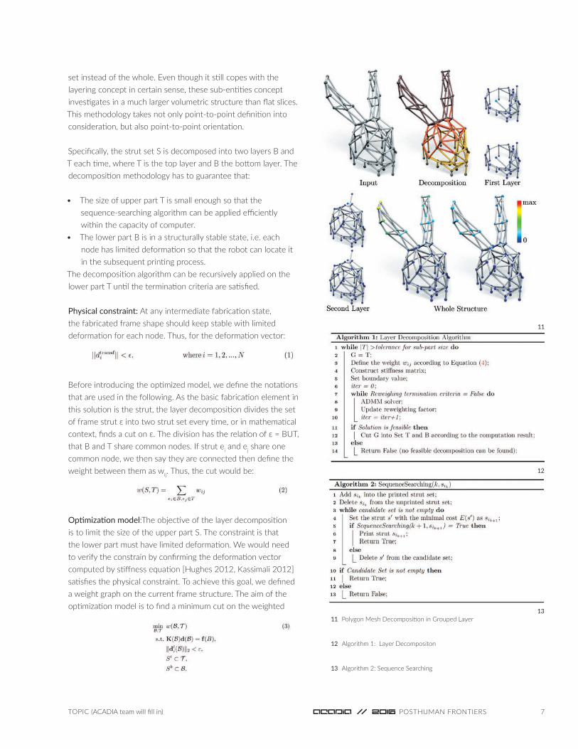
Specifically, the strut set S is decomposed into two layers B and T each time, where T is the top layer and B the bottom layer. The decomposition methodology has to guarantee that:
• The size of upper part T is small enough so that the sequence-searching algorithm can be applied efficiently within the capacity of computer.
• The lower part B is in a structurally stable state, i.e. each node has limited deformation so that the robot can locate it in the subsequent printing process.
The decomposition algorithm can be recursively applied on the lower part T until the termination criteria are satisfied.
Physical constraint: At any intermediate fabrication state, the fabricated frame shape should keep stable with limited deformation for each node. Thus, for the deformation vector:
Before introducing the optimized model, we define the notations that are used in the following. As the basic fabrication element in this solution is the strut, the layer decomposition divides the set of frame strut ε into two strut set every time, or in mathematical context, finds a cut on ε. The division has the relation of ε = BUT, that B and T share common nodes. if strut ei and ej share one common node, we then say they are connected then define the weight between them as wij. Thus, the cut would be:
Optimization model:The objective of the layer decomposition is to limit the size of the upper part S. The constraint is that the lower part must have limited deformation. We would need to verify the constrain by confirming the deformation vector computed by stiffness equation [Hughes 2012, Kassimali 2012]satisfies the physical constraint. To achieve this goal, we defined a weight graph on the current frame structure. The aim of the optimization model is to find a minimum cut on the weighted
12
11
1311 Polygon Mesh Decomposition in Grouped Layer
12 Algorithm 1: Layer Decompositon
13 Algorithm 2: Sequence Searching

8
14
15
14 Algorithm 3 for Fabrication Sequence Design
15 Extruding Sequence Probing Simulation
Highly Informed Robotic 3D Printed Polygon Mesh, Yu
graph with stable constraint:
Here St and Sb are respectively the top and bottom boundary struts of the input wireframe. K is the stiffness matrix of sub-structure B and f is the gravity forces that associated bending moment of the nodes [Hughes 2012, Kassimali 2012].
To make the size of set S small, the cut should be close to the top boundary. To achieve this purpose, we define weight wij as:
Here, parameter β is used to control the weight distribution and h2(vk) is the normalized height of the node vk. in this way, the weights of the nodes close to the top boundary are small, which makes the cut boundary as high as possible and thus the top sub-part T is as small as possible.
Numerical computation of the decomposition algorithm:This is a constrained discrete optimization problem. We first simplify the binary optimization problem into a continuous optimization problem and then use iterative reweighting scheme in [Lai et al. 2013] to solve this constrained optimization problem. in each iteration reweighing loops, we adopt the Alternating Direction Method of Multipliers (ADMM) [Boyd et al. 2011] to solve sub-problems, as shown in Algorithm 1(figure12).
Fabrication Sequence FindingCollision is the most critical concern in this phase of the fabrication sequence. Quite different from the tiling method in which nozzle is strictly perpendicular to the build plate, the ‘orientation style’ extrusion in our approach put extruder tip inside the existent wireframe in most of situations. Hence, collision possibility has to be evaluated carefully for every single stroke. After many experiments, when extruder nozzle extrudes along the direction of each polygon edge mesh, the cone volume, defined by angle θ (Figure 8), provides a partial solution to avoid the obstacles during extrusion.
To compute the complete fabrication sequence, the first step is to consider how to choose the next strut to print at each state. Assume we have already printed k struts, which form sub-structure Sk. Now we have to find an optimal strut with minimal cost to use for subsequent printing.
We construct a candidate set of eligible struts for current decisive state, where each eligible strut s in the set satisfies:
• sis connected to the current printed structure.• There are collision-free extruder orientations eligible for
the printing s.There might be several eligible struts in the candidate set. We then introduce costs evaluation for each candidate to help us select the most appropriate one.
The sequence-searching algorithm 2 (Figure 13) is a kind of searching strategy with quick pruning, using the evaluated cost as a guide, to quickly prune off unnecessary items to avoid searching on unnecessary printing sequence.
overall algorithmThis re-composition is also considered as a reconstruction of an architectural framework. Each sub-entity contains a structure-like framework by means of its triangle formation. C++ program is chosen to work with Grasshopper in Rhinoceros environment (Figure 14). Genetic algorithm, one of Heuristic algorithms, is employed in this case for a suitable solution to the decomposition and re-organization. (Latombe 2012; Choset 2005). Similar algorithm is applied in the fabrication sequence finding as well.
However, more collision free zone is defined through study of the kinetic feature of industrial robot. This six axis robot performs in a way similar to the human limbs but with a lot more strength and precision. Through calculation, there are multiple angles free from collision, but there are only a few candidates that are compatible with the next strokes and

9TOPiC (ACADiA team will fill in)
16 Validation Between Virtual Simulation and Physical Fabrication
collision free. So the algorithm of sequence design supposes to optimize not only the next single struts, but the rest of its group. After tapping all related information into algorithm (Figure 14), the result is quite unexpected. The optimal sequence is not a continuous polyline making motion, but a discrete order. in (Figure 15), the struts are color coded from yellow to orange according to their order in the construction sequence. The yellow struts have more priority than the orange. in the optimal sequence, the extruder will generate the struts with similar spatial directions first. Then robot changes its gesture to work on another direction to close the polygon mesh. During the construction process, there are lots of transitional moments that robot turns its axis drastically from one gesture into another. These transitions actually permit the, machine to 3D print in a fluent sequence by skipping any cessation caused by robot’s over-range and singularities.
Spatial Printing material Almost all of the spatial thermoplastic extrusion projects confront the same trouble: shrinkage. in the multi-threaded extrusion project, the outer nozzles have to swing a little more toward the center tip to allow all four threads running into each other. This is because ABS thread has a fact of certain shrinkage during cooling phase. This phenomenon brings more drawbacks in single-treaded frame printing. Because of shrinkage and self-weight, the single standalone strut, who does not have any support from adjacent elements, will have physical deviation causing the end point to lose its position for the next member to
pick up. As consequence, the rest struts will not keep the relay and end up as a disastrous mess in the end.
Many thermoplastic filaments, such as ABS and PLA, were tested and proven to have similar deviation problem. PLA has a little more advantage over ABS who has higher melting temperature and longer cooling time. A custom-made PLA mixed with certain amount of carbon powder is applied to fix this problem. As expected, the strut extruded by this composite PLA filament reduces the deviation into an acceptable range.
Robot Control Based on MathematicsRobots only works in certain range due to mechanical constrain. if it goes beyond this range, it would self-lock and causes the whole process to halt. There is also a singularity problem that the alignment of 4th axis and 6th axis causes robot to behave in an unpredictable manner, followed by an immediately halts again. it means that the sets of working sequences figured out from sequence design have to be re-selected to avoid these issues. KUKAprc, a Grasshopper plugin used for generating KUKA robot code, is taken into consideration in this phase. On one hand, KUKAprc coordinates with algorithm that could simulate the whole printing process in Rhinoceros and eliminate the bad key frames. On the other hand, KUKAprc helps to pipe out the final robotic Gcode.
The custom-made extruder is installed on the 6th robot axis’s plate. To reduce extruder’s size, stepper motor is installed on
10
18
17
19
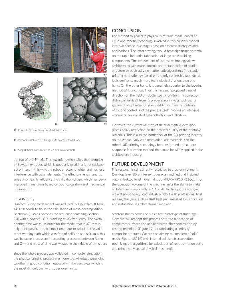
17 Concrete Cement Spary on Metal Wireframe
18 Voronoi Tessellated 3D Ploygon Mesh of Stanford Bunny
19 Soap Bubbles, New York, 1945-6 by Bernice Abbott
Highly Informed Robotic 3D Printed Polygon Mesh, Yu
the top of the 4th axis. This extruder design takes the reference of Bowden extruder, which is popularly used in a lot of desktop 3D printers in this way, the robot effector is lighter and has less interference with other elements. The effector’s length and tip angle also heavily influence the validation phase, which has been improved many times based on both calculation and mechanical optimization.
Final PrintingStanford Bunny mesh model was reduced to 179 edges. it took 14.09 seconds to finish the calculation of mesh decomposition (section2.3), 36.61 seconds for sequence searching (section 2.4) with a powerful CPU working at 4G frequency. The overall printing time was 91 minutes for the model that is 371mm in height. However, it took almost one hour to calculate the valid robot working path which was free of collision and self-lock, this was because there were interpreting processes between Rhino and C++ and most of time was wasted in the middle of transition.
Since the whole process was validated in computer simulation, the physical printing process was non-stop. All edges were joint together in good condition, especially in the ears area, which is the most difficult part with super overhangs.
concLUSionThe method to generate physical wireframe model based on FDM and robotic technology involved in this paper is divided into two consecutive stages base on different strategies and applications. The latter strategy would have significant potential on the rapid industrial fabrication of large scale building components. The involvement of robotic technology allows architects to gain more controls on the fabrication of spatial structure through utilizing mathematic algorithms. The spatial printing methodology based on the original mesh’s topological logic confronts much more technological challenge on one hand. On the other hand, it is genuinely superior to the layering method of fabrication. Thus this research proposed a novel direction on the field of robotic spatial printing. This direction distinguishes itself from its predecessor in ways such as: its geometrical optimization is embedded with many contents of robotic control, and the process itself involves an intensive amount of complicated data collection and filtration.
However, the current method of thermal melting extrusion places heavy restriction on the physical quality of the printable materials. This is also the bottleneck of the 3D printing industry on the whole. Only with more adequate materials, can the robotic 3D printing technology be transformed into a more adaptable fabrication method that could be wildly applied in the architecture industry.
FUtUre DeveLoPmentThis research is still currently restricted to a lab environment. Desktop level 3D printer extruder was modified and installed onto a desktop level industrial robot (KUKA KR10 R1100). Thus the operation volume of the machine limits the ability to make architecture components in 1:1 scale. in the upcoming stage we will adopt heavy-load industrial robot with professional heat melting glue gun, such as BAK heat gun, installed for fabrication and installation in architectural dimension.
Stanford Bunny serves only as a test prototype at this stage. Next, we will readopt this process onto the fabrication of complicate surfaces and use reinforced fiber concrete spray casting technique (Figure 17) for fabricating a series of composite products. We are also aiming to complete a ‘solid’ mesh (Figure 18&19) with internal cellular structure after optimizing the algorithms for calculation of robotic motion path, and print a truly spatial physical mesh mold.
11TOPiC (ACADiA team will fill in)
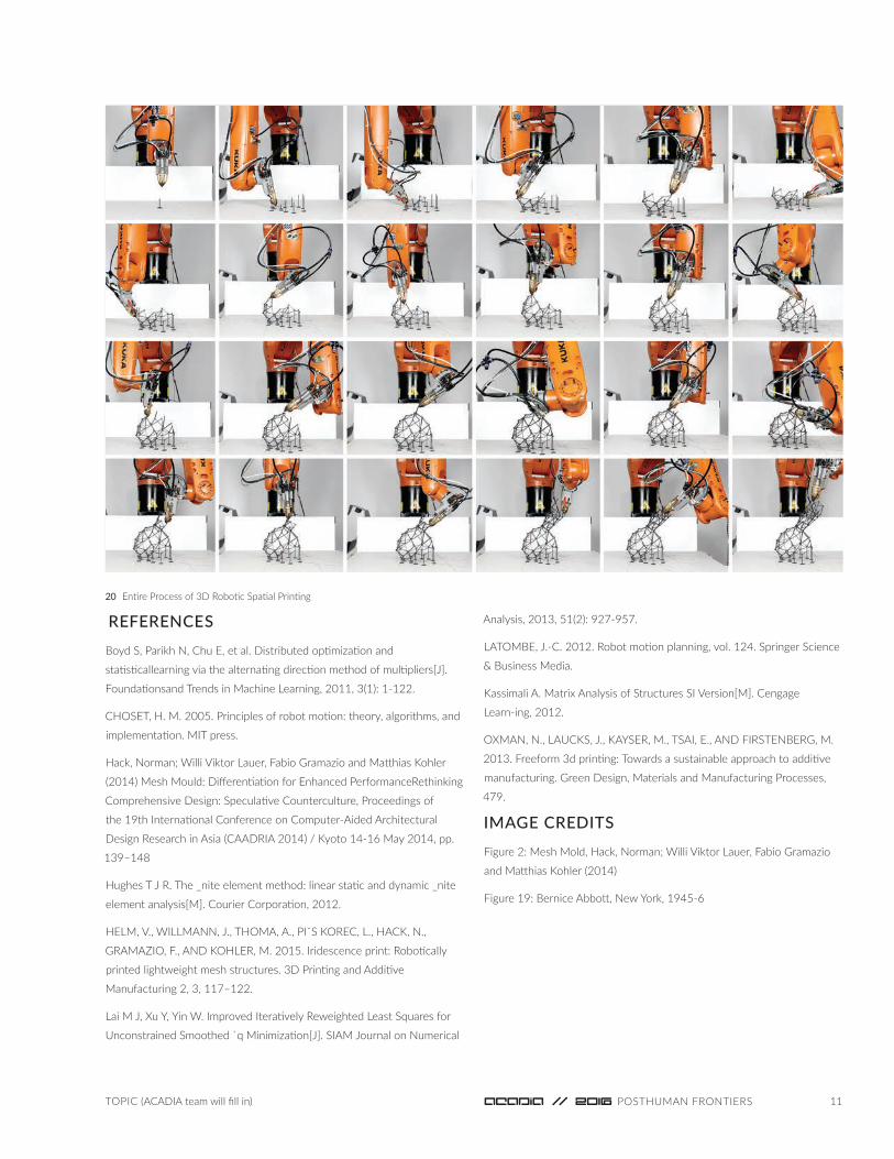
20 Entire Process of 3D Robotic Spatial Printing
reFerenceS
Boyd S, Parikh N, Chu E, et al. Distributed optimization and
statisticallearning via the alternating direction method of multipliers[J].
Foundationsand Trends in Machine Learning, 2011, 3(1): 1-122.
CHOSET, H. M. 2005. Principles of robot motion: theory, algorithms, and
implementation. MiT press.
Hack, Norman; Willi Viktor Lauer, Fabio Gramazio and Matthias Kohler
(2014) Mesh Mould: Differentiation for Enhanced PerformanceRethinking
Comprehensive Design: Speculative Counterculture, Proceedings of
the 19th international Conference on Computer-Aided Architectural
Design Research in Asia (CAADRiA 2014) / Kyoto 14-16 May 2014, pp.
139–148
Hughes T J R. The _nite element method: linear static and dynamic _nite
element analysis[M]. Courier Corporation, 2012.
HELM, V., WiLLMANN, J., THOMA, A., PiˇS KOREC, L., HACK, N.,
GRAMAZiO, F., AND KOHLER, M. 2015. iridescence print: Robotically
printed lightweight mesh structures. 3D Printing and Additive
Manufacturing 2, 3, 117–122.
Lai M J, Xu Y, Yin W. improved iteratively Reweighted Least Squares for
Unconstrained Smoothed `q Minimization[J]. SiAM Journal on Numerical
Analysis, 2013, 51(2): 927-957.
LATOMBE, J.-C. 2012. Robot motion planning, vol. 124. Springer Science
& Business Media.
Kassimali A. Matrix Analysis of Structures Si Version[M]. Cengage
Learn-ing, 2012.
OXMAN, N., LAUCKS, J., KAYSER, M., TSAi, E., AND FiRSTENBERG, M.
2013. Freeform 3d printing: Towards a sustainable approach to additive
manufacturing. Green Design, Materials and Manufacturing Processes,
479.
imAGe creDitS
Figure 2: Mesh Mold, Hack, Norman; Willi Viktor Lauer, Fabio Gramazio
and Matthias Kohler (2014)
Figure 19: Bernice Abbott, New York, 1945-6