Embed Size (px)
Citation preview

OWNER’SMANUAL
For your new boat package.

1
Welcome to the Legend family!
Please take a few minutes to read this Owner’s Manual in addition to carefully reviewing any additional manuals that correspond with your new Legend boat package. This manual will help to answer most of the remaining questions you may have regarding your new Legend boat package. If you have any questions after reading this manual, please feel free to contact your local Legend dealer.
If you are new to boating or it is your first time operating this style of boat, it is recommended you contact your local boating agency to find out how to enroll in a boater safety course prior to taking to the water.
Note: This owner’s manual is a general guide and not model specific. It may include information about features and equipment not provided on your boat package. This manual contains information about utility boats, side console boats, full windshield boats and pontoon boats. Some information pertains only to particular models and may not apply to your boat. Check with your dealer if you have any unanswered questions.
IdeNtIfIcatIoN The hull identification serial number should be included in any inquiries or when ordering parts. The identification plate is located on the upper, starboard (driver’s side) corner of the transom, or on the starboard side pontoon near the stern (back).
BOAT PACkAge InfOrMATIOn:
Owner _____________________________________________________________________________________ Date Purchased______________________________________________________________________________Address____________________________________________________________________________________Dealer _____________________________________________________________________________________Phone _____________________________________________________________________________________Address____________________________________________________________________________________Boat Model_________________________________________________________________________________Serial number________________________________________________________________________________Motor______________________________________________________________________________________Serial number_______________________________________________________________________________Trailer______________________________________________________________________________________Serial number_______________________________________________________________________________Trolling Motor________________________________________________________________________________Serial number_______________________________________________________________________________
coNgratulatIoNs On yOur new legeNd BOAT!
2
All information in this Manual is based on the latest product information available at the time of printing and is subject to change without notice. Contact your local Legend Dealer for the most recent information and update.
taBle of coNteNts:
custom legeNd glIde-oN traIler 3
winch Stand/ Strap, Jack & Dolly wheel, nuts and Bolts 3
Bearing Buddies, Inspection, Tie Downs, Adjusting your coupler, replacing your tail light 4
lauNchINg your Boat 5-6
oN the Water 7
Before leaving the dock, Leaving the dock 7
Accelerating, Accelerating with power trim, Boats equipped with full stand-up tops 8
mercury outBoard 9
Operation, Break-in procedure 9
Cowl removal, engine fuse, safety cord and dip stick locations, engine bolts, thumb screws 10
loadINg your Boat 11-12
model serIes features 13
utility, single console 13
full windshield, pontoon 14
Boat features 15
Trolling motor operation, battery locations 15
Bow panel, switches, bilge pump 16
Livewell location and operation, horn 17
fish/depth finder, circuit breakers, 12 volt outlets, seat bases 18
hoW to INstall a travel cover 19
Custom travel cover, Bow to stern cover, custom cockpit cover 19
hoW to INstall a full staNd-up top 20
WarraNty 21-22
Pro Classic Series warranty, gen X Series warranty, Pontoon Series warranty 21Legend Product Protection 21-22
3
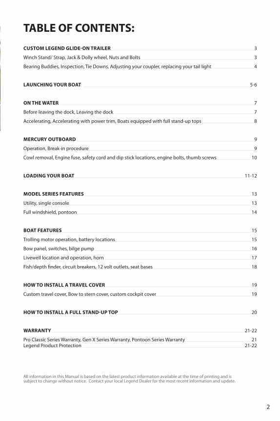
WINch staNd/strap:
ensure that the winch strap is fed under the rubber roller and the
locking clip is secured to the bow eye.
Additional bow eye safety chain should also be locked
into place.
CuSTOM LegenD gLIDe-On TrAILer
Jack & dolly Wheel:
your jack and dolly wheel is meant to assist when maneuvering your boat
and trailer. Always swivel to maximize turning room.
when trailering, pull the locking pin and rotate your jack and dolly
wheel so that it sits on a horizontal position alongside your trailer.
Make sure it is securely locked into place with the handle away from
the vehicle for increased turning room.
Nuts aNd Bolts:Visually inspect all nuts and bolts for tightness, tighten if necessary.
Locking clip
winch strap*Safety chain
High quality boats deserve high quality trailers. That’s why we choose Shoreland’r as our exclusive supplier for our Legend custom matched glide-on design. A high quality trailer means a high quality boating experience from loading and unloading to highway driving. Here are some of the features you should know before trailering your boat.
Clockwise is up
Counter clockwise is down

4
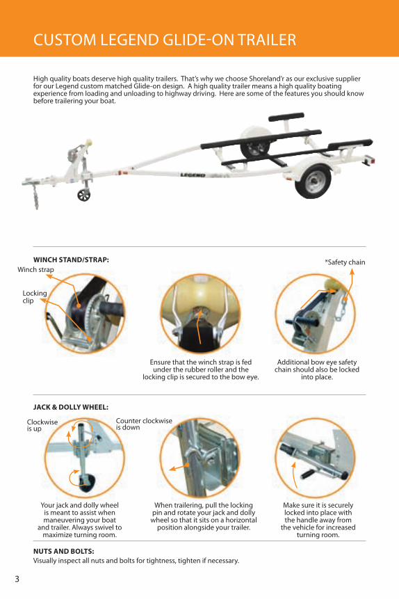
adJustINg your coupler:
reach under the coupler and raise the channel lock up. Turn the
adjusting nut clockwise to tighten and counterclockwise to loosen ball clamp
grip on the ball.
replace the hitch back on the ball and latch. repeat this process
until the ball clamp latches securely around the ball.
remember tightening the coupler does not compensate for 2” - 17/8”
ball. Be sure your ball matches your coupler every time. Legend trailers
use only 2” ball couplers.
If the piston cannot be moved, it’s time to add grease. use a hand operated grease gun and add
only enough to move the piston outward until it rocks.
Bearing buddies create a positive pressure inside the hub. Because of this constant internal pressure
inside the hub, water cannot enter.
To check the hub lubricant level, press on the edge of the spring loaded piston. If you can move or rock the piston, the hub has
sufficient grease.
tIe doWNs:your boat must be properly supported by the trailer. your boat must also stay positioned on the trailer while towing. This is accomplished by securing the boat to the trailer with tie downs. The black rubber coated hook goes on the boat, and the metal one on the trailer. Do not over tighten.
Locate the plastic tab underneath the tail light
Note: Larger trailers have two screws that are to be removed for tail light replacement.
Simply lift on the tab or unscrew both screws
The entire wiring harness assembly will drop and hang for easy bulb replacement.
Hook
Press here
Lift tab
INspectIoN:ensure to inspect lights and tighten wheel nuts and all trailer bolts after the first 100 miles and then every 300 miles for safety.
BearINg BuddIes:
replacINg your taIl lIght:

5
ensure that boat plug is properly installed.
unplug trailer lights remove trailer tie downs
ensure that safety chain and winch strap are
engaged and secured
Inspect loading ramp for under water obstacles
before backing in.
ensure that motor is tilted up
unhook
Inspect boat launch Back in until boat begins to float and ensure that motor is in water and started before releasing boat.
Check water for proper depth and for under-surface
obstacles.
LAunCHIng yOur BOAT
sImple checklIst p Before lauNchINg:p Did you get a current weather report?p Is the hull drain plug installed?p Are electrical system and navigation lights working?p Is the battery fully charged? p Are fluid levels Ok?p Have you pumped all water out of the bilge?
p Is all required safety equipment, emergency supply of food and water on board? p Are mooring lines, anchor, tool kit, first aid kit on board?p Do you have enough fuel for your trip?p Are you familiar with the area where you will be boating?p Are all required documents on board?
1.
2.
3.

6
release the safety chain and winch strap
Have someone on land holding them during launch
ensure that mooring lines are attached
Launch boat Pull trailer out of water and away from the ramp.
Allow engine to warm up at dock before getting
underway.
4. turning while towingwhen towing your trailer, note that your trailer will track a tighter turn than your towing vehicle. Make sure that when making a left or right turn, your trailer does not strike any obstruction such as trees, vehicles or even people. Be sure to inspect where you will be launching your boat. Appropriate speeds should be utilized at all times when towing a trailer. when reversing with a trailer, slower is always better.
tip: Place your hand at the bottom of your steering wheel while reversing. Move your hand in the direction your want your boat to go.
View following diagrams for backing up a trailer.
Trailer path
Vehicle path
Backing upto go leftwith trailer
Backing upto go rightwith trailer
5.
6.

7
On THe wATer
Before leavINg the dock:If gear is to be loaded, have someone on the dock pass the gear aboard instead of stepping in and out of the boat. Make sure gear is secured so it doesn’t shift or interfere with boat operation. when boarding, passengers should step into the boat one at a time. Once in, passengers not helping load gear should be seated. Position passengers and gear so that the load is balanced evenly.
leavINg the dock:
Make sure you are aware of your surroundings as you maneuver
away from the dock.
remove mooring lines and secure them inside your
boat. Maneuver away from the dock at idle speed
when all pre-departure checks are completed, you
can leave the dock
even
even
Back heavy
Left lean
front heavy
right lean

8
Boats equIpped WIth full staNd-up tops:All models with a full Stand-up Top in an unopened position should not be left up when travelling on rough waters. Only a full Stand-up Top partially or fully enclosed can be used on rough or calm waters.
acceleratINg:when you have a clear and safe path ahead, you can now begin to bring the boat on-plane by accelerating. As you accelerate, the trim angle changes, causing the bow to lift high. As the boat continues to accelerate, the bow of the boat will lower to its proper planing level. A few seconds at full throttle should get the boat on plane. Once on plane, you can throttle down to comfortable cruising speed. weight distribution is especially important here. Too much weight at the back will prevent the boat from planing. Too much at the front will cause it to plow or push water
Proper trim
rough water
wInDy
Accelerating
Outboard trimmed too high
Calm water
Bow lifts high
Outboard trim to low
rough or calm water
Boat is on Plane
Power trimcontrol
acceleratINg WIth poWer trIm:Note: Here’s some general information regarding trimming your engine while on plane. refer to the instructions in the engine manual for more detailed information about the power trim controls.
The power trim feature allows you to raise or lower the angle of the outboard to affect the boat’s angle while underway. Boat trim while underway greatly affects boat performance and efficiency.
general information:- The power trim control switch is on the control lever handle.- A good practice is to get underway with the outboard trimmed all the way in or down. - After the boat is on-plane, trim the outboard up slightly to obtain the proper bow lift and engine speed.- The engine should never be trimmed up to a point where the propeller slips. A rapid increase in engine rPMs is evidence of propeller slip. If this occurs accidentally while running at full throttle, immediately trim the engine down and reduce the throttle until the slipping stops. - Trimming the outboard up while on-plane lifts the bow of the boat higher in the water. It will travel faster because less hull is in the water and be easier to steer.- It is recomended that the motor be trimmed down completely if sharp turns are necessary to prevent slippage.
caution about trimming the motor with rear bench in up position or seat in rear position. move the bench, top or any obstacles to prevent damage to motor while in use or while trailering, loading or unloading.

9
operatIoN:1. Lower your outboard motor to a vertical position (water level permitting). Make sure all lower unit components are submerged.
2. Set your lanyard stop switch to “run” position and attached safety lanyard to driver. Make sure outboard is set to the neuTrAL position.
3. Turn the key to the”on” position and wait until beep stops.
4. Turn the ignition key to the “STArT” position. release the key when engine starts.
Never shift outboard into gear unless engine speed is at idle.
5. you will notice that your gear shift positions are as follows... “f” forward, “N” neutral and “r” for reverse.
6. Always squeeze red handle and shift outboard into gear with a quick motion.
7. To increase speed, advance lever further.
8. To reduce engine speed, shift lever back slowly.
9. To stop the engine simply shift the lever to the “n” neutral position and turn ignition to the off position.Note: Always allow the red neutral lock lever to engage or “click” into place when moving from forward to reverse or reverse to forward.
MerCury OuTBOArD
Break-IN procedure:4 stroke1. for the fi rst hour of operation, allow the engine warm up for 30-60 seconds. run the engine at varied throttle settings (2 minutes at a time), between 2500 and 3500 rPM or half throttle.2. for the 2nd hour of operation run the engine at varied throttle settings (2 minutes at a time), between 4500 and 5000 rPM or three-quarter throttle every 10 minutes. run the engine at full throttle for 1 minute in the second hour.3. for the next 8 hours avoid full throttle for more than 5 minutes at a time.
start
Off On
STArT
Off oN
nrf
2 stroke1. Double oil mixture (25:1) for break-in.2. for the fi rst hour of operation you are to run the engine at varied throttle settings. Avoid full throttle in the fi rst hour and avoid sustained full throttle in the fi rst 8 hours.3. normal oil mixture (50:1) is permitted after break-in is complete.
Note: This is an abbreviated version. Please refer to your Mercury manual for full break-in procedure.

10
coWl removal:
Note: Please refer to your Mercury manual for your particular outboard motor.
engine fuses, safety cord and dip-stick locations (four stroke).
Note: Please refer to your Mercury manual for your particular outboard motor.
Make sure you check and tighten all engine bolts on remote models and thumb screws on tiller motors, even if a motor lock has been installed.
ImportaNt Note:It is important to schedule a 20 hour inspection and keep up with routine service as per the maintenance schedule in your Mercury manual.
Dipstick
fuses
Handle located on back
Lever located on front of motor
Turn counter clockwise to release
Pull towards boat and lift cover.
remote modelengine bolt
tiler modelthumb screws
1. 2.
3. 4.

11
reverse trailer into water leave approx. 18” of the bunks out of the water.
ensure engine is tilted up enough as not to contact
the bottom.
here are some added remINders. Note: Prior to loading your boat, it is common courtesy to prepare your boat for loading away from the ramp especially during busy periods.
Shut engine off flip the bench, fold top remove any obstacles before trimming to avoid
damage to outboard.
Advance slowly onto trailer keep the bow nose between the bunks and accelerate
onto the trailer
Attach the winch strap and safety chain.
LOADIng yOur BOAT
1.
2.
3.

12
Pull the boat and trailer slowly out of the water ensuring the boat remains centered on the trailer.
Install both trailer tie downs and remove boat plug and stow where
you will find it next time.
re-tighten the winch strap
In general if the boat is in the water, the boat plug should be in. If the boat is out of the water, the plug should be out and the boat tilted up for drainage.
6. If using a travel cover make sure to remove the windscreen on single consoles for travel cover installation or trailering.
Important: all loose items like cup holders, tables, personal belongings, cushions, seats, etc. must be securely stowed at all times, especially for trailering . tops and related canvas pieces must also be stowed and secured.
5. ensure that your outboard is in proper position for trailering. If equipped with a transom saver, follow installation instructions below.
for further instructions on how to install a travel cover and a full stand up top, refer to page 20.
ensure that your outboard is properly trimmed up.
Side console windscreen
Locate transom saver(If equipped)
and insert end into position just below the trailer
Turn clip
Lean the rubber support against the lower outboard unit and trim down to apply enough pressure as to hold
the transom saver into place.
Pop-up
wrap the bungie cord around lower unit just
above the propeller and hook into place
remove
4.
13
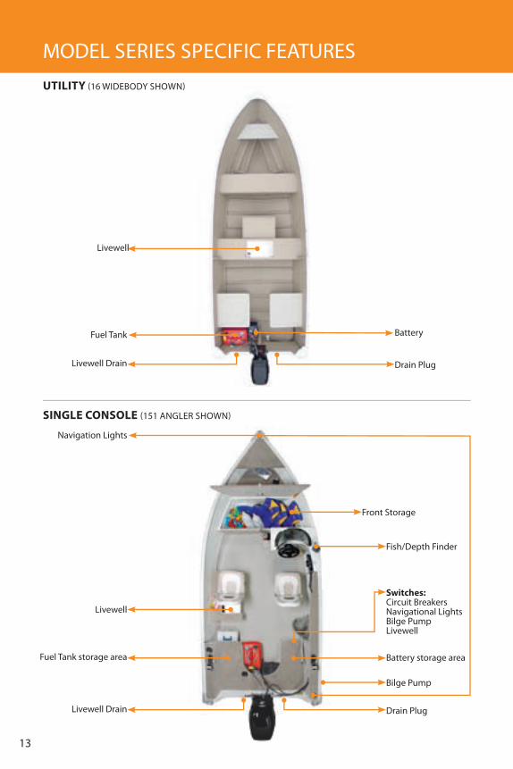
MODeL SerIeS SPeCIfIC feATureSutIlIty (16 wIDeBODy SHOwn)
sINgle coNsole (151 AngLer SHOwn)
Battery
Battery storage area
navigation Lights
Bilge Pump
Drain Plug
Drain Plug
Livewell
Livewell
fuel Tank storage area
Livewell Drain
Livewell Drain
fuel Tank
fish/Depth finder
front Storage
switches:Circuit Breakersnavigational LightsBilge PumpLivewell

14
poNtooN (LuXurA SHOwn)
Cranking Battery storage area
fuel Tank Vent
Deep Cycle Battery storage area
Bow Lights
Bow Docking Lights & nav Lights
Trolling motor plug-in
Bilge Pump
Drain Plug
Boarding Ladder
rear Livewell
glove Box
In-fl oor rod storage
Side storage
front Livewell
Built-In fuel Tank
fuel Tank storage areaBattery storage area
Change room & Sundeck
fuel Cap
Portable Ladder Anchors
Livewell Drain
fish/Depth finder
gauges
gauges
switches:Circuit Breakersnavigation LightsBilge PumpLivewellHorn
switches:Circuit Breakersnavigation LightsHorn12 volt outlet
full WINdshIeld (18 XCALIBur SHOwn)
Anchor Light
under Seat Storage

15
BOAT feATureSfeatures discussed in this section is standard or optional on some models and not available on others. See your dealer for more information.
trollINg motor operatIoN:
Battery:Deep cycle battery (trolling motor installation) is located in the bow of your boat and your cranking battery is located in the stern.
deep cycle Battery
deep cycle Battery
cranking Batterycranking
Battery
cranking Batterycranking
Battery
1.
1.
2. 3. 4.
2. 3. 4.
Pull up the release handle, hold the shaft and lift
the motor up.
The motor is ready to connect to the
power source
Loosen depth collar by turning the knob handle
and slide the depth collar to desired length
stowing your trolling motor:
deploying your trolling motor: Check that the motor is secured to the boat before deploying.
while lifting, rotate the shaft until the lower
unit is aligned with the locking cradle.
Pull up on the release handle and raise the
motor out of the stow position
Pull up on the release handle and raise the
motor out of the water
Hold the motor by the shaft and raise it into a
vertical position
Push down on the column to lock the cradle and to lock the release handle. Check that it is secure.

16
NavIgatIoNal lIghts:This two-position switch activates the bow and stern running navigation lights. when in the “up” or “nav” position, both the red/green bow light and white anchor light are on. when in the “down” or “Arc” position, just the white anchor light is on indicating that you are stationary or anchored in low light conditions.
sWItches
BIlge pump:The bilge pump switch may be used to turn the pump on or off. Only run the pump until it no longer expels water. do not run the bilge pump dry.
trollINg motor plug-IN:The trolling motor plug-in is located at the front of the boat.
utility models Pro Classic models gen X models
Select Pontoon models Deluxe Pontoon models

17
BOAT feATureS continued
horN:This switch activates the boat’s horn. Push the switch and hold it to sound the horn.
The livewell system on your boat is designed to supply the water and oxygen needed for the survival of your on-board fish. The following instructions will help you understand the livewell system that you have in your boat.
livewell operation:1. Install the removable Threaded Sure-Lock removable stand pipe in the drain fitting inside the livewell2. Turn the flow-adjustment tap counterclockwise in the livewell.3. Start the livewell filling pump using the livewell switch that corresponds to your boat. The water will rise in the livewell until it reaches the top of the overflow protection pipe.4. To control the aerator spray. use the flow-adjustment tap.5. Turn off the livewell pump once the livewell is full, and your are done.6. Turn pump on every few minutes to refresh water
Note: If equipped with a horn, you still require a manual sending device according to Canadian Coast guard regulations, such as a pealess whistle.
lIveWell:
lIveWell a:
a:
lIveWell B:
lIveWell c:
flow-adjustment tapAerator Aerator
Aeratorflow-adjustment tap
Overflow protection drain
Drain plug
Drain
Drain
Threaded Sure-Lock removable stand pipe with overflow protection
Threaded Sure-Lock removable stand pipe with overflow protection
Select Pontoon models Deluxe Pontoon models Select gen X models
B: c:

18
fIsh/depth fINder:All Lowrance sonars have an automatic mode that finds and displays the bottom, fish, underwater structure, water temp and more. read Lowrance manual for complete instructions. (to power on or off - hold button for 5 seconds)
cIrcuIt Breakers:If any issues arise, simply push the eZ reset circuit breaker. If it continues to “pop” notify your local Legend Dealer.
12 volt outlet:Be sure to to turn off all 12 volt outlet items before leaving the boat.
Note: not to be used as a cigaret lighter.
1. To open, simply unbutton the snap on the back of your seat and raise the back section.2. To remove the seat from the seat post, lift up the handle located on the right-hand side underneath the seat base and pull.3. To remove the seat post from the floor base, press the locking device at the bottom of the seat post, twist the seat post and pull upward.4. To turn your seat around, while sitting on it, lift up the handle located on the right hand side underneath the seat base and move your seat in either direction. 5. To slide your seat forward or backward, lift up the handle located on the front underneath your seat base and push or pull.6. To incline the back of your seat, lift up the swivel located on the left-hand side of the seat base and lean backward.(On deluxe captain’s chairs only)
Note: Be sure to lubricate all seat pedestals, seat and floor bases with a light silicone spray containing teflon. Due to the vents located on the bottom of the seats, they should not be stored upside down as they will fill with rain water.
Snap
Slider handle
Seat baseSeat base handle
Seat Post locking device
floor base
seat Bases:seats:your boat comes equipped with different models of pedestal seats. Depending on your boat model, your seats may not be equipped with all of the following adjustments.
Transducercenterline
water Temp
Transom
Digital depth
Hull bottom
Bottom signal
Surface signal
fish symbols
grayline
Depth range at bottom of depth scale
StructureVoltmeter

19
hoW to InSTALL A TrAVeL COVer
1. 2. 3. 4.
1. 2. 3. 4.
1. 2. 3. 4.
custom travel cover
BoW to sterN cover
custom cockpIt cover
Overlay cover inside your boat
Overlay cover inside your boat
Snap down bow. Leave middle windshield fl ap
unsnapped
windshield fl ap
Note: There are special anti-release snaps (Pull The Dot Snaps) installed at strategic intervals in your cover. These snaps prevent unwanted release while underway. To release them, simply roll from the front of the snap to the back while lifting up. roll from back to the front to put back on.
Snap down stern snaps
Snap down stern snaps
Snap down stern
Snap down bow snaps
Snap down bow snaps
Overlay cockpit cover and begin snapping all
windshield snaps
Snap down all remaining snaps
Snap down all remaining snaps
Snap down sides
Support barsmust be straight
Height adjustment threaded knob

20Note: not meant for use on roadways while trailering. Doing so may result in damage to top.
hoW to InSTALL A fuLL STAnD uP TOP
1.
5.
9.
2.
6.
10.
3.
7.
11.
4.
8.
12.
Lift Stand-up Top in boot position
unfold stand-up top
first, snap curtains to gunnel then zip into place
Pull back tubular stability bars and insert locking clip
into place
Snap down front windshield snaps and tighten tension strap
Zip rear enclosure until fully closed
unhook rear tubular stability bars
Pull front and middle tubular stability bars forward
(loosen tension strap)
Tension strap
Locate rear enclosure and snap all available rear snaps
unzip storage boot and stow
Locate Side aft curtains.
Pull back side bars in slider to tighten top.

21
WarraNty INformatIoN
pro classIc serIes WarraNtyeach Pro Classic model has a leakproof for life main seam hull warranty and an amazing 10 year warranty on most other hull components. This industry leading warranty is second to none for riveted boats.
geN x serIes WarraNtyevery Legend gen X model carries our exciting and industry leading Leakproof for Life warranty. It is remarkably simple. It covers the entire structure of the hull against leaks through the hull for as long as you own the boat. In fact it’s the kind of warranty you won’t find on any other aluminum boat. Ask your local Legend dealer for all of the details of our outstanding warranty.
poNtooN serIes WarraNtyLegend Pontoon boats are backed by a lifetime warranty on the tubes, decking and transom so you will be assured of hassle-free boating for years to come. your local Legend dealer can explain all of the details of our outstanding warranties.
addItIoNal WarraNty
legeNd product protectIoNLegend’s product protection can offer you up to 6 years of peace of mind boating by extending the warranty on your complete boat, motor and trailer package. from trolling motors to outboards, we’ve got you covered. eNgINe: All internal lubricated parts contained within the engine including: Pistons, Piston rings and Pins, Connecting rods, Connecting rod Bearings, Crankshaft, Crankshaft Main Bearings, Camshaft, Camshaft Bearings, Cam followers, Timing Chain or Belt, Timing Chain Cover, Timing gears, Timing guides and Tensioners, rocker Arms, rocker Shafts, Cylinder Head Valves, Valve guides, Valve Lifters, Valve Springs, Valve retainers, Valve Seals, Valve Covers, Oil Pump and Housing, Oil Pan (excluding Drain Plug Threads), Intake and exhaust Manifolds, engine Mounts, flywheel / flexplate (excluding Teeth), reeds Valves and reed Blocks Cage. Seals and gaskets in conjunction with a failure of a listed component only. Note: Cylinder Head(s), engine Block / Crankcase and Cylinder Barrels are covered only if damaged by the failure of an internally lubricated part.
loWer uNIt: All internal lubricated parts contained within the Lower unit Case including: gearcase Head, Bearing and Oil retainer, Driveshaft and upper Bearing, Shift rod and/or Cover Assembly, Pinion gear and Bearing, forward and reverse gears, Carrier Bearings, Shims, Thrust washers and Propeller Shaft, Seals and gaskets in conjunction with a failure of a listed component only. Note: Lower unit Housing is covered only if damaged by the failure of an internally lubricated part.

22
luBrIcatINg system: Complete Oil Injection System including: Oil Injection Check Valve, Injection Pump, Pump Drive gear, Pump Drive Shaft, Low Oil Level Sensor, Oil flow warning Sensors and Control Modules, Oil Tank reservoir, Tank (Oil) Cap, Tank Pickup Tube, Oil Level warning Horn and/or Light, Oil Lines, Complete Metering System. warning Module, remote Injection Tank, Seals and gaskets in conjunction with a failure of a listed component only.
Jet drIve: All internal lubricated parts contained within the Pump Housing, Seals and gaskets in conjunction with a failure of a listed component only. Note: Pump Housing is covered only if damaged by the failure of an internally lubricated part.
poWer trIm aNd tIlt: Spring, Sending unit, Oil Pump, Pump relief Valve, O-ring, Trim Cylinder, Tilt Cylinder, Hydraulic Pump, Manual release Valve, reverse Lock Valve, Solenoids, Power Tilt Motor and Power Trim Motor, Seals and gaskets in conjunction with a failure of a listed component only.
fuel system: fuel Delivery Pump, fuel Injection Pump, fuel Injector(s), fuel Distributors, flame Arrester, rails, fuel Tank, Metal fuel Lines and fittings, fuel Pressure regulator, wiring Harness, Seals and gaskets in conjunction with a failure of a listed component only.
electrIcal: Alternator, rectifier, Voltage regulator, Starter Motor, Starter Solenoid, Starter Drive, engine Mounted wiring Harness and Connectors, windshield wiper Motor, Power Pack / Switch Box, Distributor, Ignition Coil and Switch, engine Control Module, electronic Ignition Module / CDI, eCu/electronic fuel Injection Control Modules / Sensors, Limit and Control Switches, Trigger Coil and Stator, Stereo (factory or Dealer Installed Audio System – Speakers are excluded).
steerINg: Steering Control Helm Assembly, Steering Bracket and Bushing, Swivel Bracket and Bearing, Control rack and yoke Assembly, Power Steering Pump, Power Cylinder Assembly, Steering wheel and Coupling, Hub and Steering Cables, Seals and gaskets in conjunction with a failure of a listed component only.
coNtrols: Throttle Assembly, remote Control Starter/Choke Primer Switch, Starter/Stop Switch, Trim/Tilt Switch and Ignition Switch, Shift & Throttle Cables, Shift Control Box, Shift Interrupter Switch. Turbocharger / Supercharger (factory installed only) Turbocharger / Supercharger Housing (when damaged from within) and all internal lubricated parts including Turbine(s), Shaft, Bushings and waste gate Actuator, Seals and gaskets in conjunction with a failure of a listed component only.
sportsplus packageelectric Trolling Motor: All internal parts contained within the Motor Housing, wiring Harness, foot/Hand Speed Control, Steering Cable and gears, Bow Arm Bracket, Seals and gaskets in conjunction with a failure of a listed component only. Depth finder/fish finder: unit, wire Harness, Control Cable, Transducer. electrical Accessories: Bilge Pump, Bilge Blower, Live well Pump, Aerifier, Sea/Lake water Temperature gauge including Sensor and Control Cable, PH Meter, Battery Main Switch and Selector Switch, Isolator Switch, Tach Head, Voltage and All Pressure gauges, fuel gauge, Speedometer and Tilt/Trim gauge, remote Spotlight (manual control panel, horizontal/vertical control motors, light housing), Bow and Marker Lights, running Lights, Cockpit Lights,. electric Horn, Stereo: factory or Dealer Installed Audio System. Note: Speakers are excluded). Anchor / Control System: winch, electric windless Motor, Bow Pulpit guide, and Switches. System Monitors: fume detector Carbon Monoxide (CO), fuel Vapour, and High Bilge Level Sensor. Canvas Top: All Mechanical Components of Canvas Top System.
traIler package Master Cylinder, Hydraulic Brake Actuator, Backing Plates, Trailer frame welds, Suspension Springs, Spring Hanger Brackets and u-Bolts, Axles, Spindles, wheel Bearings, Hubs, roller Cradles (excluding rollers), Manual winch and Stand, Seals and gaskets in conjunction with a failure of a listed component only.
If you have any questions after reading this manual, please feel free to contact your local Legend dealer or call 1.800.461.4050
Thank you for choosing Legend!!

4805 RR 55, Whitefish, Ontario P0M 3E0 Phone: 705.866.2821 Fax: 705.866.2616Email: [email protected]
Legend is a division of
For your nearest dealer call the Legend Hotline 1.800.461.4050 or visit our website at www.legendboats.com