Embed Size (px)
Citation preview

Ozonator
O3
TB1
230 VAC, 3-Wire ConnectionUSE COPPER CONDUCTORS ONLY. WIRE SIZE MUST BE APPROPRIATE PER NEC AND/OR LOCAL CODES
21
Flow Switch
Hi-limit/Freeze Sensor
Temperature Sensor
J2
J3
F120A250VSC-20
Circ.Pump
MainPump
SpaLight
Transformer230 VAC
J4
HILO
GRN
Logic Jumper Settings
All Export 50 Hz Models:JP1 1-2 ON = 20A Logic*JP1 1-2 OFF = 30A Logic*Factory Jumper Setting
Temp. Jumper Settings (All Models):JP1 7-8 ON = Celsius Temp Display JP1 7-8 OFF = Fahrenheit Temp Display
BLU BRN
JP1
42
31
6 58 7
Heater Specifications• Export 50 Hz Model: 2.7 kW @ 230 VAC
J20
J21
J12
J14
J16
J11
J15
J13
J17 J7 J8 J9 J10
J5
J6
Heater IN Heater OUT
F1
K1
K2
K3
K4
K5 K7 K8
BLK
WHT
BRN
BRN
BLU
BLU
BLU
BRN
BRN
BLK BLU BRN BLU BRN
J1
Control Panel
LED Series Hot Tub Owner’s ManualJ-210, J-220, J-230 Models6530-322, Rev-C

Attention New Spa Owner!Congratulations on the purchase of your new Jacuzzi® spa! The following is a list of automated functions performed by your spa. These functions are listed below in an attempt to suppress any operational concerns you may have during the first 24-hours of ownership! Also listed below are important maintenance recommen-dations you should observe on a regular basis to protect your new investment.
Automated OperationsApproximately two minutes after power is applied to the spa, the first skimming/heating cycle turns on pump 1. In J-230 models, an automatic five minute “blow-out” function also activates pump 2 for a period of five minutes to flush all lines. Then, after five minutes, pump 2 turns off and pump 1 continues to operate for the duration of the cycle. Note: this function only occurs during the first filtration/heating cycle each day.
Maintain Healthy Spa WaterAlways maintain your spa’s water chemistry within the following parameters as defined by the Association of Pool And Spa Professionals/USA:
Always maintain your spas filter as outlined below to ensure healthy spa water. Refer to page 27 “Water Quality Maintenance” for additional information.
Required Filter MaintenanceYour new spa is equipped with an advanced water filtration system that provides unsurpassed water quality! To ensure maximum water quality at all times, you should clean the filter cartridge every three months, or earlier as necessary. See page 24 for detailed filter cartridge cleaning/replacement instructions.
Required Water ReplacementYou should replace the spa’s water every 3 months. The frequency depends on a number of variables including frequency of use, number of users, and attention paid to water quality maintenance. You will know it is time for a change when you cannot control sudsing and/or you can no longer get the normal feel or sparkle to the water, even though the key water balance measurements are all within the proper parameters. See page 27-28 for additional information.
pH 7.2 - 7.4Free Chlorine 3-5 ppmFree Bromine 4-6 ppmTotal Alkalinity 100-120 ppmCalcium Hardness 150-250 ppm

Table of Contents
1.0 Important Spa Owner Information ..............................................12.0 FCC Notice ....................................................................................13.0 Important Safety Instructions .....................................................2
4.0 Choosing A Location ...................................................................74.1 OutdoorLocation...........................................................................74.2 IndoorLocation..............................................................................8
5.0 General Electrical Safety Instructions .......................................86.0 Power Requirements ...................................................................97.0 Electrical Wiring Instructions ...................................................108.0 Spa Fill Up Procedure ...............................................................13
9.0 Control Functions ......................................................................179.1 ControlPanel...............................................................................179.2 SpaFeaturesAndControls..........................................................189.3 Jet/AirControlsDiagram(J-210&J-220Models).......................199.4 Jet/AirControlsDiagram(J-230Models).....................................20
10.0 Operating Instructions ..............................................................2110.1 SettingWaterTemperature..........................................................2110.2 ActivatePumps............................................................................2110.3 LightButton..................................................................................2110.4 SelectingDesiredMessageAction..............................................2210.5 AdjustingIndividualJetFlow.......................................................2210.6 AirControls..................................................................................22
11.0 Automatic Filtration Cycles ......................................................2211.1 StandardFiltration/HeatingModes(F1-F3).................................2211.2 EconomyFiltration/HeatingModes(F4-F6).................................2311.3 LockModes(L1-L2).....................................................................2311.4 SelectingTheSkimmer/HeatingMode........................................23
12.0 Spa Maintenance ........................................................................2412.1 CleaningTheFilter.......................................................................2412.2 DrainingandRefilling...................................................................2512.3 CleaningTheSpaInterior............................................................2512.4 PillowCare(J-220/J-230Only)....................................................2512.5 MaintainingTheCover.................................................................2612.6 MaintainingTheSyntheticCabinet..............................................2612.7 Winterizing...................................................................................2611.8 RestartingYourSpanColdWeather...........................................27

13.0 Water Quality Maintenance .......................................................2713.1 pHControl....................................................................................2713.2 Sanitizing......................................................................................2813.3 OptionalCDOzoneWaterMaintenanceSystem........................28
14.0 Error Conditions/Error Messages ............................................2814.1 PanelDisplaysSN1.....................................................................2814.2 PanelDisplaysSN2.....................................................................2914.3 PanelDisplaysFL1......................................................................2914.4 PanelDisplaysFL2......................................................................2914.5 PanelDisplaysCOL.....................................................................2914.6 PanelDisplaysICE......................................................................2914.7 PanelDisplaysOH.......................................................................2914.8 PanelDisplays----...................................................................29
15.0 Troubleshooting Procedures ....................................................3015.1 NoneofTheComponentsOperate(e.g.Pump,Light)................3015.2 PumpDoesNotOperateButLightDoes.....................................3015.3 PoorJetAction.............................................................................3015.4 WaterisTooHot..........................................................................3015.5 NoHeat........................................................................................31
16.0 J-210/J-220 Convertible Circuit Diagram (60Hz) .....................3217.0 J-230 Circuit Diagram (60Hz) ....................................................3318.0 J-220 Export Circuit Diagram (50Hz) ........................................3419.0 J-230 Export Circuit Diagram (50Hz) ........................................35
page �
1.0 Important Spa Owner InformationYour Jacuzzi® 200 series spa is constructed to the highest standards and is capable of providing many years of trouble-free use. However, because heat retentive materials are utilized to insulate the spa for effi-cient operation, an uncovered spa surface directly exposed to sunlight and high temperatures for an extended period is subject to permanent damage. Damage caused by exposing the spa to this abuse is not covered by warranty. We recommend that you always keep the spa full of water when it is exposed to direct sunlight and that you keep the Jacuzzi premium insulating cover in place at all times when the spa is not in use. Read and carefully follow the requirements for your spa’s support base found in section 4.0 titled, “Choosing a Location” (page 7).
Jacuzzi constantly strives to offer the finest spas available, there-fore modifications and enhancements may be made which affect the specifications, illustrations and/or instructions contained herein.
2.0 FCC NoticeThis equipment has been tested and found to comply with the limits for a Class B Digital Device, pursuant to Part �5 of the FCC Rules. These limits are designed to provide reasonable protection against harmful interference in a residential installation. This equipment generates, uses and can radiate radio frequency energy and, if not installed and used in accordance with the instructions, may cause harmful interference to radio communications. However, there is no guarantee that interference will not occur in a particular installation. If this equipment does cause harmful interference to radio or television reception, which can be deter-mined by turning the equipment off and on, the user is encouraged to try to correct the interference by one or more of the following measures:
�. Rearrange or relocate the receiving antenna.2. Increase the separation between the equipment and receiver3. Connect the equipment into an outlet on a circuit different from the
circuit connected.4. Consult the dealer or an experienced radio/TV technician for help.
Changes or modifications not expressly approved by the party responsible for FCC compliance could void the user’s authority to operate this equipment.

page 2
3.0 IMPORTANT SAFETY INSTRUCTIONS
READ AND FOLLOW ALL INSTRUCTIONS CAREFULLYWhen installing and using this electrical equipment, basic safety precau-tions should always be followed, including:
�. WARNINg: To reduce the risk of injury, do not permit children to use this product unless they are closely supervised at all times.
2. WARNINg: A grounding wire connector is provided on this unit to connect a minimum No. 8 AWG (8.4mm2) solid copper conduc-tor between this unit and any metal equipment, metal enclosures of electrical equipment, metal water pipe, or conduit within 5 feet (�.5m) of the unit.
3. DANgER: Risk of Accidental Drowning. Extreme caution must be exercised to prevent unauthorized access by children. To avoid accidents, ensure that children cannot use this spa unless they are supervised at all times.
4. DANgER: Risk of Injury. The suction fittings in this spa are sized to match the specific water flow created by the pump. Should the need arise to replace the suction fittings or the pump, be sure that the flow rates are compatible. Never operate the spa if the suction fit-tings are broken or missing. Never replace a suction fitting with one rated less than the flow rate marked on the original suction fitting.
5. DANgER: Risk of Electric Shock. Install at least 5 feet (�.5m), from all metal surfaces. As an alternative, a spa may be installed within 5 feet of metal surfaces if each metal surface is permanently con-nected (bonded) by a minimum No. 8 AWG (8.4 mm2) solid copper conductor attached to the wire connector on the grounding lug, inside the equipment compartment on the equipment box.
6. DANgER: Risk of Electric Shock. Do not permit any electrical appli-ance, such as a light, telephone, radio, television, etc. within 5 feet (�.5m) of a spa unless such appliances are built-in by the manufac-turer.
7. ELECTRICAL SUPPLY: The electrical supply for this product must include a suitably rated switch or circuit breaker to open all ungrounded supply conductors to comply with section 422-20 of the National Electrical Code/USA, ANSI/NFPA 70. The disconnect must be readily accessible and visible to the spa occupant but installed at least 5 feet (�.5m), from the spa water.

page 3
8. WARNINg: To Reduce the Risk of Injury:
9. The water in the spa should never exceed �04°F (40°C). Water temperatures between �00°F (38°C) and �04°F (40°C) are consid-ered safe for a healthy adult. Lower water temperatures are recom-mended for young children and when spa use may exceed �0 min-utes.
�0. Since excessive water temperatures have a high potential for caus-ing fetal damage during the early months of pregnancy, pregnant or possibly pregnant women should limit spa water temperatures to
�00°F (38°C). If pregnant, please consult your physician before using a spa.
��. Before entering the spa, the user should measure the water temperature with an accurate thermometer since the tolerance of
water temperature-regulating devices may vary as much as +/- 5°F (2°C).
�2. The use of alcohol, drugs, or medication before or during spa use may lead to unconsciousness with the possibility of drowning.
�3. Persons suffering from obesity or a medical history of heart disease, low or high blood pressure, circulatory system problems, diabetes, infectious diseases or immune deficiency syndromes should consult a physician before using a spa. If you experience breathing difficul-ties in association with using or operating your spa, discontinue use and consult your physician.
�4. Persons using medication should consult a physician before using a spa since some medication may induce drowsiness, while other medication may affect heart rate, blood pressure, and circulation.
�5. Always shower before and after using your spa. To reduce the pos-sibility of contracting a waterborne illness, always maintain water chemistry within the parameters listed on the inside cover of this manual. If you or other bathers experience such a condition, dis-continue use and seek medical attention.

page 4
IMPORTANT CSA SAFETY INSTRUCTIONS (CANADA ONLY)When using this electrical equipment, basic safety precautions should always be followed, including the following:
�. READ AND FoLLoW ALL INSTRUCTIoNS.
2. A green colored terminal or a terminal marked G, Gr, Ground, Grounding or the symbol* is located inside the supply terminal
box or compartment. To reduce the risk of electric shock, this terminal must be connected to the grounding means provided in the
electric supply service panel with a continuous copper wire equiva-lent in size to the circuit conductors that supply this equipment.
*IEC Publication 4�7, Symbol 50�9.
3. At least two lugs marked “Bonding Lugs” are provided on the exter-nal surface or on the inside of the supply terminal box/compartment. To reduce the risk of electric shock, connect the local common bonding grid in the area of the spa to these terminals with an insu-lated or bare copper conductor not smaller than No. 6 AWG (�0 mm2).
4. All field installed metal components such as rails, ladders, drains or other similar hardware within �0 feet (3m) of the spa shall be bonded to the equipment grounding buss with copper conductors not smaller than No. 6 AWG (�0 mm2).
5. SAVE THESE INSTRUCTIONS.
WARNINg: Children should not use spas without adult supervision.
WARNINg: Do not use spas unless all suction guards are installed to prevent body and hair entrapment.
WARNINg: People with infectious diseases should not use a spa.
WARNINg: To avoid injury, exercise care when entering or exiting the spa.
WARNINg: Do not use drugs or alcohol before or during the use of a spa to avoid unconsciousness and possible drowning.
WARNINg: Pregnant or possibly pregnant women should consult a physician before using a spa.
page 5
WARNINg: Water temperature in excess of 40°C (�04°F) may be injuri-ous to your health.
WARNINg: Before entering the spa, measure the water temperature with an accurate thermometer.
WARNINg: Do not use a spa immediately following strenuous exercise.
WARNINg: Prolonged immersion in a spa may be injurious to your health.
WARNINg: Do not permit electric appliances (such as lights, telephone, radio, television, etc.) within 5 feet (�.5m) of this spa unless such appli-ances are built-in by the manufacturer.
CAUTION: Maintain water chemistry in accordance with manufacturer’s instructions.
WARNINg: The use of alcohol or drugs can greatly increase the risk of fatal hyperthermia in spas.
SAVE THESE INSTRUCTIONS
HYPERTHERMIAProlonged immersion in hot water may induce hyperthermia. A descrip-tion of the causes, symptoms, and effects of hyperthermia are as fol-lows:
Hyperthermia occurs when the internal temperature of the body reaches a level several degrees above the normal body temperature of 98.6°F (37°C). The symptoms of hyperthermia include drowsiness, lethargy, and an increase in the internal temperature of the body. The effects of hyperthermia include:
�. Unawareness of impending hazard;
2. Failure to perceive heat;
3. Failure to recognize the need to exit spa;
4. Physical inability to exit spa;
5. Fetal damage in pregnant women; and
6. Unconsciousness and danger of drowning.

page 6
A warning sign is provided in your warranty packet. Please install it at a location near your spa, where it is visible to the user of the spa. For additional or replacement signs please contact your local Jacuzzi spas dealer and reference item num-ber #6530-082.
CAUTIONS�. Persons suffering from heart disease, diabetes, high or low blood
pressure, and any condition requiring medical treatment, pregnant women, the elderly, or infants should consult with a physician before using a spa.
2. The Consumer Products Safety Commission/USA has stated that the water temperature in a spa should not exceed �04°F (40°C). Immersion in water in excess of �04°F (40°C) can be hazardous to your health.
3. observe a reasonable time limit when using the spa. Long expo-sures at higher temperatures can cause high body temperature. Symptoms may include dizziness, nausea, fainting, drowsiness, and reduced awareness. These effects could possibly result in drown-ing.
4. Do not use the spa under the influence of alcohol, narcotics, or other drugs. Use of the spa under these conditions may lead to seri-ous consequences.
5. Always test the spa water temperature before entering the spa. Enter and exit the spa slowly. Wet surfaces can be very slippery.
6. Never bring any electrical appliances into or near the spa. Never operate any electrical appliances from inside the spa or when you are wet unless such appliances are built-in by the manufacturer.
7. Proper chemical maintenance of spa water is necessary to maintain safe water and prevent possible damage to spa compo-
nents.
8. Use the straps and clip tie downs to secure the cover when not in use. This will help to discourage unsupervised children from enter-ing the spa and keep the spa cover secure in high-wind conditions. There is no representation that the cover, clip tie-downs, or actual locks will prevent access to the spa.

page 7
4.0 Choosing A LocationIMPORTANT: Because of the combined weight of the spa, water and users, it is extremely important that the base upon which the spa rests be smooth, flat, level and capable of uniformly supporting this weight, without shifting or settling, for the entire time the spa is in place. If the spa is placed on a surface which does not meet these requirements, damage to the skirt and/or the spa shell may result. Damage caused by improper support is not covered under warranty. It is the responsibility of the spa owner to assure the integrity of the support over time.
We recommend a poured, reinforced concrete slab with a minimum thickness of 4 inches (�0cm). Wood decking is also acceptable provided it is constructed so that it meets the requirements outlined above. The spa must be installed in such a manner as to provide drainage away from the spa. Placing the spa in a depression without provisions for proper drainage could allow rain, overflow and other casual water to flood the equipment and create a wet condition in which it would sit. For spas which will be recessed into a floor or deck, install so as to permit access to the equipment, either from above or below, for servicing. Make certain that there are no obstructions which would prevent removal of the cabinet side panels and access to the jets components, especially on the side with the equipment bay doors.
4.1 Outdoor LocationIn selecting the ideal outdoor location for your spa, we suggest that you take into consideration:
�. The proximity to changing area and shelter (especially in colder weather).
2. The pathway to and from your spa (this should be free of debris so that dirt and leaves are not easily tracked into the spa).
3. The closeness to trees and shrubbery (remember that leaves and birds could create extra work in keeping the spa clean).
4. A sheltered environment (less wind and weather exposure can result in lowered operation and maintenance costs).
5. The overall enhancement of your environment. It is preferable not to place the spa under an unguttered roof overhang since run-off water will shorten the life expectancy of the spa cover.

page 8
4.2 Indoor LocationFor indoor installations, be certain to make provisions for proper ventilation. When the spa is in use, considerable amounts of moisture will escape. This can damage certain surfaces over time. If you have any questions regarding the placement or installation of your spa, consult your authorized Jacuzzi dealer.
WARNINg: In addition to maintenance of filters and water chemistry, proper ventilation is recommended to reduce the risk of exposure to viruses and bacteria that could be present in the air or water. Consult a licensed architect or building contractor to determine your specific needs if installing your spa indoors.
5.0 gENERAL ELECTRICAL SAFETY INSTRUCTIONSYour new Jacuzzi® spa is equipped with a “state-of-the-art” equipment system. It contains the most advanced safety and self-protective equip-ment in the industry. Nonetheless, this spa must be installed properly to insure dependable usage. Please contact your dealer or local building department should you have any questions regarding your installation.
Proper grounding is extremely important. Jacuzzi spas are equipped with a current collector system. A pressure wire connector is provided on the surface of the control box, located outside the equipment door (Figure B, page �2) to permit connection of a bonding wire between this point and any ground metal equipment, metal water pipe or conduit within 5 feet (�.5m) of the spa, or copper clad grounding rod buried within 5 feet (�.5m) of the spa. Bonding wire must be at least No. 8 AWG (8.4mm2) solid copper wire. This is a most important safety assur-ance feature. Before installing this spa, check with the local building department to insure installation conforms to local building codes.
120/240 Volt Convertible ModelsA spa connected to a �20VAC electrical service must be located close enough to a grounded, grounding-type electrical outlet so that the included power cord can be plugged directly into it. Do NoT USE AN EXTENSIoN CoRD as this could cause damage to the spa’s equipment due to insufficient voltage. The power supplied to this spa must be a dedicated circuit with no other appliances or lights sharing the power provided by the circuit.

page �
6.0 Power RequirementsJacuzzi® spas are designed to provide optimum performance and flex-ibility of use when connected to the maximum electrical service listed in the tables below. If you prefer, your dealer can perform a minor circuit board modification to allow your spa to accept an electrical service other than the factory setting.
US / Canada J-230 2-Pump Model (60Hz)
240V/40A* 240V/50A** 240V/60A***Voltage: 240 VAC 240 VAC 240 VAC# of Wires: 3 3 3Frequency: 60Hz 60Hz 60HzCurrent Draw: 26A 36A 45A Circuit Breaker: 40A, 2-Pole 50A, 2-Pole 60A, 2-Pole
* In 40A configuration, the heater will not operate while either jets
pump is running in high speed. Note: pump 2 runs only in high speed.** In 50A configuration, the heater will not operate while both jet pumps
are running in high speed. Note: pump 2 runs only in high speed. This is the factory setting.
*** In 60A configuration, the heater will operate while both jet pumps are running in high speed. Note: pump 2 runs only in high speed.
US/Canada J-210/J-220 1-Pump Convertible Model (60Hz)
120V/15A* 240V/30A* 240V/40A**Voltage: 120 VAC 240 VAC 240 VAC# of Wires: 3 (15A GFCI Cord 4 4 US only*)Frequency: 60Hz 60Hz 60HzCurrent Draw: 12A 21A 30A Circuit Breaker: 15A, 1-Pole 30A, 2-Pole 40A, 2-Pole
For 240 VAC Heater Operation: Move the red wire on the main terminal strip (TB1) from position #1 to position #3. Make certain wires are con-nected exactly as shown in Figure-D (page 12) before applying power. Failure to do so will result in damage to the circuit board and/or related components and void the manufacturer’s warranty.
*All Canadian spas must be hard wired (120 VAC or 240 VAC) per CSA Canadian standards. (page 4).
* In 15A/30A configuration, the heater will not operate at the same time as the high-speed jets pump. The factory setting is 120V/15A.
** In 40A configuration, remove the jumper JP1 #1-2 on the circuit board to allow the heater to operate at the same time as the
high-speed jets pump (page 32).
page 10
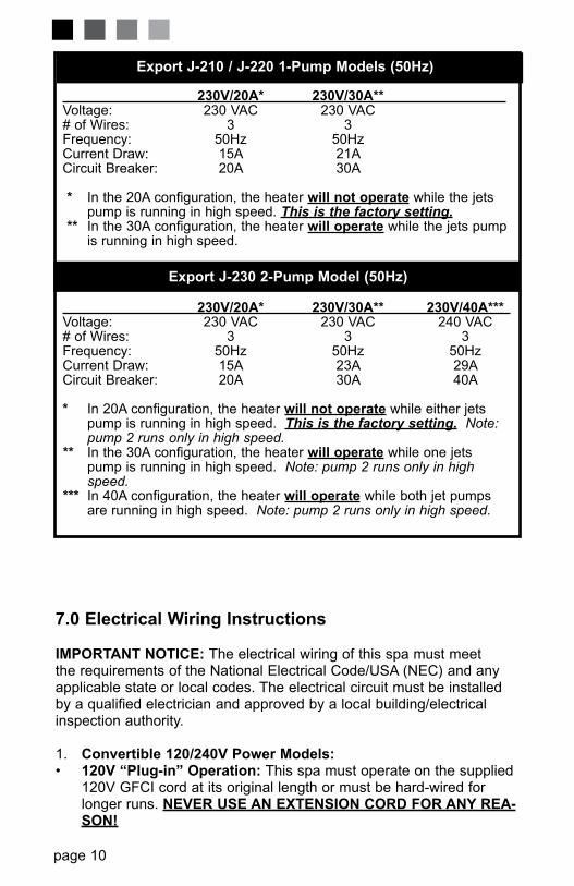
7.0 Electrical Wiring Instructions
IMPORTANT NOTICE: The electrical wiring of this spa must meet the requirements of the National Electrical Code/USA (NEC) and any applicable state or local codes. The electrical circuit must be installed by a qualified electrician and approved by a local building/electrical inspection authority.
1. Convertible 120/240V Power Models:• 120V “Plug-in” Operation: This spa must operate on the supplied
120V GFCI cord at its original length or must be hard-wired for longer runs. NEVER USE AN ExTENSION CORd FOR ANy REA-SON!
Export J-210 / J-220 1-Pump Models (50Hz)
230V/20A* 230V/30A** Voltage: 230 VAC 230 VAC # of Wires: 3 3 Frequency: 50Hz 50Hz Current Draw: 15A 21A Circuit Breaker: 20A 30A
* In the 20A configuration, the heater will not operate while the jets pump is running in high speed. This is the factory setting.** In the 30A configuration, the heater will operate while the jets pump is running in high speed.
Export J-230 2-Pump Model (50Hz)
230V/20A* 230V/30A** 230V/40A*** Voltage: 230 VAC 230 VAC 240 VAC # of Wires: 3 3 3 Frequency: 50Hz 50Hz 50HzCurrent Draw: 15A 23A 2�A Circuit Breaker: 20A 30A 40A
* In 20A configuration, the heater will not operate while either jets pump is running in high speed. This is the factory setting. Note: pump 2 runs only in high speed. ** In the 30A configuration, the heater will operate while one jets pump is running in high speed. Note: pump 2 runs only in high speed. *** In 40A configuration, the heater will operate while both jet pumps are running in high speed. Note: pump 2 runs only in high speed.

page 11
• Convertible 120/240V Operation: The included 120V GFCI cord must be discarded for 240V operation. This spa must be hard wired. Supplying power to either configuration above which is not in accor-dance with these instructions will void both the independent testing agency listing and the manufacturer’s warranty.
2. dedicated 230-240V Power Models: This spa must be permanently connected (hard-wired) to the power supply. NO
PlUg-IN CONNECTIONS OR ExTENSION CORdS ARE TO bE USEd IN CONJUNCTION WITH THE OPERATION OF THIS SPA. Supplying power to the spa which is not in accordance with these instructions will void both the independent testing agency listing and the manufacturer’s warranty.
3. The power supplied to this spa must be a dedicated circuit with no other appliances or lights sharing the power provided by the circuit.
4. To determine the current, voltage and wire size required, refer to section 6.0 “Power Requirements” (page �-10).
• Wire size must be appropriate per NEC/USA and/or local codes.• We recommend type THHN wire.• All wiring must be copper to ensure proper connections. do not
use aluminum wire.• When using wire larger than #6 (10mm2), add a junction box near
the spa and reduce to short lengths of #6 (10mm2) wire to connect to the spa.
5. The electrical supply for this product must include a suitably rated switch or circuit breaker to open all ungrounded supply conductors to comply with Section 422-20 of the National Electrical Code/USA, ANSI/NFPA 70. The disconnecting means must be readily acces-sible to the spa’s occupant but installed at least 5 feet (1.5m) from spa water.
6. The electrical circuit supplied for the spa must include a suitable ground fault circuit interrupter (GFCI) as required by NEC/USA Article 680-42.
7. To gain access to the spa’s power terminal block, remove the screws securing the synthetic cabinet panel under the control panel (page 18). Then remove the four control box door screws and door (Figure B, page 12).
8. Select the power supply inlet you want to use (Figure A, page 12). Feed power cable to control box, then install it through the large opening provided in the bottom side of the box.
�. Connect wires, color to color, on terminal blocks TB1 and TB3 (Figures C-F, page 12-13). TIGHTEN SECURELY! All wires must be hooked up securely or damage could result.
10. Install control box door and screws and reinstall the cabinet side panels.
page �2
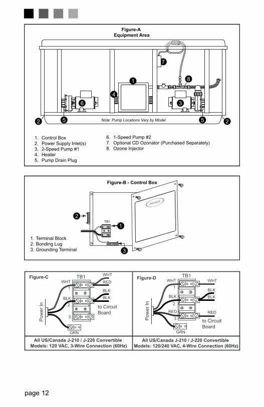
Figure-b - Control box
�. Terminal Block 2. Bonding Lug 3. Grounding Terminal
TB�
3
2
�
7
8
3 6
2 2
Figure-A Equipment Area
�. Control Box2. Power Supply Inlet(s)3. 2-Speed Pump #�4. Heater5. Pump Drain Plug
6. �-Speed Pump #2 7. optional CD ozonator (Purchased Separately) 8. ozone Injector
Flow
Note: Pump Locations Vary by Model5 5
�
4
BLUE
BLUE
BRoWN
BRoWN
�
2
US/Canada J-230 Models: 240 VAC, 3-Wire Connection (60Hz)
Figure-F TB�
All Export J-210 / J-220 / J-230 Models:230 VAC, 3-Wire (50Hz)
to Circuit Board
BLK
RED
Pow
er In
RED
RED
BLK
BLK
�
2
Figure-E TB�
to Circuit Board
Pow
er In
Green
TB3
Green
TB3
GRN
WHT
WHT
BLK
BLK
BLK
RED
�
2
3
Figure-C TB�
to Circuit Board
Pow
er In
GRN
WHT WHT
BLK
BLK
BLK
RED RED
�
2
3
All US/Canada J-210 / J-220 Convertible Models: 120/240 VAC, 4-Wire Connection (60Hz)
Figure-D TB�
to Circuit Board
Pow
er In
All US/Canada J-210 / J-220 Convertible Models: 120 VAC, 3-Wire Connection (60Hz)

page �3
Congratulations! You are now all set to get your new spa ready to use. Simply follow this step-by-step procedure below, before long, you will be enjoying your first glorious experience in your Jacuzzi J-200 spa.
8.0 Spa Fill Up ProcedureFoR BEST RESULTS, read each step in its entirety before proceeding with that step:
1. Prepare The Spa For Filling• Clear all debris from the spa. (Although the spa shell has been
polished at the factory, you may want to treat it with a specially for-mulated spa cleaner. Consult your authorized Jacuzzi dealer for additional information prior to filling spa.
• Remove filter lid then remove filter cartridge from filter bucket.
2. Fill Spa• Place the end of your garden hose into the empty filter bucket.
CAUTION: Never fill with water from a water softener. If your water is extremely “hard”, it is preferable to fill half-way with hard water and the rest of the way with softened water. or, you may fill entirely with hard water if you use a special water addi-tive available from your authorized Jacuzzi dealer.
• Fill spa until water covers all jets but does not touch the bottom of the lowest headrest. Do NoT oVERFILL.
IMPORTANT: Always fill your spa through the filter bucket after drain-ing. Failure to do so may cause air to be trapped in either pump, preventing the pump from circulating water. Remove the hose and replace the filter cartridge.
BLUE
BLUE
BRoWN
BRoWN
�
2
US/Canada J-230 Models: 240 VAC, 3-Wire Connection (60Hz)
Figure-F TB�
All Export J-210 / J-220 / J-230 Models:230 VAC, 3-Wire (50Hz)
to Circuit Board
BLK
RED
Pow
er In
RED
RED
BLK
BLK
�
2
Figure-E TB�
to Circuit Board
Pow
er In
Green
TB3
Green
TB3
GRN
WHT
WHT
BLK
BLK
BLK
RED
�
2
3
Figure-C TB�
to Circuit Board
Pow
er In
GRN
WHT WHT
BLK
BLK
BLK
RED RED
�
2
3
All US/Canada J-210 / J-220 Convertible Models: 120/240 VAC, 4-Wire Connection (60Hz)
Figure-D TB�
to Circuit Board
Pow
er In
All US/Canada J-210 / J-220 Convertible Models: 120 VAC, 3-Wire Connection (60Hz)

page �4
3. Turn On Power Turn on power to spa at the home’s circuit breaker. The heater and
filter/circulation pump will automatically activate. If the control panel LCD flashes water temperature and “COL” or “ICE”, refer to page 29 for additional information.
4. Activate Jets Pump 1 Depress the JETS � button on the control panel once to activate
jets pump #�.
5. Add Start-Up Chemicals Add the spa water chemicals as recommended by your authorized
Jacuzzi dealer. See section �3.0 “Water Quality Maintenance” (page 27) for general guidance.
6. Establish A Stable Sanitizer Reading Establish a stable sanitizer reading between 3 ppm and 5 ppm. To
ensure healthy water conditions, always maintain a constant sani-tizer reading within the levels recommended by the Association of Pool And Spa Professionals/USA printed on the inside cover of this manual. If sanitizer levels cannot be stabilized, perform the decon-tamination procedure steps 9-�5 on page �5-�6. Note: the “decon-tamination procedure” steps 9-15 should also be used after the spa has been “Winterized” (section 12.7, page 26 ) or has been sitting without power for an extended period.
7. Set Spa To Heat To warm spa water to a comfortable temperature, follow these
steps:• The LCD display on the control panel displays the actual tempera-
ture of the spa water. Press either the COOLER (-) or WARMER (+) button once to display the “set” temperature for 5 seconds. If you want the water to heat to a different temperature, simply press COOLER (-) or WARMER (+) within 5 seconds. The set tempera-ture increases or decreases by one degree each time one of these buttons is pressed.
• The heater will turn off when the temperature corresponding to the thermostat setting is achieved.
Important Heater Details:• The maximum water temperature setting for your spa is �04°F
(40°C) and the minimum setting is 80°F (27°C). • Setting the thermostat at maximum will not accelerate the heating process. This will only result in a higher ultimate temperature.
page �5
• The heater operates until the water reaches the programmed “set temperature”, then turns off. The heater will reactivate after the water cools to approximately �.5° below the set temperature.
8. Place Cover On Spa• Keeping the insulating cover in place anytime the spa is not in use
will reduce the time required for heating, thereby minimizing operat-ing costs.
• The time required for initial heat-up will vary depending on the start-ing water temperature.
DANgER: Risk of injury, always check water temperature carefully before entering spa!
Decontamination Procedure (Steps 9-15)Steps 9-�5 pages �5-�6 are only required when sanitizer levels are unstable after performing steps �-6 above. Disregard steps 9-�5 below if sanitizer levels remain stable at 3 ppm to 5 ppm after performing steps �-6.
9. Add 2.5 ounces of sodium dichlor for every �00 gallons of water. Refer to the table below for approximate water fill volume by model.
CAUTION: Never add chlorine tablets (trichlor) to your spa for any rea-son! This chemical may damage your spa and void the manufacturer warranty.
Water Fill Volume by ModelSpa Model Approximate Fill Volume
J2�0 .......................................220 US Gallons (833 Liters)J220 .......................................335 US Gallons (�,268 Liters)J230 .......................................340 US Gallons (�,287 Liters)
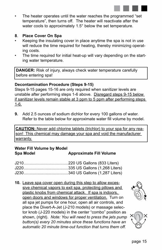
10. Leave spa cover open during this step to allow exces-sive chemical vapors to exit spa, protecting pillows and plastic knobs from chemical attack. If spa is indoors, open doors and windows for proper ventilation. Turn on all spa jet pumps for one hour, open all air controls, and place the Divert-A-Jet (J-2�0 models) or massage selec-tor knob (J-220 models) in the center “combo” position as shown, (right). Note: You will need to press the jets pump button(s) every 20 minutes since these functions have an automatic 20 minute time-out function that turns them off.
b

page �6
CAUTION: never leave your spa unattended for any reason while the cover is open and accessible to small children and animals!
11. Turn off power to the spa at the circuit breaker, then drain spa as outlined in section 12.2 “Draining And Refilling” (page 25).
12. Fill spa until water covers all jets but does not touch the bottom of the lowest headrest. Do NoT oVERFILL.
CAUTION: Never fill with water from a water softener. If your water is extremely “hard”, it is preferable to fill half-way with hard water and the rest of the way with softened water. or, you may fill entirely with hard water if you use a special water addi-tive available from your authorized Jacuzzi dealer.
13. Consult your authorized Jacuzzi dealer for chemical recommenda-tions, then add chemicals to spa water to achieve a constant sani-tizer reading within the levels recommended by the Association of Pool And Spa Professionals/USA printed on the inside cover of this manual.
14. Turn on all jet(s) pumps when adding chemicals to ensure proper mixing and leave your spa cover open until the sanitizer level falls below 5 ppm to protect pillows and plastic knobs from chemical
attack.
CAUTION: Never leave your spa unattended for any reason while the cover is open and accessible to small children and animals.
CAUTION: To prevent the unlikely possibility of contracting a waterborne illness, maintain water chemistry within step 6 pa-rameters. If you or other bathers experience such a condition, discontinue use and seek medical attention.
15. Establish a sanitizer reading between 3 ppm and 5 ppm, then allow the spa to set undisturbed for 8 hours. Retest water after 8 hours to determine if sanitizer levels are stable. If sanitizer levels are stable, your spa is ready for use. To ensure healthy water conditions, always maintain a constant sanitizer reading within the levels recommended by the Association of Pool And Spa Professionals/USA printed on the inside cover of this manual. If sanitizer levels are not stable at this time, it will be necessary to repeat this procedure in its entirety (steps �-�5) until stable sanitizer readings are achieved.

page �7
9.0 Control Functions
9.1 Control PanelA. LED Display: Can
display current water temperature (default dis-play), water temperature set point, selected skim-ming/heating mode, and error messages.
B. Warmer ( + ) Button: Increases water temperature set point.
C. Cooler ( - ) Button: Decreases water temperature set point.
D. Light Button: Turns underwater light on and off.
E. Jets � Button: Turns jets pump #� on and off. Press once for low speed; press a second time for high speed; press a third time to turn pump off.
F. Jets 2 Button (J-230 Models): Turns high-speed jets pump #2 on and off. Press once to turn pump #2 on; press a second time to turn pump #2 off.
G. Heat Indicator: Lit when heater is on.
Operation Details• Temperature Adjustment: 80 to �04°F (27 to 40°C). Factory default
setting is �00°F (38°C).
• Underwater Light operation: Light runs for � hour then shuts off for increased bulb life.
• Jets �/Jets 2 Button operation: Jets run for 20 minutes when acti-vated, then turn off automatically to conserve energy. Simply press either jets button to continue operation for an additional 20 minutes.
gA
b CD
E
F

page �8
9.2 Spa Features And Controls
1
4
2
2
4
4
7
5
9
8
10
3
�. Control Panel2. Air Controls3. Filter/Skimmer4. Therapy Jets5. Massage Selector (J-220 only). J-2�0 models use a “Divert-A-Jet”
which functions as a diverter in these models. See page �9 for details.
6. Therapy Seats
7. Spa Light 8. Vertical Jets (Foot Jets)9. Footwell Suction Fitting & Filter.�0. Heater Return/Gravity Drain
Fitting��. Calf Jets (J-220 only)
J-220 model illustrated - Location of Features Vary by Model
4

page �9
9.3 Jet/Air Controls Diagram(J-210 & J-220 Models)

page 20
9.4 Jet/Air Controls Diagram(J-230 Models)
page 2�
10.0 Operating InstructionsThe spa control system has automatic functions that operate upon start-up and normal operation to protect the system. Upon power up, the readout displays the following information:
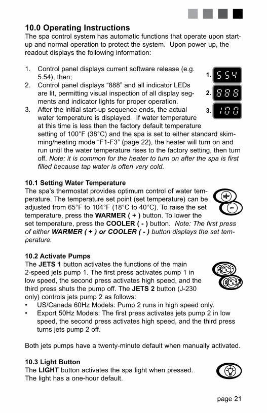
�. Control panel displays current software release (e.g. 5.54), then;
2. Control panel displays “888” and all indicator LEDs are lit, permitting visual inspection of all display seg-ments and indicator lights for proper operation.
3. After the initial start-up sequence ends, the actual water temperature is displayed. If water temperature at this time is less then the factory default temperature setting of �00°F (38°C) and the spa is set to either standard skim-ming/heating mode “F�-F3” (page 22), the heater will turn on and run until the water temperature rises to the factory setting, then turn off. Note: it is common for the heater to turn on after the spa is first filled because tap water is often very cold.
10.1 Setting Water Temperature The spa’s thermostat provides optimum control of water tem-perature. The temperature set point (set temperature) can be adjusted from 65°F to �04°F (�8°C to 40°C). To raise the set temperature, press the WARMER ( + ) button. To lower the set temperature, press the COOLER ( - ) button. Note: The first press of either WARMER ( + ) or COOLER ( - ) button displays the set tem-perature.
10.2 Activate PumpsThe JETS 1 button activates the functions of the main 2-speed jets pump �. The first press activates pump � in low speed, the second press activates high speed, and the third press shuts the pump off. The JETS 2 button (J-230 only) controls jets pump 2 as follows:• US/Canada 60Hz Models: Pump 2 runs in high speed only.• Export 50Hz Models: The first press activates jets pump 2 in low
speed, the second press activates high speed, and the third press turns jets pump 2 off.
Both jets pumps have a twenty-minute default when manually activated.
10.3 Light buttonThe LIgHT button activates the spa light when pressed. The light has a one-hour default.
1.
2.
3.

page 22
10.4 Selecting Desired Massage Action (J-210 & J-220 Only)Your Jacuzzi spa incorporates a “Divert-A-Jet” or “Massage Selector” (page �9) that allows you to custom-ize massage performance between various jet systems by diverting water between them. Simply turn the Divert-A-Jet or Massage Selector to position A (Combo), B, or C to divert water pressure to various jet groups. Note: The valve is intended to operate in positions A (Combo), B, and C for optimum performance. It is considered normal for sound levels within the valve to vary between positions due to the large amounts of water flowing through it! For optimum filtration benefits, leave the valve in position A (center position) when spa is covered. Select position B or C for maximum jet perfor-mance during spa use.
10.5 Adjusting Individual Jet FlowThe water flow to the individual jets in your spa can be increased or decreased by rotating the outside jet face. Note: Always keep at least 6 adjustable jets open at all times.
10.6 Air ControlsCertain jet systems have their own air control. Each control introduces air into the water lines that supply that specific jet group. Simply turn the air control selection counterclockwise to open or clockwise to close. To minimize heat loss, all air controls should be closed when the spa is not in use.
11.0 Automatic Filtration CyclesThe control system activates a programmable “standard” or “economy” filtration cycle to remove debris from your spa. These cycles use the low speed pump, skimmer basket, and filter cartridge quickly clear “skim” the water of debris and minimize their “bathtub ring” affect. Apart from their filtration benefit, each mode also effects the operation of your spa’s heater. Refer to sections ��.� and ��.2 below for additional infor-mation.
11.1 Standard Filtration/Heating Modes (F1-F3)Standard filtration/heating modes are typically selected by customers in cold climates where heat up times are extended due to lower ambient temperatures. In these modes, the water temperature is regulated by the set temperature, low-speed pump, and heater which turns on as needed. After the programmed set temperature is reached, the heater and pump turn off, only to turn back on at the next programmed filtra-tion/heating cycle or during a heat call.
A
CB
A
b
C

page 23
11.2 Economy Filtration/Heating Modes (F4-F6)Economy filtration/heating modes are typically selected by customers in warm climates where heat up times are minimized due to higher ambi-ent temperatures. In these modes, the water temperature is regulated by the set temperature, low-speed pump, and heater only while a pro-grammed filtration/heating cycle is running. Note: these modes con-sume less energy than standard modes F�-F3 outlined in the previous section.
11.3 Lock Modes (L1-L2)These modes are designed for use during spa service or to prevent unauthorized use.
11.4 Selecting The Skimmer/Heating ModePress and hold both control panel WARMER ( + ) and COOLER ( - ) buttons at the same time, then release. Then press either WARMER ( + ) or COOLER ( - ) button to select skimming/heater mode F�-F6 or lock modes L�-L2 on below:
Standard Filtration/Heating Modes (F1-F3)F1 4 hours of filtration/heating per day (one 2-hour cycle
every �2 hours).F2 6 hours of filtration/heating per day (one 2-hour cycle
every 8 hours).F3 8 hours of filtration/heating per day (one 2-hour cycle
every 6 hours)
Economy Filtration/Heating Modes (F4-F6)F4 4 hours of filtration/heating per day (one 2-hour cycle
every �2 hours).F5 6 hours of filtration/heating per day (one 2-hour cycle
every 8 hours).F6 8 hours of filtration/heating per day (one 2-hour cycle
every 6 hours)
Lock Modes (L1-L2)L1 Lock out (disables all spa functions to permit filter clean-
ing)L2 Lock Mode (disables the jets and light buttons to pre vent
unauthorized use of spa). Filtration/heating cycle will continue to operate as programmed in this mode. The temperature display flashes when this function is enabled. Example: the “F3” filtration/heating cycle was enabled prior to choosing lock mode. The spa continues to perform the “F3” cycle until lock mode is canceled,
page 24
allowing another cycle to be selected.
To set a time for the first filtration/heating cycle, simply turn power on to the spa two minutes prior to the desired time. Example: If you desire your first filtration/heating cycle to begin at �0:00 AM turn off power to the spa and turn it back on again at 9:58 AM. Note: start time is approximate and may vary slightly from day to day.
12.0 Spa MaintenanceProper and regular maintenance of your spa will help it retain its beauty and performance. Your authorized Jacuzzi dealer can supply you with all the information, supplies, and accessory products you will need to accomplish this.
12.1 Cleaning The FilterYour Jacuzzi spa is equipped with a skimmer basket and filter cartridge located in the skimmer/filter well. Filtering is accomplished when jets pump #� turns on in low speed initiating water flow through the skimmer basket and polyester mesh filter cartridge. As this happens, suspended particles become trapped on the filter’s surface. To ensure optimum performance, it is necessary to remove and clean the skimmer basket and filter cartridge regularly (typically once a week) depending on usage and water quality.
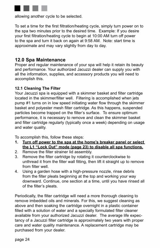
To accomplish this, follow these steps:1. Turn off power to the spa at the home’s breaker panel or select
the L1 “Lock Out” mode (page 23) to disable all spa functions.2. Remove the filter strainer lid assembly.3. Remove the filter cartridge by rotating it counterclockwise to
unthread it from the filter wall fitting, then lift it straight up to remove from filter well.
4. Using a garden hose with a high-pressure nozzle, rinse debris from the filter pleats beginning at the top and working your way
downward. Continue, one section at a time, until you have rinsed all of the filter’s pleats.
Periodically, the filter cartridge will need a more thorough cleaning to remove imbedded oils and minerals. For this, we suggest cleaning as above and then soaking the cartridge overnight in a plastic container filled with a solution of water and a specially formulated filter cleaner available from your authorized Jacuzzi dealer. The average life expec-tancy of a Jacuzzi filter cartridge is approximately two years with proper care and water quality maintenance. A replacement cartridge may be purchased from your dealer.

page 25
12.2 Draining and RefillingAbout every 3 months, you will want to replace the spa’s water. The fre-quency depends on a number of variables including the amount of use, attention paid to water quality maintenance, etc. You will know it is time for a change when you cannot control sudsing and/or you can no longer get the normal feel or sparkle to the water even though the key water balance measurements are all within the proper parameters.
WARNING! READ THIS BEFORE DRAINING: To prevent damage to the spa’s components, turn off power to the spa at the circuit breaker before draining it. Do not turn the power back on until your spa has been refilled.
CAUTION: There are certain precautions to keep in mind when draining your spa. If it is extremely cold, and the spa is outdoors, freezing could occur in the lines or the equipment, see “WINTERIZING” (page 26). On the other hand, if it is hot outdoors, do not leave the spa’s surface exposed to direct sunlight.
To drain spa: �. Remove synthetic skirt panel below the control panel (page �8).2. Remove drain hose behind synthetic skirt.3. Raise end of drain hose above water line, then remove drain hose
cap and attach garden hose to drain hose fitting.4. Lay drain hose down on ground, making sure water drains away from
spa.
After refilling, turn on power to the spa and follow the steps listed underthe “Spa Fill Up Procedure” (page �3).
12.3 Cleaning The Spa InteriorTo preserve the sheen of your spa’s surface, it is crucial that you avoid using abrasive cleaners or cleaners which have adverse chemical effect on the surface. If you are not certain as to the suitability of a particular cleanser, consult your authorized Jacuzzi dealer. Regardless of the cleanser used, use extreme care to assure that no soap residue is left on the surface. This could cause severe sudsing when the spa is refilled.
12.4 Pillow Care (J-220/J-230 Models Only)Remove and clean the headrest pillows as needed with soapy water using a cloth or soft-bristle brush. To maintain water resistance and luster, apply a quality vinyl conditioner once a month. Always remove the pillows when adding chemical shock treatment to the spa water. The

page 26
pillows can be returned to the spa when the sanitizer reading drops below 5 ppm.
12.5 Maintaining the CoverUsing the Jacuzzi insulating spa cover anytime the spa is not in use will significantly reduce your operating costs, heat-up time and maintenance requirements. To prolong the life of the cover, handle it with care and clean it regularly using mild soap and water. Periodic treatments with a special conditioner developed for Jacuzzi spa covers will help protect against deterioration caused by UV rays from the sun.
Never allow anyone to stand or sit on the cover, and avoid dragging it across rough surfaces.
12.6 Maintaining The Synthetic CabinetYour new spa’s synthetic cabinet requires little or no maintenance of any kind. To clean, simply wipe cabinet with a clean towel and mild soap solution.
CAUTIoN: Never spray cabinet with a garden hose for any rea-son since this action may induce an electrical short in the spa’s electrical equipment.
12.7 WinterizingYour Jacuzzi spa is designed to automatically protect itself against freezing when operating properly. During periods of severe freezing temperatures, you should check periodically to be certain that the elec-trical supply to the spa has not been interrupted. In extreme, bitter cold weather less than -20°F (-29°C), choose the F3 “Standard” skimming/heating mode to prevent freezing (page 23).
If you do not intend to use your spa, or if there is a prolonged power outage during periods of severe freezing temperatures, it is impor-tant that all water be removed from the spa and equipment to protect against damage from freezing. For expert winterization of your spa, contact your authorized Jacuzzi dealer. In emergency situations, damage can be minimized by taking the following steps:
�. Follow the directions on page 25 for draining the spa.2. As the water level drops below the seats, use whatever means nec-
essary to get the water out of the recessed seating areas and into the footwell.
3. When the water level ceases to drop, use whatever means avail-able to remove any remaining water from the footwell.

page 27
4. Turn off power to the spa.5. Remove the synthetic cabinet panel under the control panel and
locate the drain plugs on the front of the pump(s), (Figure-A, page �2). Remove plugs to allow water to drain out of pumps and heater. Note: Approximately one to two gallons will be released during this procedure. Use a wet/dry vacuum or other means to keep this from flooding the equipment compartment. Replace the drain plugs.
6. Re-install synthetic cabinet side panel and cover spa so that no casual moisture can enter into it.
Consult your authorized Jacuzzi dealer if you have any questions regarding winter use or winterizing.
12.8 Restarting Your Spa in Cold WeatherIf you want to start up your spa after it has sat empty for a time in freez-ing temperatures, be aware that the water remaining in certain sections of the piping may still be frozen. This situation will block water flow preventing the spa from operating properly and possibly damaging the equipment. We recommend you consult your authorized Jacuzzi dealer for guidance before attempting to re-start your spa under these condi-tions.
13.0 Water Quality MaintenanceMaintaining the quality of the water within specified limits will serve to enhance your enjoyment and prolong the life of the spa’s equipment. It is a fairly simple task, but it requires regular attention because the water chemistry involved is a balance of several factors. There is no simple formula, and there is no avoiding it. A careless attitude in regard to water maintenance will result in poor and potentially unhealthful con-ditions for soaking and even damage to your spa. For specific guidance on maintaining water quality, consult your authorized Jacuzzi dealer who can recommend appropriate chemical products for sanitizing and maintaining your spa.
CAUTION: Never store spa chemicals inside the spa’s equip-ment bay.
13.1 pH ControlpH is a measure of relative acidity or alkalinity of water and is mea-sured on a scale of 0 to �4. The midpoint of 7 is said to be neutral, above which is alkaline and below which is acidic. In spa water, IT IS VERY IMPoRTANT To MAINTAIN A SLIGHTLY ALKALINE CoNDI-

page 28
TIoN oF 7.2 to 7.8. Problems become proportionately severe the fur-ther outside of this range the water gets. A low pH will be corrosive to metals in the spa equipment. A high pH will cause minerals to deposit on the interior surface (scaling).
In addition, the ability of the sanitation agents to keep the spa clean is severely affected as the pH moves beyond the ideal range. That is why almost all spa water test kits contain a measure for pH as well as the sanitizer.
13.2 SanitizingTo destroy bacteria and organic compounds in the spa water, a sanitizer must be used regularly. Chlorine and bromine are the two most popular sanitizers used to date. Many other additives are available for your spa. Some are necessary to compensate for out-of-balance water, some aid in cosmetic water treatment and others simply alter the feel or smell of the water. Your authorized Jacuzzi dealer can advise you on the use of these additives.
CAUTION: Do not use chlorine tablets (trichlor) in your spa. This chemical can have an extremely corrosive effect on certain materials in the spa. Damage caused by use of this chemical, or improper use of any chemicals, is not covered under the spa’s warranty.
13.3 Optional CD Ozone Water Maintenance SystemIf you have elected to have your spa equipped with the optional Jacuzzi CD ozone water purification system you will find that your water stays fresh and clear with significantly less chemical sanitizer usage. You will also probably be able to go longer between complete spa drainings. The CD ozone unit operates in conjunction with low speed jets pump #�.
14.0 Error Conditions/Error MessagesYour spa has a self-diagnostic control system. The system will automatically display the following if a problem is detected.
14.1 Panel Displays SN1open sensor (heater is disabled) or shorted sensor (spa is deactivated). The high-limit temperature sensor is not func-tioning. Contact your authorized Jacuzzi dealer or qualified service technician.

page 29
14.2 Panel Displays SN2open or shorted sensor (heater disabled). The temperature sensor is not functioning. Contact your authorized Jacuzzi dealer or qualified service technician.
14.3 Panel Displays FL1Pressure switch is not closed when the pump is activated. Heater is deactivated. Proper flow of water is inhibited or pressure switch has malfunctioned. Check for proper water level, pump is primed and/or clogged filter. Contact your authorized Jacuzzi dealer or qualified service technician.
14.4 Panel Displays FL2Pressure switch is closed while pump is deactivated. Contact your authorized Jacuzzi dealer or qualified service techni-cian.
14.5 Panel Displays COLCool Condition - Temperature has dropped 20°F (��°C) below the current set temperature. The pump and heater have been activated to bring the temperature to within �5°F (8°C) of the set temperature. No corrective action is required. Note: during cold periods, you may consider increasing the number of filtration cycles (page 23).
14.6 Panel Displays ICEFreeze Protection - A potential freeze condition has been detected. No action is required. The pump and heater will operate to circulate and warm water through the plumbing until spa is out of danger. See “Winterizing” (page 26).
14.7 Panel Displays OHWater temperature is above acceptable limits. Do not enter spa! Water temperature has reached 112˚F (44˚C) and the low speed pump has activated to circulate water through heater. Contact your authorized Jacuzzi dealer or qualified service technician.
14.8 Panel Displays - - -The safety “Watchdog” software has been triggered and the spa is deactivated. A problem has been detected which could cause damage to the spa or its components. Contact your authorized Jacuzzi dealer or qualified service technician.

page 30
15.0 Troubleshooting ProceduresIn the event your Jacuzzi® spa is not working the way it should, please first review all the installation and operating instructions in this manual and check the message on the panel display. If you are still not satis-fied it is working properly, please follow the appropriate troubleshooting instructions below. Note: If any of the supply cords to the accessories are damaged, they must be replaced by authorized service personnel. Contact your authorized Jacuzzi dealer or qualified service technician.
15.1 None of the Components Operate (e.g. Pump, Light) Check the following:�. Is there power to the spa?2. Is the household circuit breaker tripped?3. Contact your authorized Jacuzzi dealer or qualified service technician.
15.2 Pump Does Not Operate but Light DoesPress the JETS � button:�. If no water movement is detected, make sure power is going to the
spa and check the water level. If it does not solve the problem, con-tact your authorized Jacuzzi dealer or qualified service technician.
2. The main pump operates but no water flows to jets. Pump may not be properly primed. This can happen after the spa is drained and
refilled. Press the JETS � button several times, never leaving the motor on for more than 5 to �0 seconds at a time. Turn power off and let the air out by loosening the cap on the diverter valve (J-220 models only) and/or remove the filter. Refer to section 9.2 (page �8). Make certain you tighten the diverter cap and/or reinstall the filter before turning on spa power and restarting the pump.
15.3 Poor Jet Action�. Press the JETS � button to make certain pump #� is on.2. open all air controls to their full on position (counterclockwise).3. Check for dirty filter. Clean, if necessary (section �2.� page 24).4. Make sure jets are all the way open (section �0.5 page 22).
15.4 Water is Too HotReduce thermostat setting.

page 3�
15.5 No Heat�. Check thermostat setting (section �0.� page 2�).2. Keep the spa cover in place while heating.3. Check the settings to see if your spa is in economy filtration/heating
mode (page 23).
Should checking the above steps fail to correct the problem, please call your dealer so that they may arrange service. We build the best spas in the industry. Nonetheless, we are always striving to improve the quality and features of our products.
Your input as a Jacuzzi spa owner is a cherished part of this process. If you have any comments or suggestions, or if you wish to be informed on any new products for your spa, please write to us.
CONgRATULATIONS on your good taste and welcome to the happiest and most relaxed family in the world!

page 32
16.0 J-210/J-220 Convertible Circuit Diagram (60Hz)This wiring diagram is used for the J-2�0/J-220 US/Canada �20/240 VAC (60Hz) convertible power models.
OptionalOzonator
O3
Standard 3-Wire 120 VAC Connection (60 Hz, 1 Phase, 15A Service)Use copper conductors ONLY. Wire size must be appropriate per NEC and/or local codes.
WHT
WHT
WHT
WHT
WHT
WHT
BLK
BLK
BLK
BLK
BLK
BLK
BLK
BLK
RED
RED
RED*
RED*
RED*
RED
Heater1.0 kW @ 120 VAC (3-wire connection)4.0 kW @ 240 VAC (4-wire connection)
Pressure Switch
Hi-limit/Freeze Sensor
Temperature Sensor
J2
J3
F120A250VSC-20
Main Pump
Spa Light
Transformer120 VAC
Optional 4-Wire 240/120 VAC Convertible Heater Connection1. Remove and discard the factory installed GFCI Cord.
2. Move RED* wire from TB1 position #1 to TB1 position #3 as shown below.
3. Permanently connect to the power supply. Use copper conductors ONLY.
Wire size must be appropriate per NEC and/or local codes.
4. If hot tub is to be operated on 30A service, make sure the jumper provided
at location JP1 #1&2 on the circuit board is installed. If hot tub is to be
operated on 40A service, remove the jumper JP1 #1&2 on the circuit board.
HILO
J1 Logic Jumper Settings (Factory Defaults Shown)JP� �-2 oN = 30A Logic (4-wire �20/240 VAC operation only)JP� �-2 oFF = 40A Logic (4-wire �20/240 VAC operation only)JP� 7-8 oN = °C Temperature DisplayJP� 7-8 oFF = °F Temperature Display
This device complies with Part 15 of theFCC rules. Operation is subject to the following two conditions:1. This device may not cause harmful
interference.2. This device must accept any inteference
received including interference that may cause undesired operation.
J20J2�
J�2
J�4
J�6
J��
J�5
J�3
J�7 J7 J8 J9 J�0
J5
J6Heater IN Heater oUT
F�
K5 K7 K8
J1
Control Panel
THERMSWITCH
7531
8642
To circuit board
GRN
Tb1
WHT
BLK
1
2
3
1
2
3
GR
OU
ND
GRN
Tb1
WHT
BLK
GR
OU
ND
WARNINg, ELECTRICAL SHOCK HAZARD ExISTS! Always remove power to spa before wiring and/or configuring the circuit board
Move Wire
HardWire Only
Plug-in GFCI Cord (US Models Only) ORHard Wire

page 33
17.0 J-230 Circuit Diagram (60Hz)This wiring diagram is used for all J-230 US/Canada 240 VAC (60Hz) dedicated power models.
OZ
ON
AT
OR
(O
PT
ION
AL)
O3
GR
NTB
1
Sta
nd
ard
240
VA
C, 3
-Wir
e C
on
nec
tio
n (
60H
z, 1
-Ph
ase
Ser
vice
)U
SE
CO
PP
ER
CO
ND
UC
TO
RS
ON
LY.
WIR
E S
IZE
MU
ST
B
E A
PP
RO
PR
IAT
E P
ER
NE
C A
ND
/OR
LO
CA
L C
OD
ES
RE
D
RE
D J6B
LKJ5
WH
T
WH
T
WH
T
RE
D
BLK
BLK
BLK
WH
T
BLK
RE
DR
ED
BLK
BLK
BLK
21
FLO
W S
WIT
CH
HI -
LIM
IT /
FR
EE
ZE
SE
NS
OR
TE
MP
ER
AT
UR
E S
EN
SO
R
J1
J2 J3
F1
30A
, 250
VS
C-3
0
PU
MP
1
PU
MP
2
TR
AN
SF
OR
ME
R24
0 V
AC
J4 F1
76
24
HI
HI
LO
Co
ntr
ol P
anel
SP
A L
IGH
T
J20
K1
K2
K3
K4
K5
K6
K7
K8
J21
J11
J12
J13
J14
J15
J16
J17
J18
J19
J7J8
J9J1
0
Thi
s de
vice
com
plie
s w
ith P
art 1
5 of
the
FC
C r
ules
. O
pera
tion
is s
ubje
ct to
the
follo
win
g tw
o co
nditi
ons:
1. T
his
devi
ce m
ay n
ot c
ause
har
mfu
l
inte
rfer
ence
.2.
Thi
s de
vice
mus
t acc
ept a
ny in
tefe
renc
e
rece
ived
incl
udin
g in
terf
eren
ce th
at m
ay
ca
use
unde
sire
d op
erat
ion.
Hea
ter
5.5
kW24
0 V
AC
JP1
4 23 1
65
87
Lo
gic
Ju
mp
er S
etti
ng
s (F
acto
ry D
efau
lts
Sh
ow
n)
JP1
1-2
ON
=
40A
Log
ic
JP1
1-2
OF
F =
50A
Log
ic (
Fac
tory
Def
ault
Set
ting)
JP1
3-4
ON
=
2 P
ump
Ope
ratio
n*JP
1 3-
4 O
FF
= 1
Pum
p O
pera
tion*
JP1
5-6
ON
=
60A
Log
ic (
Rem
ove
JP1
1-2
Jum
per)
JP1
5-6
OF
F =
Lea
ve O
ff fo
r 40
A o
r 50
A L
ogic
JP1
7-8
ON
=
Cel
sius
Tem
pera
ture
Dis
play
JP1
7-8
OF
F =
Fah
renh
eit T
empe
ratu
re D
ispl
ay

page 34
Standard 3-Wire 230 VAC Connection (50 Hz, 1 Phase Service)Use copper conductors ONLY. Wire size must be appropriate per NEC and/or local codes.
BLK
BLKBLU
BLU
BLUBLU
BLU
BLU
BRN
BRN
BRN
BRN
BRNBRN
BRN
Heater2.7kW @ 230 VAC
Pressure Switch
Hi-limit/Freeze Sensor
Temperature Sensor
J2
J3
Spa Light
Transformer230 VAC
J1 Logic Jumper SettingsJP� �-2 oN = 20A Logic (Factory Setting)JP� �-2 oFF = 30A LogicJP� 7-8 oN = °C Temperature Display (Factory Setting)JP� 7-8 oFF = °F Temperature Display
J20J2�
J�2
J�4
J�6
J��
J�5
J�3
J�7 J7 J8 J9 J�0
J5
J6 Heater IN Heater oUT
F�*
K5 K7 K8
J1
Control Panel
THERMSWITCH
7531
8642
OptionalOzonator
O3
F120A
250VSC-20
GRN
Tb1
BLU
BRN 1
2
GR
OU
ND Main Pump
HILO
HardWire Only
18.0 J-210/J-220 Export Circuit Diagram (50Hz)This wiring diagram is used for the J-2�0/J-220 Export 230 VAC (50Hz) dedicated power models.

page 35
19.0 J-230 Export Circuit Diagram (50Hz)This wiring diagram is used for all J-230 Export 230 VAC (50Hz) dedicated power models.
Opt
iona
l Ste
reo
And
Pow
er
Sup
ply
on J
-335
, J-3
45
Mod
els
Onl
y.
Pow
er S
uppl
y
OZ
ON
AT
OR
(O
PT
ION
AL)
O3
GR
NTB
1
230
VA
C 3
-Wir
e C
on
nec
tio
n (
50H
z, 1
-Ph
ase
Ser
vice
)U
SE
CO
PP
ER
CO
ND
UC
TO
RS
ON
LY.
WIR
E S
IZE
MU
ST
BE
A
PP
RO
PR
IAT
E P
ER
NE
C A
ND
/OR
LO
CA
L C
OD
ES
BLU
BLU J6
BR
NJ5
BR
N
WH
T
BLU
BLK
BLU
BLK
BR
N
BLU
BR
N
BLU
BLU
BR
NB
RN
BR
N
21
FLO
W S
WIT
CH
HI -
LIM
IT /
FR
EE
ZE
SE
NS
OR
TE
MP
ER
AT
UR
E S
EN
SO
R
J1
J2 J3
F1
20A
, 250
VS
C-2
0
PU
MP
1
PU
MP
2
TR
AN
SF
OR
ME
R24
0 V
AC
J4 F1
76
24
HI
HI
LO
Co
ntr
ol P
anel
SP
A L
IGH
T
J20
K1
K2
K3
K4
K5
K6
K7
K8
J21
J11
J12
J13
J14
J15
J16
J17
J18
J19
J7J8
J9J1
0
Hea
ter
2.7
kW @
23
0 V
AC
JP1
4 23 1
65
87
Lo
gic
Ju
mp
er S
etti
ng
s (F
acto
ry D
efau
lts
Sh
ow
n)
JP1
1-2
ON
=
20A
Log
ic (
Fac
tory
Def
ault
Set
ting)
JP
1 1-
2 O
FF
= 3
0A L
ogic
JP1
3-4
ON
=
2 P
ump
Ope
ratio
n*JP
1 3-
4 O
FF
= 1
Pum
p O
pera
tion*
JP1
5-6
ON
=
40A
Log
ic (
Rem
ove
JP1
1-2
Jum
per)
JP1
5-6
OF
F =
Lea
ve O
ff fo
r 20
A o
r 30
A L
ogic
JP1
7-8
ON
=
Cel
sius
Tem
pera
ture
Dis
play
JP1
7-8
OF
F =
Fah
renh
eit T
empe
ratu
re D
ispl
ay

page 36
Notes

page 37
Notes


Ozonator
O3
TB1
230 VAC, 3-Wire ConnectionUSE COPPER CONDUCTORS ONLY. WIRE SIZE MUST BE APPROPRIATE PER NEC AND/OR LOCAL CODES
21
Flow Switch
Hi-limit/Freeze Sensor
Temperature Sensor
J2
J3
F120A250VSC-20
Circ.Pump
MainPump
SpaLight
Transformer230 VAC
J4
HILO
GRN
Logic Jumper Settings
All Export 50 Hz Models:JP1 1-2 ON = 20A Logic*JP1 1-2 OFF = 30A Logic*Factory Jumper Setting
Temp. Jumper Settings (All Models):JP1 7-8 ON = Celsius Temp Display JP1 7-8 OFF = Fahrenheit Temp Display
BLU BRN
JP1
42
31
6 58 7
Heater Specifications• Export 50 Hz Model: 2.7 kW @ 230 VAC
J20
J21
J12
J14
J16
J11
J15
J13
J17 J7 J8 J9 J10
J5
J6
Heater IN Heater OUT
F1
K1
K2
K3
K4
K5 K7 K8
BLK
WHT
BRN
BRN
BLU
BLU
BLU
BRN
BRN
BLK BLU BRN BLU BRN
J1
Control Panel
Printed in The USA
Jacuzzi® Hot Tubs14525 Monte Vista Ave.Chino, CA 91710United Stateswww.jacuzzi.com
6530-322, Rev-C


![Rom J Morphol Embryol 2013, 54(1):205–210 R J M E CASE ... · PDF fileRom J Morphol Embryol 2013, 54(1):205–210 ISSN ... project report CEEX 68/2006 [3] shows that 650 000](https://img.pdfslide.us/doc/110x75/5aae038b7f8b9a07498b87b2/rom-j-morphol-embryol-2013-541205210-r-j-m-e-case-j-morphol-embryol-2013.jpg)