Embed Size (px)
Citation preview

1Mechatronics 2020 - Transducers
TRANSDUCERS
2Mechatronics 2020 - Transducers
TRANSDUCERS
•Different physical signals are transformed in electrical ones.
•Based on physical principles (i. e. a potentiometer measures the distance from a reference point through the variation of the resistance).
•It is important to establish what physical magnitude is measured and what electrical signal is provided.
•Order of magnitude of the physical quantity measured (if DT=100 °C thermocouple, for light temperature variations thermoresistors).
•Amplitude of the emitted electronic signal (amplification, rectifying, …).
•Data-sheet
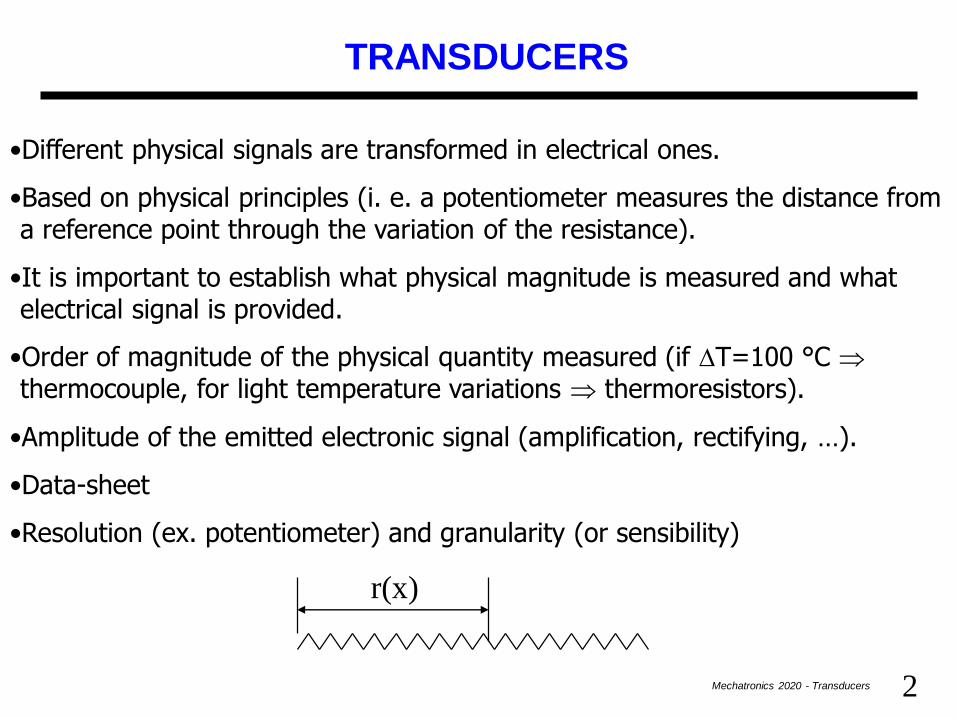
•Resolution (ex. potentiometer) and granularity (or sensibility)
r(x)
3Mechatronics 2020 - Transducers
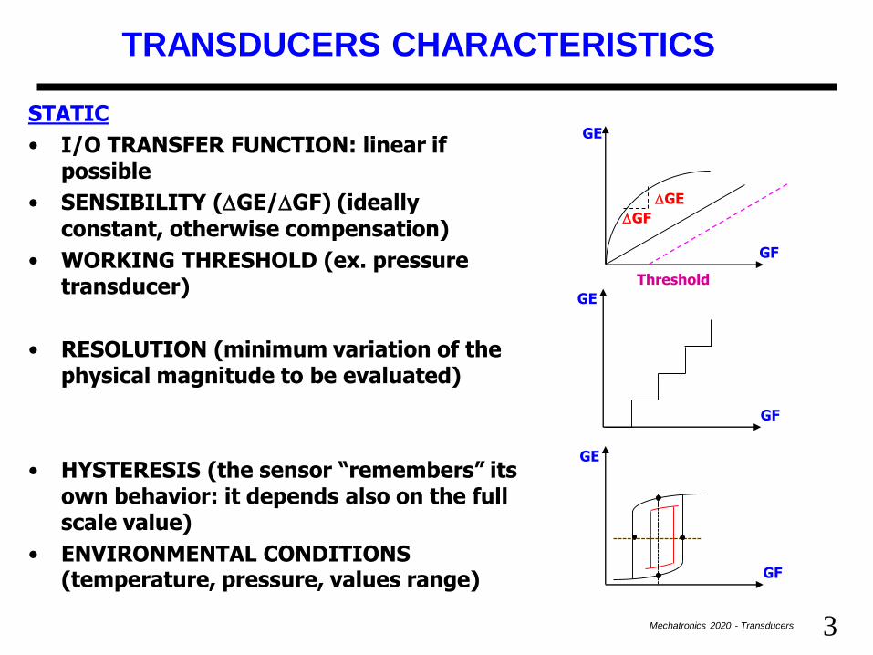
STATIC
• I/O TRANSFER FUNCTION: linear if possible
• SENSIBILITY (DGE/DGF) (ideally constant, otherwise compensation)
• WORKING THRESHOLD (ex. pressure transducer)
• RESOLUTION (minimum variation of the physical magnitude to be evaluated)
• HYSTERESIS (the sensor “remembers” its own behavior: it depends also on the full scale value)
• ENVIRONMENTAL CONDITIONS (temperature, pressure, values range)
TRANSDUCERS CHARACTERISTICS
DGE
DGF
GF
GE
GF
GE
GF
GE
Threshold

4Mechatronics 2020 - Transducers
DYNAMIC
• The capability of the transducer to couple
with the process time constant
• TRANSFER FUNCTION AND CUTOFF
FREQUENCY
stability
promptness (answwer velocity ex.
microwave oven and thermocouple)
-1
w
A
wC
• RELIABILITY/AFFORDABILITY:
work in specified conditions
graceful degradation
reversibility in case of overload
TRANSDUCERS CHARACTERISTICS

5Mechatronics 2020 - Transducers
LINEAR POSITION TRANSDUCERS
They are sensible to the object coordinates although it is steady (parametric)
We will distinguish:
•LINEAR POSITION TRANSDUCERS WITH RESISTIVE OR CAPACITIVE VARIATION (wire wound potentiometer, electro-optical, capacitive)
•LINEAR POSITION TRANSDUCERS WITH MAGNETIC COUPLE VARIATION (differential, variable reluctance)
•ANGULAR POSITION TRANSDUCERS (potentiometer, synchro, absolute and incremental encoders)

6Mechatronics 2020 - Transducers
WIREWOUND POTENTIOMETER
r(x)
R(L)
r’(x’)
R L
x1R
L
x'(x)r' R
L
xr(x)
x V E L
x
R
E L
xR
r' r
Er V
It is sensible to the coordinate of anobject although that object isstationary. The transducer will beparametric that is it will provide thevariation of its internal resistance vsthe variation of the cursor position.
If the potentiometer is crossed by a constant current the measurement becomes a voltage measure

7Mechatronics 2020 - Transducers
WIREWOUND POTENTIOMETER: Problems
• SENSIBILITY:
a) The resistance does not change with continuity but with steps. A carbon-resistance could be used, but aging, abrasions and temperature can affect the measurements;
b) The ouptut impedance is not constant and in particular is maximum in the center (R/4). A decoupling buffer must be employed;
c) Is the output depending on the temperature? No, if the variation is homogeneous along the transducer.
•LOAD EFFECTS
a) The friction between the cursor and the surface creates a threshold below which the transducer does not change its output;
b) This together with the cursor elasticity could introduce a possible hysteresis in the transfer function
+E
cursor
x
V

8Mechatronics 2020 - Transducers
The connection of the cursor and the potentiometer is carried out by means of photo-electric material.
ELECTRO-OPTICAL TRANSDUCER
Material photo-conductive
Material conductive
Material
resistive
Light foil E
Vout
E
cursor
EQUIVALENT CIRCUIT
9Mechatronics 2020 - Transducers
ELECTRO-OPTICAL TRANSDUCER
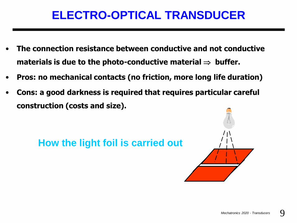
• The connection resistance between conductive and not conductive
materials is due to the photo-conductive material buffer.
• Pros: no mechanical contacts (no friction, more long life duration)
• Cons: a good darkness is required that requires particular careful
construction (costs and size).
How the light foil is carried out
10Mechatronics 2020 - Transducers
CAPACITIVE POTENTIOMETER
H
L
~
eC2C1
d
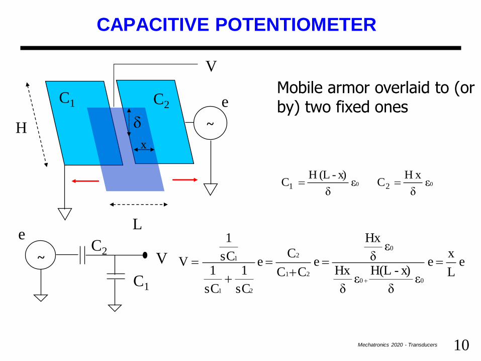
Mobile armor overlaid to (or by) two fixed ones
0 0 ε δ
xH Cε
δ
x)-(L H C 2 1
x
~C2
C1
V e L
x e
εδ
x)-H(Lε
δ
Hx
εδ
Hx
e CC
C e
sC
1
sC
1sC
1
V
0 0
0
2 1
2
21
1
V
e

11Mechatronics 2020 - Transducers
CAPACITIVE POTENTIOMETER
• Output impedance 021
o
sHLε
δ
C Cs
1 Z
High due to e0 (8.85*10-12 F/m).
To raise up the working frequency complicates the measurement since causes rectifying problems.
• Border effects
The closer the armor are, the flatter will be the curve below and above a certain distance.
V
x
• No contacts so longer average life
12Mechatronics 2020 - Transducers
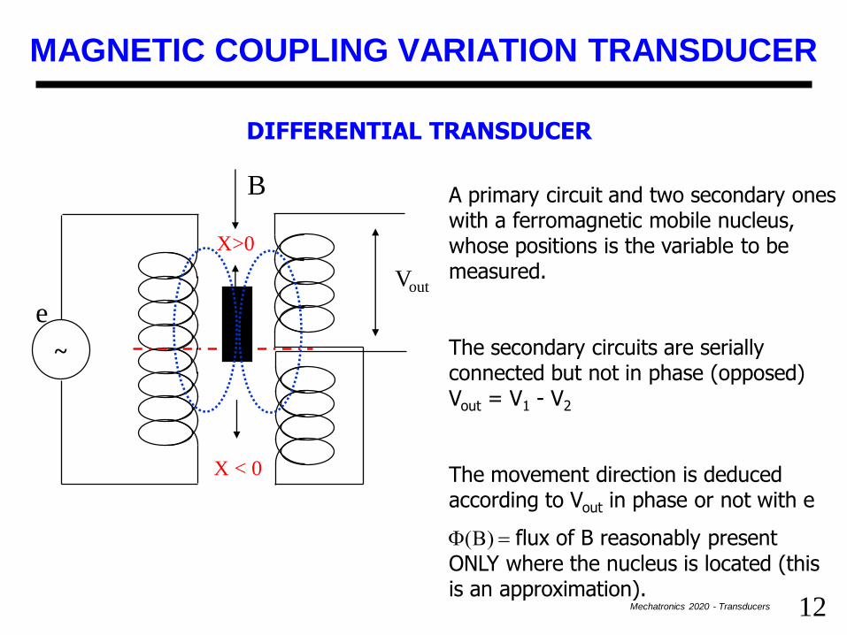
MAGNETIC COUPLING VARIATION TRANSDUCER
DIFFERENTIAL TRANSDUCER
~
e
Vout
X>0
X < 0
A primary circuit and two secondary ones with a ferromagnetic mobile nucleus, whose positions is the variable to be measured.
The secondary circuits are serially connected but not in phase (opposed) Vout = V1 - V2
The movement direction is deduced according to Vout in phase or not with e
F(B) flux of B reasonably present ONLY where the nucleus is located (this is an approximation).
B

13Mechatronics 2020 - Transducers
DIFFERENTIAL TRANSDUCER
•For every coil of a reel the flux of B is:
F = BS (S section of a coil and also of the nucleus)
•The flux chained to each coil is related to the n° of coils crossed by the magnetic field force lines (N1 are relative to the first reel in the secondary circuit and N2 in the second one):
F1 = F N1 F2 = F N2
•Due to the Faraday-Neumann law a flux variation induces a electromotive force in
the coil crossed by the force lines of the magnetic field.
•Also the viceversa is valid: a time-variable f.e.m causes a magnetic field flux whose derivative time the n° of crossed coils is equail to the f.e.m. itself
22 11 Ns- V e Ns- V quindi dt
d- f.e.m. FF
F thus

14Mechatronics 2020 - Transducers
DIFFERENTIAL TRANSDUCER
FF
x 2
L nN e x
2
L nN
s L n- sN- e
s2s1
p pnp density of coils in the primary circuit in front of the nucleus.
ns density of coils on the secondary circuit in front of the nucleus whose height is L.
By replacing we obtain e L
x
n
2n VVV
p
s
21
This is till a linear relationship between the measured voltage and the displacement of the nucleus vs the reference position (in this sense the transducer is differential). Often, moreover, ns=np.
It should be used at low frequencies since the output impedance is lower in this case (jwZL).

15Mechatronics 2020 - Transducers
VARIABLE INDUCTANCE TRANSDUCER
x
A
A ferromagnetic nucleus with ‘C’ shape is equipped with a mobile ferromagnetic foil in front of it.
The closer the foil, the greater is the flux of the magnetic field, and greater is the inductance effect in the circuit (see after).
B
nI
B di flusso
tomotriceforzamagne magnetica riluttanza
FR =
If the air area between nucleus and foil is small we can consider the system as ferromagnetic circuit into which the reluctance plays a role similar the resistor in electric circuits to which a similar definition can be applied
magnetic reluctancemagnetomotive force
flux of B
16Mechatronics 2020 - Transducers
VARIABLE INDUCTANCE TRANSDUCER
μ
1
A
L
ii
i
iR
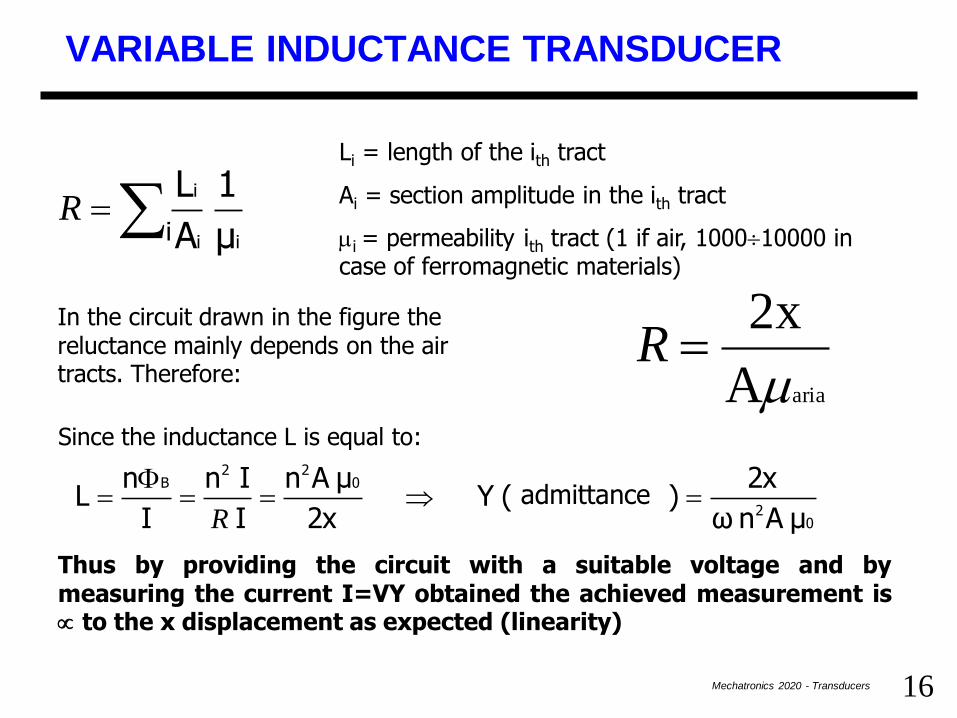
Li = length of the ith tract
Ai = section amplitude in the ith tract
mi = permeability ith tract (1 if air, 100010000 in case of ferromagnetic materials)
In the circuit drawn in the figure the reluctance mainly depends on the air tracts. Therefore:
A
2x
ariamR
Since the inductance L is equal to:
02
022
B
μA n ω
2x a)(ammettenzY
2x
μA n
I
I n
I
n L
F
R
Thus by providing the circuit with a suitable voltage and bymeasuring the current I=VY obtained the achieved measurement is to the x displacement as expected (linearity)
admittance

17Mechatronics 2020 - Transducers
VARIABLE INDUCTANCE TRANSDUCER
• Typical usage: two transducers
• When the distance x augments the second transducer compensates the ‘fraying’ of the force lines that would modify the value of the section A
• The coil number can be used to tune the transducer sensibility
• A bridge circuit is used to carry out the differential measurement requested by two transducers
• The measurement can be done even at relatively low frequencies but normally is done at 100 Hz – 1 KHz
• Possible application to measure very hot objects without any dangerous contact
Y2 = k [L d - x ]
Y1 = k x
d
L
18Mechatronics 2020 - Transducers
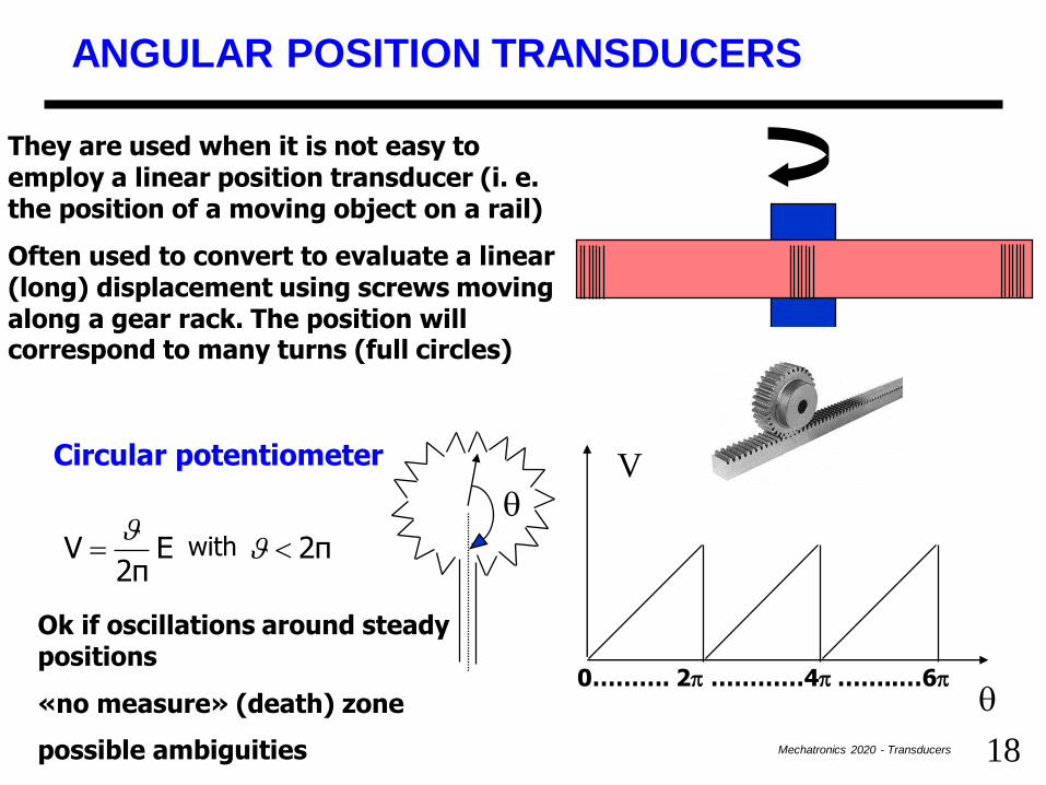
ANGULAR POSITION TRANSDUCERS
They are used when it is not easy to employ a linear position transducer (i. e. the position of a moving object on a rail)
Often used to convert to evaluate a linear (long) displacement using screws moving along a gear rack. The position will correspond to many turns (full circles)
V
Circular potentiometer
2π con E 2π
V
Ok if oscillations around steady positions
«no measure» (death) zone
possible ambiguities
0………. 2p …………4p ……..…6p
with

19Mechatronics 2020 - Transducers
ENCODERS (optical measurement systems)
A disk-plate equipped with windows transparent to the light interchanged with others opaque
The light is provided by a LED and received (when possible) by a photomultiplier (phototransistor)
Every window provides a binary information
The shaft is connected to the object of which we want to calculate the angular position or velocity

20Mechatronics 2020 - Transducers
ABSOLUTE ENCODER
Angular codification with 16 different values per every angle 4 bits: 4 concentric crowns are used with opaque/transparent windows on a 1 by 1, or 2 by 2, 4 by 4 and 8 by 8 basis. Minimum step is 22.5°
4 LED + phototransistor couples are necessary suitably aligned
Gray codification to avoid that 2 or more bits commute simultaneously (aligning and lighting errors)

21Mechatronics 2020 - Transducers
ABSOLUTE ENCODERS
• Cheap and with good precision for typical angular rotations
• If more N° of turns?
• What is the movement direction?
POSSIBLE SOLUTION
• If rotating in only one sense: external sectors are counted through a hw counter (bidirectional: it can increment or decrement its value): when the count reach 2^N a turn has been performed
• But if the direction can be changed no other possibility than using an incremental encoder

22Mechatronics 2020 - Transducers
INCREMENTAL ENCODER
Two concentric crowns 1/4 of the period phase shifted
Two LED/phototransistors couples (1 light, 0 darkness)
AB
Clock-wise rotation
A
B
A
B
Counter-clockwise rotation
t=0
A
B

23Mechatronics 2020 - Transducers
INCREMENTAL ENCODER
•Minimum angle to be measures = 1/2 window
•Direction inverting detectable
•Counting algorithm
A
B
S1 S2 S3
P 0 +1
P 1 -1
N 0 -1
N 1 +1
0 P -1
1 P +1
0 N +1
1 N -1
•Output = pulses
•Pulses must be read by a microprocessor or if too fast through a counter
24Mechatronics 2020 - Transducers
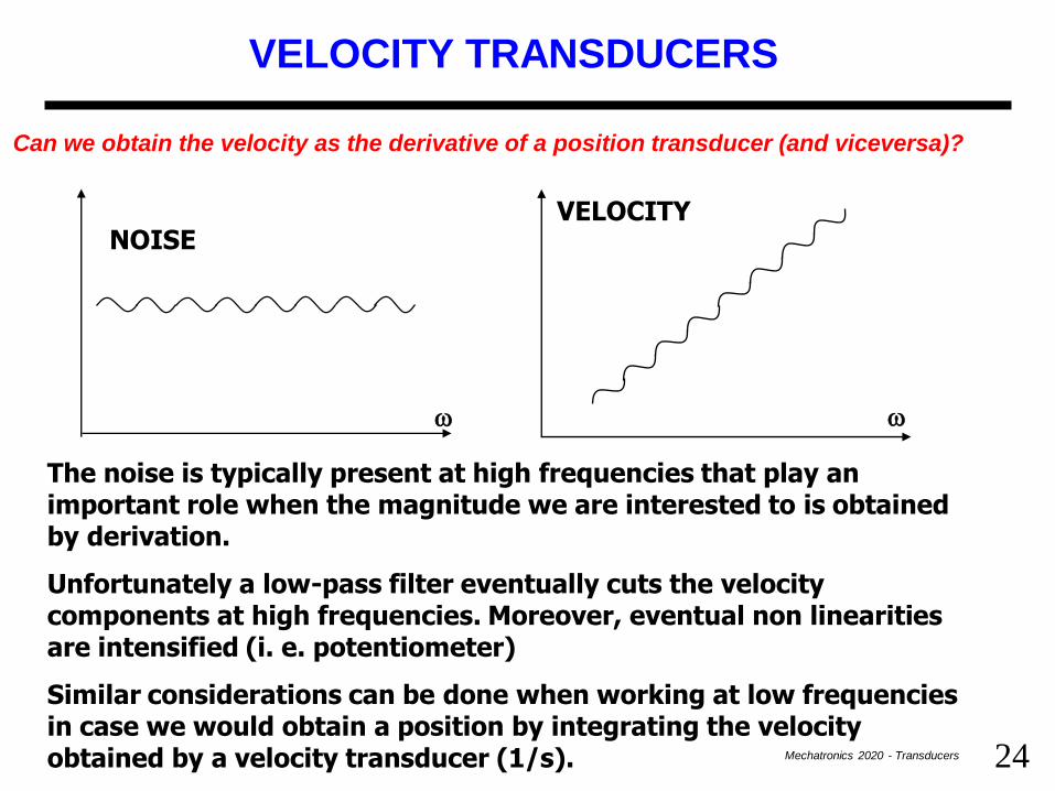
VELOCITY TRANSDUCERS
Can we obtain the velocity as the derivative of a position transducer (and viceversa)?
NOISE
w w
VELOCITY
The noise is typically present at high frequencies that play an important role when the magnitude we are interested to is obtained by derivation.
Unfortunately a low-pass filter eventually cuts the velocity components at high frequencies. Moreover, eventual non linearities are intensified (i. e. potentiometer)
Similar considerations can be done when working at low frequencies in case we would obtain a position by integrating the velocity obtained by a velocity transducer (1/s).

25Mechatronics 2020 - Transducers
LINEAR VELOCITY TRANSDUCER
xV0
v
Electromagnetic transducer
A nucleus of ferromagnetic material moving within a solenoid (permanent magnet).
Measured voltage flux variation therefore to the velocity.
( )vn -
dt
dxn -
dt
N d V
(densità) lunghezza di unitàper spire di numeron nx N
magnete ilcon econcatenat spire n N ,permanente magnete flussoΦ N Φ
B B
Bc
0
c
c B Bcc
FFF
F
•Approximated measurements
•Suitable to small velocities: if big it is better to transform the linear displacement into an angular one measuring the angular velocity
FB permanent magnet flux, NC coils enchained with the magnet N is the coil number vs length unit (density)
26Mechatronics 2020 - Transducers
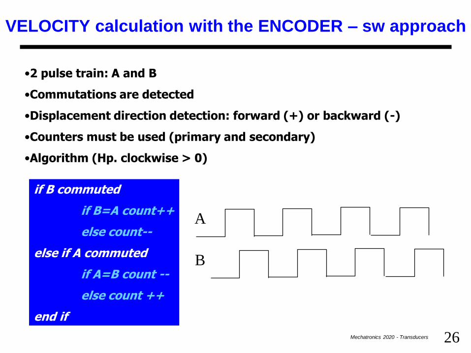
VELOCITY calculation with the ENCODER – sw approach
•2 pulse train: A and B
•Commutations are detected
•Displacement direction detection: forward (+) or backward (-)
•Counters must be used (primary and secondary)
•Algorithm (Hp. clockwise > 0)
A
B
if B commuted
if B=A count++
else count--
else if A commuted
if A=B count --
else count ++
end if

27Mechatronics 2020 - Transducers
VELOCITY CALCULATION
Encoder pulses are counted into a interval of time
DT
The period between two pulses is evaluated
It’s an average value!
Tck
28Mechatronics 2020 - Transducers
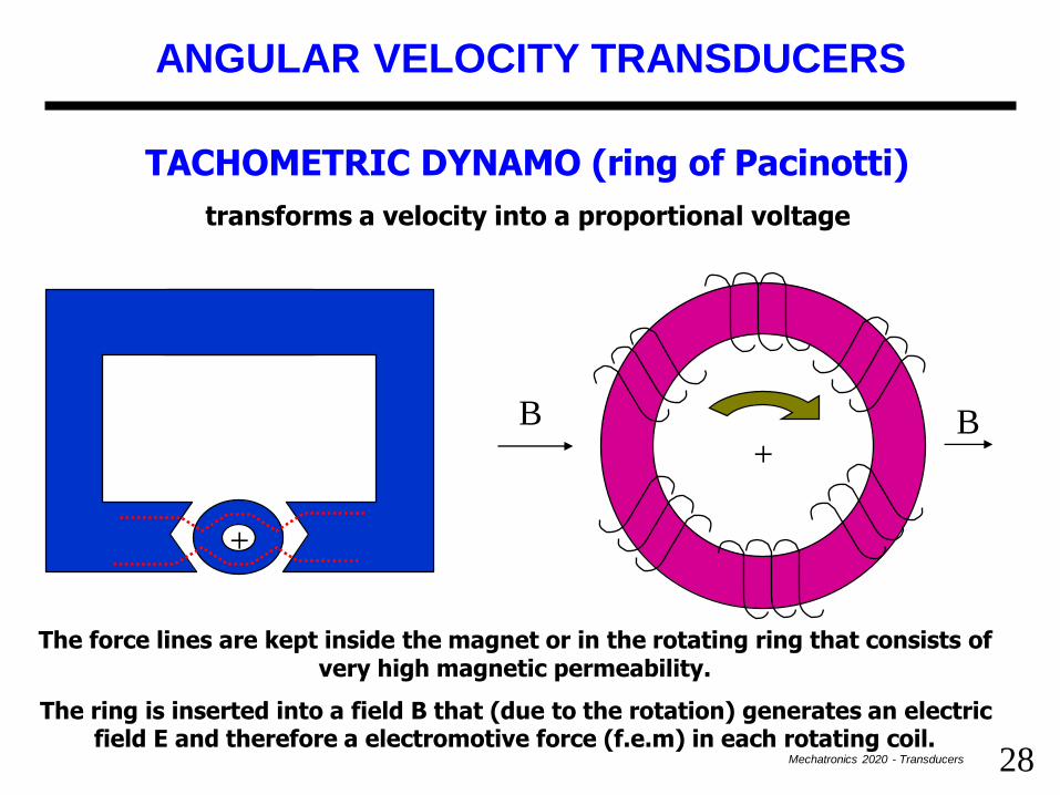
ANGULAR VELOCITY TRANSDUCERS
TACHOMETRIC DYNAMO (ring of Pacinotti)
transforms a velocity into a proportional voltage
+
+
B B
The force lines are kept inside the magnet or in the rotating ring that consists of very high magnetic permeability.
The ring is inserted into a field B that (due to the rotation) generates an electric field E and therefore a electromotive force (f.e.m) in each rotating coil.

29Mechatronics 2020 - Transducers
TACHOMETRIC DYNAMO
Bv
EE
v
B
Within the coils the f.e.m generated by the movement of the ring in the field are equal and opposite no contribute ≠ 0
dl EV
B E v
However if we insert two contact clamps that take current on top and bottom of the ring (where the dl element is parallel to E) a f.e.m 0 can be measured
30Mechatronics 2020 - Transducers
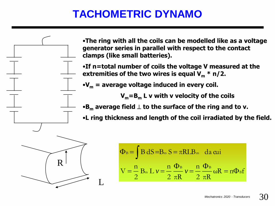
TACHOMETRIC DYNAMO
•The ring with all the coils can be modelled like as a voltage generator series in parallel with respect to the contact clamps (like small batteries).
•If n=total number of coils the voltage V measured at the extremities of the two wires is equal Vm * n/2.
•Vm = average voltage induced in every coil.
Vm=Bm L v with v velocity of the coils
•Bm average field to the surface of the ring and to v.
•L ring thickness and length of the coil irradiated by the field.
R
L
fn ωRπR
2
n
πR
2
n L B
2
n V
cuida πRLB S B dS B
B
BB
m
mmB
FF
F
F
vv

31Mechatronics 2020 - Transducers
TACHOMETRIC DYNAMO
High voltages immediately usable (10V/1000 rpm)
Low output impedance
‘ripple’ effect due to the construction methods (1-2%)
Mobile contacts (brushes and plates)
Curt variation when passing from a plate to the successive one
f.e.m induced sinusoidal if uniform B field
No filtering since it depends on therotation velocity
Use of generators without clamps to prevent from the noise due to sliding contacts
t
V
32Mechatronics 2020 - Transducers
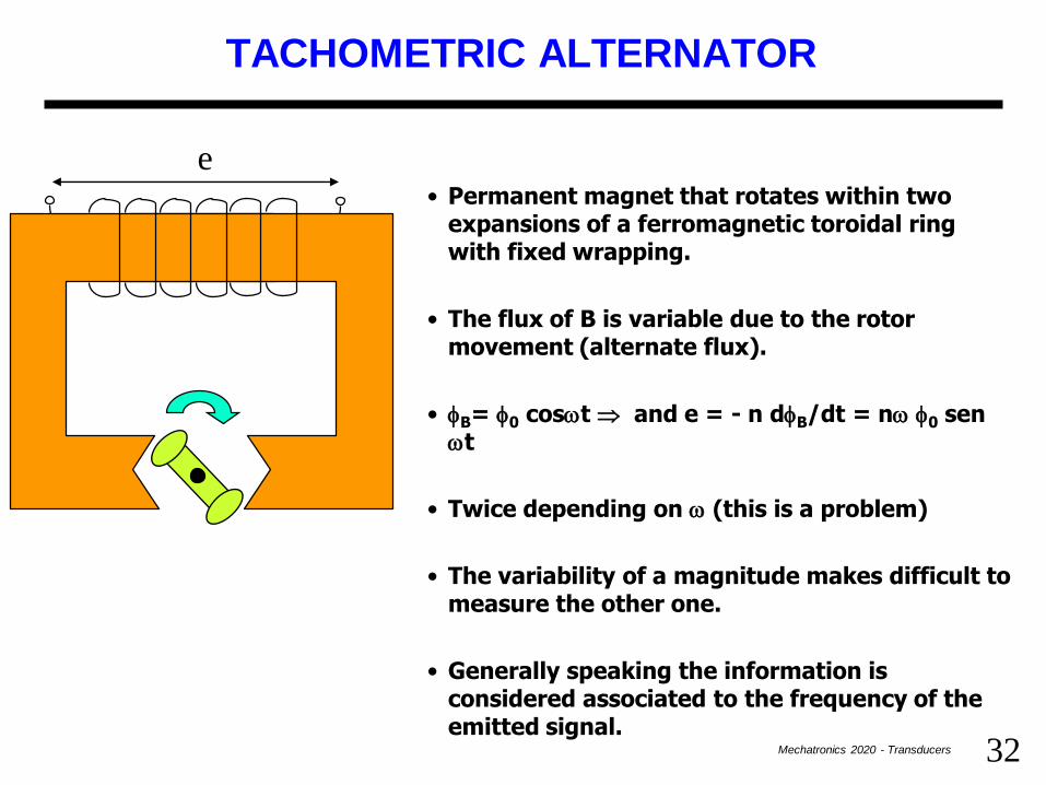
TACHOMETRIC ALTERNATOR
• Permanent magnet that rotates within two expansions of a ferromagnetic toroidal ring with fixed wrapping.
• The flux of B is variable due to the rotor movement (alternate flux).
• B= 0 coswt and e = - n dB/dt = nw 0 senwt
• Twice depending on w (this is a problem)
• The variability of a magnitude makes difficult to measure the other one.
• Generally speaking the information is considered associated to the frequency of the emitted signal.
e

33Mechatronics 2020 - Transducers
INDUCTION-BASED GENERATOR
• A rotating machine with two solenoidal stators and 1 rotors acting like as a squirrel cage with rectilinear conductors and 2 connecting rings.
rotor
~
e
• Due to the rotation the first wrapping couples with the cage and this in turn with the second one generating induced voltages.
• If the rotor is steady no voltage is generated.
• The first stator is AC power supplied. A magnetic field B arises that creates induced currents in the rotor conductors (due to the its movement).
• On turn this induces a voltage in the coils of the second stator.
Stator 1
Stator 2
34Mechatronics 2020 - Transducers
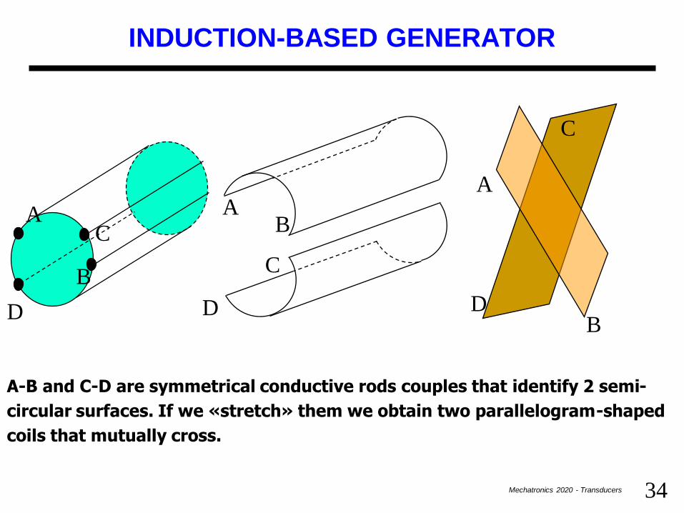
INDUCTION-BASED GENERATOR
A
B
C
D
A
B
C
D
A-B and C-D are symmetrical conductive rods couples that identify 2 semi-
circular surfaces. If we «stretch» them we obtain two parallelogram-shaped
coils that mutually cross.
AB
C
D
35Mechatronics 2020 - Transducers
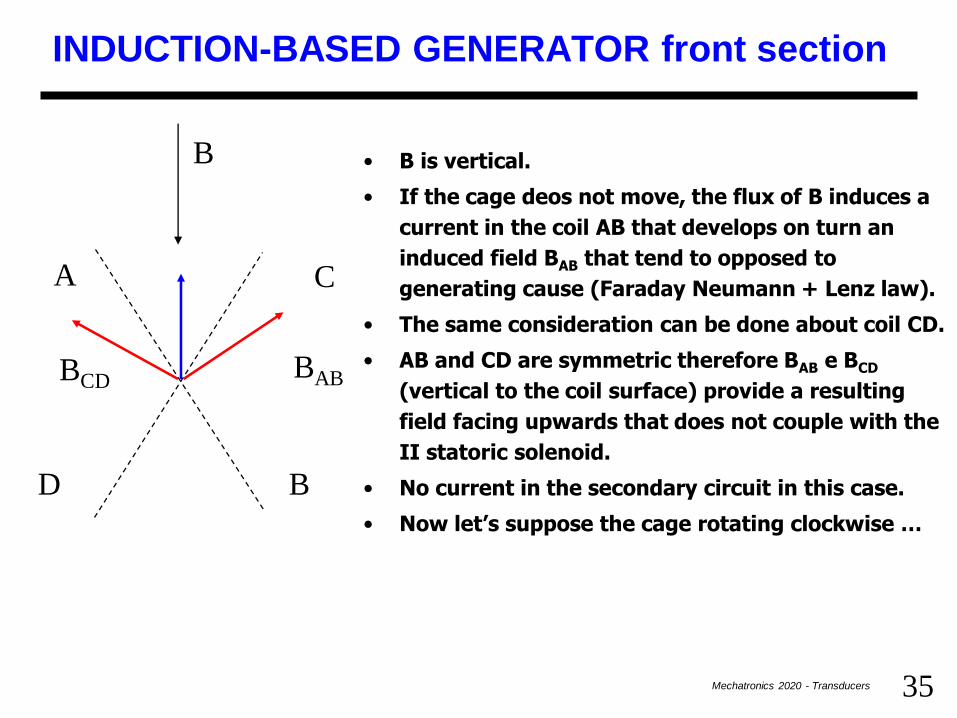
INDUCTION-BASED GENERATOR front section
• B is vertical.
• If the cage deos not move, the flux of B induces a
current in the coil AB that develops on turn an
induced field BAB that tend to opposed to
generating cause (Faraday Neumann + Lenz law).
• The same consideration can be done about coil CD.
• AB and CD are symmetric therefore BAB e BCD
(vertical to the coil surface) provide a resulting
field facing upwards that does not couple with the
II statoric solenoid.
• No current in the secondary circuit in this case.
• Now let’s suppose the cage rotating clockwise …
A
B
C
D
BABBCD
B

36Mechatronics 2020 - Transducers
INDUCTION-BASED GENERATOR front section
• B is vertical.
• If the cage rotates, the flux of B crossing the AB coil
diminishes (the effective coil surface is smaller).
• This induces a current in the coil AB and an induced
field BAB that opposes to the generating cause
therefore this time is downward oriented (i. e.
strengthen the field whose flux diminishes).
• About the CD coil the consideration is similar.
• This time BAB and BCD (vertical to the coil surface)
provide a horizontal resulting field that coupes with
the secondary solenoidal stator.
• An induced current is born in the secondary and a
f.e.m with frequency equal to the power supply e(t),
direction depending on the rotation type and
amplitude proportional to the velocity.
A
B
C
DBAB
BCD
B
Conditioning network: synchronous rectifier

37Mechatronics 2020 - Transducers
R
C
CAPACITIVE CHARGE/DISCHARGE TRANSDUCER
• The produced output features constant amplitude and
variable frequency (the velocity to be measured)
• When the ring turns the capacitor charges and
discharges alternatively
• The maximum charge value is E, the discharge is
made through the R resistor
• Every round the capacitor is charged/discharged
twice
•Frequency depends on the rotation velocity (max.
4/T to allow C to discharge)
•The output variable is an angular position (if
related to a time velocity)
• A reversible frequency-meter made up by a pulse
counter can be used. Reversible to estimate the
rotation sense
U
E
E
T/2 (T rounding period)
t=RC

38Mechatronics 2020 - Transducers
CAPACITIVE CHARGE/DISCHARGE TRANSDUCER
• As an alternative a low pass filter can be used (approximated integrator) with R’C’ >> T/2
• The output will be average of the voltage provided by the transducer
• V0 =2ERC/T = 2fERC
• f=rotation frequency
•If the rotation is inverted the sign is inverted
•The integrator is less precise than the frequency-meter and limits the velocity measurements (since the discharge must happen in a time = to 5RC that corresponds to T/4 be careful to the size of R and C).
+
-
R’
C’
V0U
39Mechatronics 2020 - Transducers
ACCELERATION TRANSDUCERS
• Same problems are before if acceleration is obtained as derivative of the velocity
• The acceleration is independent on the considered reference system
• No need of circuit that refer the measuremente to a fixed reference point (origin)
• The acceleration will be measured on a suitable point and then it will be valid for every system into which the object is moving
• Sometimes single and double integration to achieve position and velocity (critical at low frequencies and need of expensive hw to have enough accuracy)
40Mechatronics 2020 - Transducers
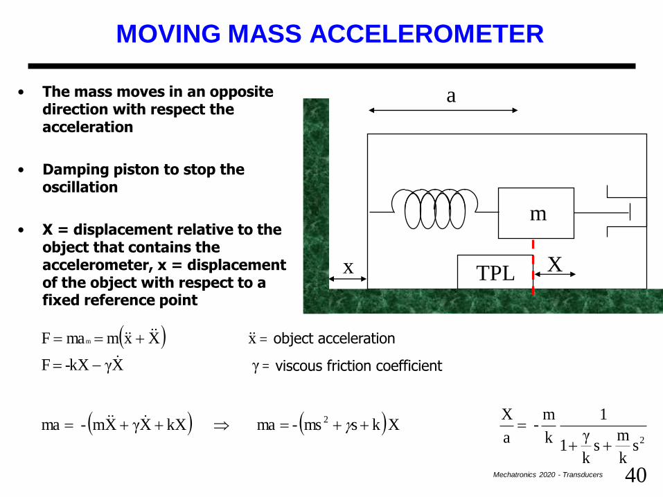
MOVING MASS ACCELEROMETER
• The mass moves in an opposite direction with respect the acceleration
• Damping piston to stop the oscillation
• X = displacement relative to the object that contains the accelerometer, x = displacement of the object with respect to a fixed reference point
x
m
TPL X
a
( )
( ) ( )2
2
sk
m s
k
γ1
1
k
m-
a
X X ks ms- ma kX X γ Xm- ma
viscosoattrito coeff. γ X γ kX- F
involucro one accelerazi x X xm maF m
object acceleration
viscous friction coefficient
41Mechatronics 2020 - Transducers
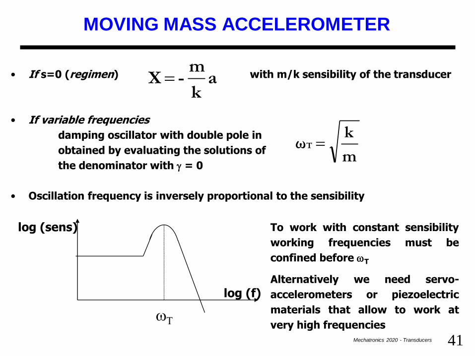
MOVING MASS ACCELEROMETER
• If s=0 (regimen) with m/k sensibility of the transducer
• If variable frequencies
damping oscillator with double pole in
obtained by evaluating the solutions of
the denominator with = 0
• Oscillation frequency is inversely proportional to the sensibility
ak
m - X
m
k ωT
log (f)
log (sens)
wT
To work with constant sensibility
working frequencies must be
confined before wT
Alternatively we need servo-
accelerometers or piezoelectric
materials that allow to work at
very high frequencies
42Mechatronics 2020 - Transducers
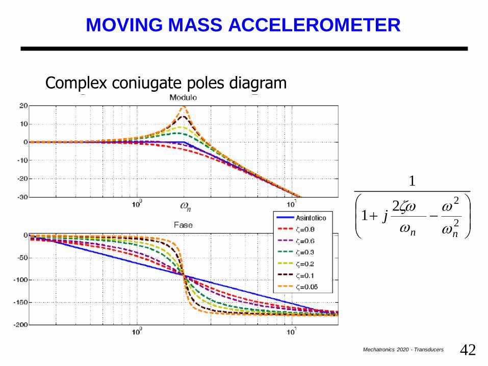
MOVING MASS ACCELEROMETER
2
221
1
nn
jw
w
w
w
Complex coniugate poles diagram
43Mechatronics 2020 - Transducers
SERVO-ACCELEROMETER
m
TPL AGm
R
Torque
Motor
U
a
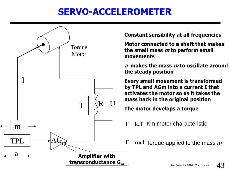
Constant sensibility at all frequencies
Motor connected to a shaft that makes the small mass m to perform small movements
a makes the mass m to oscillate around the steady position
Every small movement is transformed by TPL and AGm into a current I that activates the motor so as it takes the mass back in the original position
The motor develops a torque
m massa alla dovuta coppia mal
motore del ticacaratteris k Ik mm
l
I
Amplifier with transconductance Gm
Km motor characteristic
Torque applied to the mass m

44Mechatronics 2020 - Transducers
SERVOACCELEROMETER
a k
mRl
kR RIU
mm
m
When the system is stable the motor torque = oscillating mass torque
We introduced in the system a very sophisticated «spring» (damping factor) made up by the amplifier, the transconductance, the motor whose ‘elasticity constant’ is (St transducer sensibility):
l
k Gm A S
x
l
k Gm A S x
x
Fk
m
t
m
t
eq D
D
D
Constant sensibility
45Mechatronics 2020 - Transducers
OBSERVATIONS
•Several parameters allow to change the sensibility. The most
suitable one is the resistance R
•The elasticity constant depends on electrical parameters and not
only mechanical ones the spring can be improved without changing
the sensibility.
•No damping oscillation; components can be more easily controlled
•In normal conditions the parts of the transducer are in fixed
positions: better linearity
•TPL is linear if small m movements, not linear if large oscillations
•Not suitable at high frequencies (100 KHz). In this case a
piezoelectric ceramic accelerometer is advisable
46Mechatronics 2020 - Transducers
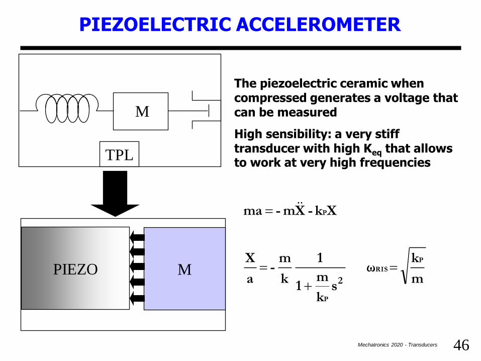
PIEZOELECTRIC ACCELEROMETER
M
TPL
PIEZO M
The piezoelectric ceramic when compressed generates a voltage that can be measured
High sensibility: a very stiff transducer with high Keq that allows to work at very high frequencies
m
k ω
sk
m 1
1
k
m -
a
X
X k- Xm - ma
P
RIS
P
P
2

47Mechatronics 2020 - Transducers
PIEZOELECTRIC EFFECT
Piezoelectric effect: a material that if compressed produces a measurable voltage or conversely if subject to a electric field can distort (reversibility).
Typical materials: titanate of Ba (BaTiO3) o PZLT (Piezo Lead Zirconate Titanate).
A piezoelectric crystal corresponds to a lattice with oxygen atoms in the vertices, metallic atoms in the face centers and in the a heavy atom in the center located in the minimum energy seat (fig. 1).
This structure is metastable (easy to modify).
If an electric external field is present, the Titanium o Zirconium atom moves from its steady position and causes an imbalance that transforms the crystal in an electric dipole (fig. 2).
The phenomenon can be detected up to a characteristic (Curie) temperature. Above this threshold the thermal agitation makes it to disappear.

48Mechatronics 2020 - Transducers
PIEZOELECTRIC EFFECT
The previous property is used to obtain anisotropic PZT materials.
In nature (fig. 1) PZT materials do not have preferred orientations so they are poor to deform or to provide an electric signal if warped.
Artificially, conversely, the PZT are warmed up beyond the Curie temperature and undergo to an intense electric field during the chilling that makes the dipoles to uniformly orient so as to have a steady polarization (fig. 2).
This stable polarization causes an overall deformation of the material determining a slight stretching. If now an external electric field is applied in the same direction of the polarization (but less coherently) the material will compress since the direction of the field is not completely parallel to the polarization (fig. 3). This behavior can be considered present up to a limit value of the field said coercive field.
The phenomenon is dual: if compressed or stretched, electrical charges can arise on the surface material dual with respect to the internal field.
49Mechatronics 2020 - Transducers
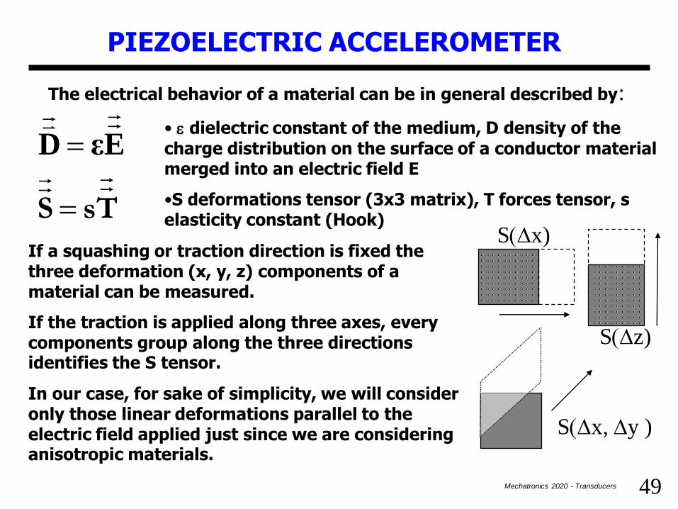
PIEZOELECTRIC ACCELEROMETER
The electrical behavior of a material can be in general described by:
Ts S
Eε D• e dielectric constant of the medium, D density of the charge distribution on the surface of a conductor material merged into an electric field E
•S deformations tensor (3x3 matrix), T forces tensor, s elasticity constant (Hook)
If a squashing or traction direction is fixed the three deformation (x, y, z) components of a material can be measured.
If the traction is applied along three axes, every components group along the three directions identifies the S tensor.
In our case, for sake of simplicity, we will consider only those linear deformations parallel to the electric field applied just since we are considering anisotropic materials.
S(Dz)
S(Dx, Dy )
S(Dx)

50Mechatronics 2020 - Transducers
Dx
PS=sT where T= P = force on the surface = F/A
S=streching DX/L, s elasticity constant
Eh' Ts S
Th
Eε D
PIEZO M
For PZT materials previous equations are different: a new h coefficient introduces the effect in terms of charges distribution due to the mechanical action.
Let’s suppose now that a small mass M that is moving with a acceleration compresses the PZT (or viceversa) and lets’ evaluate the transducer sensibility.
Due to the acceleration a compression force arises F=Ma by the mass M towards the PZT material.
The force tensor T is, T=Ma/A (A contact surface).
Suitable metal plates (plaques) to achieve the charges so as to measure a corresponding voltage. The cylindric piezoelectric transducer is equivalent to a capacitor
cannot work in direct current.
+++
+++
---
---
PIEZOELECTRIC ACCELEROMETER
51Mechatronics 2020 - Transducers
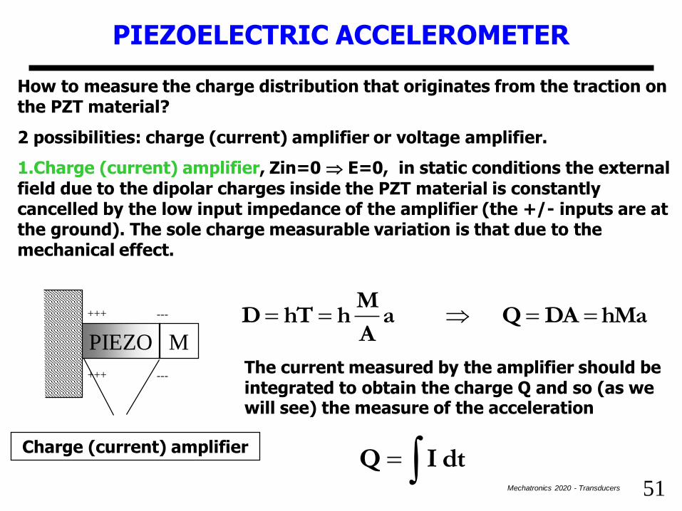
PIEZOELECTRIC ACCELEROMETER
How to measure the charge distribution that originates from the traction on the PZT material?
2 possibilities: charge (current) amplifier or voltage amplifier.
1.Charge (current) amplifier, Zin=0 E=0, in static conditions the external field due to the dipolar charges inside the PZT material is constantly cancelled by the low input impedance of the amplifier (the +/- inputs are at the ground). The sole charge measurable variation is that due to the mechanical effect.
hMa DAQ aA
MhhTD
The current measured by the amplifier should be integrated to obtain the charge Q and so (as we will see) the measure of the acceleration
PIEZO M
Charge (current) amplifier
+++
+++
---
---
dt IQ

52Mechatronics 2020 - Transducers
PIEZOELECTRIC ACCELEROMETER
2.Voltage amplifier, Zin=, D=0 (Gauss).
The voltage amplifier features a input impedance that prevents charges from originating on the surface (metal plates) of the PZT transducerPIEZO M
L
A
Amplificatore tensione
aC
Mh a
εA
LMhLE- V
aεA
Mh
ε
hT- E
0dt I DA Q
This kind of conditioning circuit “highlights” the capacitive nature of the transducer.
Other capacitive components due to the wiring cables must be considered as in parallel to C so as to modify (unfortunately) the transducer sensibility.
53Mechatronics 2020 - Transducers
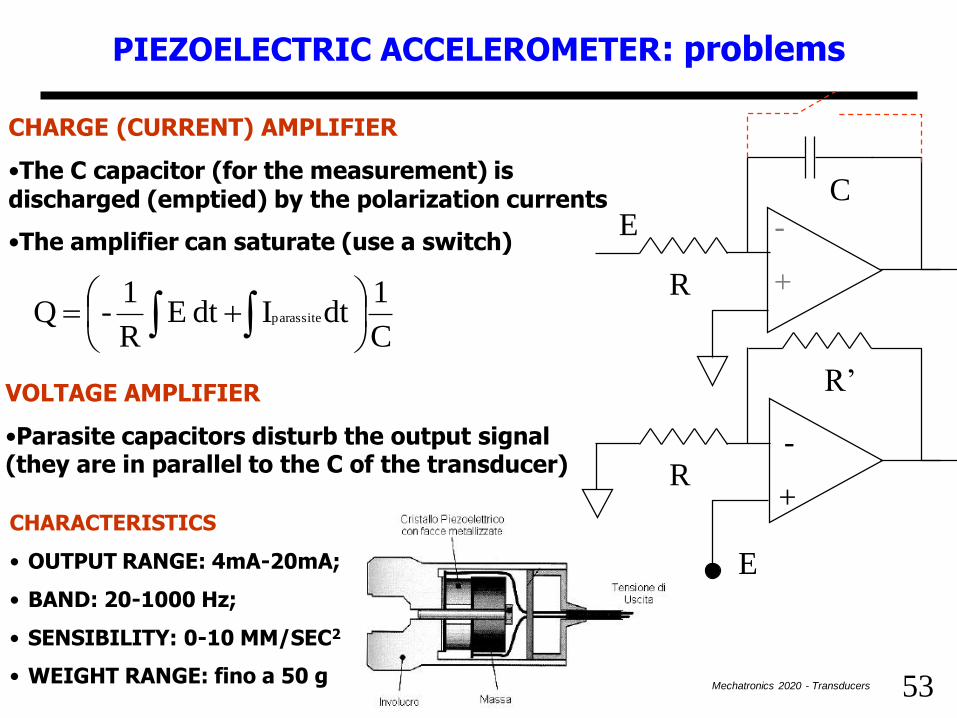
PIEZOELECTRIC ACCELEROMETER: problems
C
1dt Idt E
R
1- Q parassite
CHARGE (CURRENT) AMPLIFIER
•The C capacitor (for the measurement) is discharged (emptied) by the polarization currents
•The amplifier can saturate (use a switch)
+
-
R
CE
VOLTAGE AMPLIFIER
•Parasite capacitors disturb the output signal (they are in parallel to the C of the transducer)
CHARACTERISTICS
• OUTPUT RANGE: 4mA-20mA;
• BAND: 20-1000 Hz;
• SENSIBILITY: 0-10 MM/SEC2
• WEIGHT RANGE: fino a 50 g
R
R’
E
+
-

54Mechatronics 2020 - Transducers
• MEMSIC in MEMS technology = a system for measuring a movement made up with a silicon integrated circuit.
• MEMS (Micro-Electro-Mechanical-System) = ensemble of all those elements (sensors, actuators and electronic devices), carried out by means of a mintegration process on a silicon layer.
• If used for measuring the acceleration the range is [±1g ±100g].
• Both dynamic (vibrations) and static (gravity) accelerations.
• Resolution < mg, at least at very low frequencies.
• Available in hermetically sealed with low thickness (2 mm).
• Temperature range [-40º +105º].
MEMS ACCELEROMETERS
55Mechatronics 2020 - Transducers
• Based on the heat transfer due to spontaneous convection. It measures the change in the heat distribution due to acceleration.
• MEMSIC accelerometers are functionally equivalent to those mass-spring, but in this case the prove mass is a gas bubble.
• Great advantages compared to traditional solid mass:
–The device does not feature dead areas due to friction or other passive sources that spread energy like in other traditional transducers;
–It resists to the shock up to 50000 g with a significant reduction of
damages and less wastes during assembling.
• Convection: a thin bubble of heated gas “moves” due to external forces (accelerations, decelerations, gravity, vibrations, etc …).
• Cool air has a great density than hot one. If this one is located close to a heat source every movement or variation in the gravity makes the more dense cool air to push the hot away far from the center of the cavity.
MEMS ACC.: HOW THEY WORK
56Mechatronics 2020 - Transducers
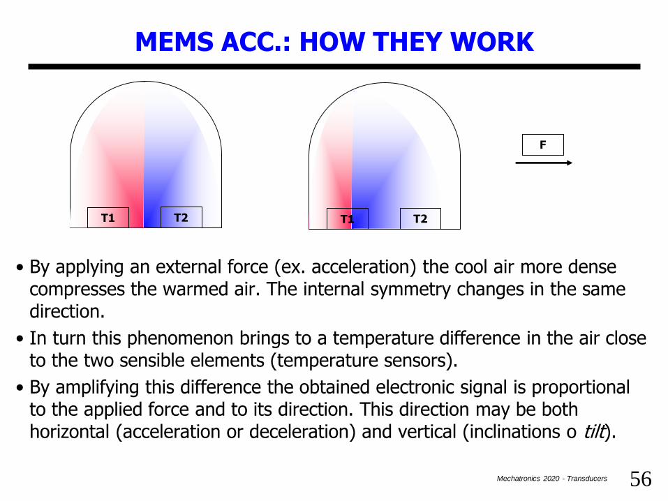
• By applying an external force (ex. acceleration) the cool air more dense compresses the warmed air. The internal symmetry changes in the same direction.
• In turn this phenomenon brings to a temperature difference in the air close to the two sensible elements (temperature sensors).
• By amplifying this difference the obtained electronic signal is proportional to the applied force and to its direction. This direction may be both horizontal (acceleration or deceleration) and vertical (inclinations o tilt).
MEMS ACC.: HOW THEY WORK
T1 T2 T1 T2
F
57Mechatronics 2020 - Transducers
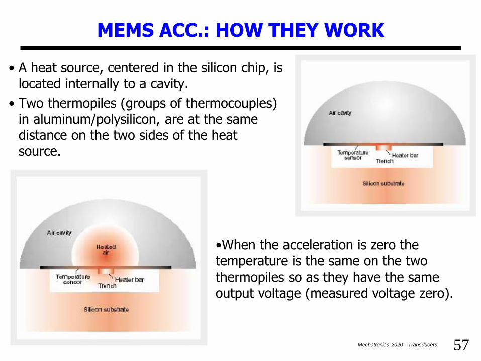
• A heat source, centered in the silicon chip, is located internally to a cavity.
• Two thermopiles (groups of thermocouples) in aluminum/polysilicon, are at the same distance on the two sides of the heat source.
MEMS ACC.: HOW THEY WORK
•When the acceleration is zero the temperature is the same on the two thermopiles so as they have the same output voltage (measured voltage zero).

58Mechatronics 2020 - Transducers
MEMS ACC.: HOW THEY WORK
• A strong acceleration will perturb the temperature profile due to the free convection of the heat making it asymmetric.
• The temperature, and therefore the voltage output, will be different in the two thermopiles.
• The asymmetric temperature profile corresponds to the moving direction
• The density of the cool air (greater) pushes the heated bubble determining a difference in the temperatures measured by the two thermopiles.
• This influences the resistances of the thermocouples in the thermopiles and this in-homogeneity produces an output proportional to the acceleration.
• In the figure the bubble displacement is shown towards right, due to the application of a deceleration or a variation of the gravity force.

59Mechatronics 2020 - Transducers
MEMS ACC.: HOW THEY WORK, SUMMARY
Not fueled Fueled stopped Fueled with
acceleration

60Mechatronics 2020 - Transducers
MEMS ACC.: GENERAL SUMMARY
Micro mechanical systems very promising for consumers electronics and sensors.
Video games console, digital images stabilizers, fall arrester sensors.
Miniaturizability wearability.
Low costs mass-market
Critical issues:
automotive:, shock resistance, temperature range, size
consumer: low power, shock resistance, reliability, size
Manufacturers:
Texas Instruments, Hewlett Packard, Bosch, ST Microelectronics, Freescale, Seiko, Lexmark.
61Mechatronics 2020 - Transducers
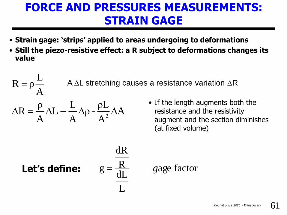
• Strain gage: ‘strips’ applied to areas undergoing to deformations
• Still the piezo-resistive effect: a R subject to deformations changes its value
FORCE AND PRESSURES MEASUREMENTS: STRAIN GAGE
AA
ρL - ρ
A
L L
A
ρ R
R una provoca L toallungamenun A
Lρ R
2DDDD
DD
• If the length augments both the resistance and the resistivity augment and the section diminishes (at fixed volume)
factor age
L
dLR
dR
g gLet’s define:
A DL stretching causes a resistance variation DR

62Mechatronics 2020 - Transducers
RdL
Lper precedente eespressionl' iamomoltiplich
FORCE AND PRESSURES MEASUREMENTS: STRAIN GAGE
L
dL
d
L
dL
d
1A
A
L -
L
ρ
AR
L
AR
Lρ
2
A
A
Lg
D
D
D
D
•An elongation makes the area A to diminish, not the volume
sezioneminor trazioneuna 0
L
dLA
dA
α-
parti)per ne(derivazio 0 AdL LdA
0AL)( 0L se AL V
DD
Let’s multiply the previous expression by
(derivation by parts)
traction implies minor section

63Mechatronics 2020 - Transducers
FORCE AND PRESSURES MEASUREMENTS: STRAIN GAGE
α
L
dL
d
1
g
•The most important term is the second one. In metals g is between 0 and 12, for semiconductors even between 100 and 200 (in this case, however, problems arise about the sensibility to the temperature).
•Used in couple of sensors (with Wheatstone bridge conditioning circuits) to compensate homologous resistance variations due to environmental factors and at the same time to highlight differential variations.
•Mounted on an elastic support not exerting opposition to the deformation.
•Horizontal and vertical deformations, forces, torques, torsions are measured.
0 a 1

64Mechatronics 2020 - Transducers
FORCE AND PRESSURES MEASUREMENTS: STRAIN GAGE
Horizontal deformation
DR0
DRv
DR0
Deformation measurement
Horizontal deformation + vertical deformation
Strain gage
F
Force measurements: two strain gages with two deformations in stretching and shrinking. With a bridge circuit the difference in the variation of the resistors is highlighted

65Mechatronics 2020 - Transducers
FORCE AND PRESSURES MEASUREMENTS: STRAIN GAGE
Torsion of a shaft measurement:
•The two strain gage measure 2 deformations due to stretching and shrinking.
•The provided values are equal but opposite in sign.
•With a Wheatstone bridge the difference in the variation of R is highlighted so increasing the sensibility of the transducer and compensating the effect of the temperature.
E1 shrinking
E2 stretching

66Mechatronics 2020 - Transducers
TEMPERATURE TRANSDUCERS
Seebeck effect = due to thermal agitation (thermo-ionic effect), free charges (electrons in metals, holes in semiconductors) can escape from the conduction band where they usually are.
If a material features extremities at different temperatures the charges diffuse from the «hot» to the «cool» one (but also viceversa) till the a thermal equilibrium is reached.
dl grad(T) k Edl V
If the difference between the temperature between the terminals is constant the flux is continuous. However the diffusion velocity of the charges is related to their energy and thus to their temperature (Richardson law).
Therefore a charge density is born at one of the extremities greater than in the other one and this creates an electric field.
The circling of the field on the conductive material provides a voltage temperature variation.

67Mechatronics 2020 - Transducers
THERMOCOUPLES
A conductor close on itself does not provide any voltage even though dV/dx are present throughout the conductor.
Where a DT>0 is present the electric field is oriented at the opposite with respect to where DT<0 the overall field is null.
The relationship between the generated voltage and the temperature variation depends on the type of material (copper, constantan, nickel-cromium).
T1
T2
T5
T3
T4
T1
T1 T2
T1T1
0dx
dT
0dx
dT
0dx
dT
Now if we use different materials, in presence of temperature gradients (T2>T1), different electric field arise and electromotive forces that do not compensate.
The consequent voltage can be related to the temperature difference (proportional, first approximation).
68Mechatronics 2020 - Transducers
THERMOCOUPLES
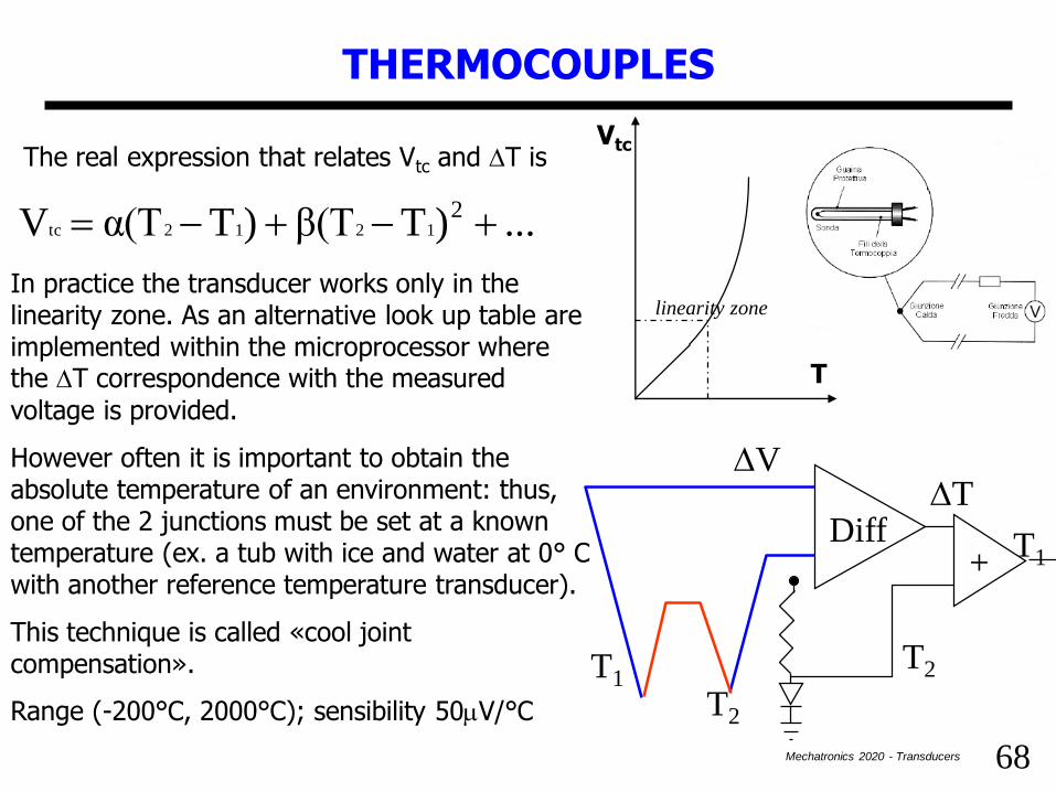
... )Tβ(T )Tα(TV
T e V trareale Relazione
21212tc
tc
D
In practice the transducer works only in the linearity zone. As an alternative look up table are implemented within the microprocessor where the DT correspondence with the measured voltage is provided.
However often it is important to obtain the absolute temperature of an environment: thus, one of the 2 junctions must be set at a known temperature (ex. a tub with ice and water at 0° C with another reference temperature transducer).
This technique is called «cool joint compensation».
Range (-200°C, 2000°C); sensibility 50mV/°C
Vtc
T
T1
T2
+
DVDT
T1Diff
T2
linearity zone
The real expression that relates Vtc and DT is
69Mechatronics 2020 - Transducers
THERMOPILES
Thermocouples are used to measure temperature variations (100°C-200°C)
Thermoresistors instead are used to keep a reference temperature
Weak output voltages (550 mV/°C) amplification and short connections
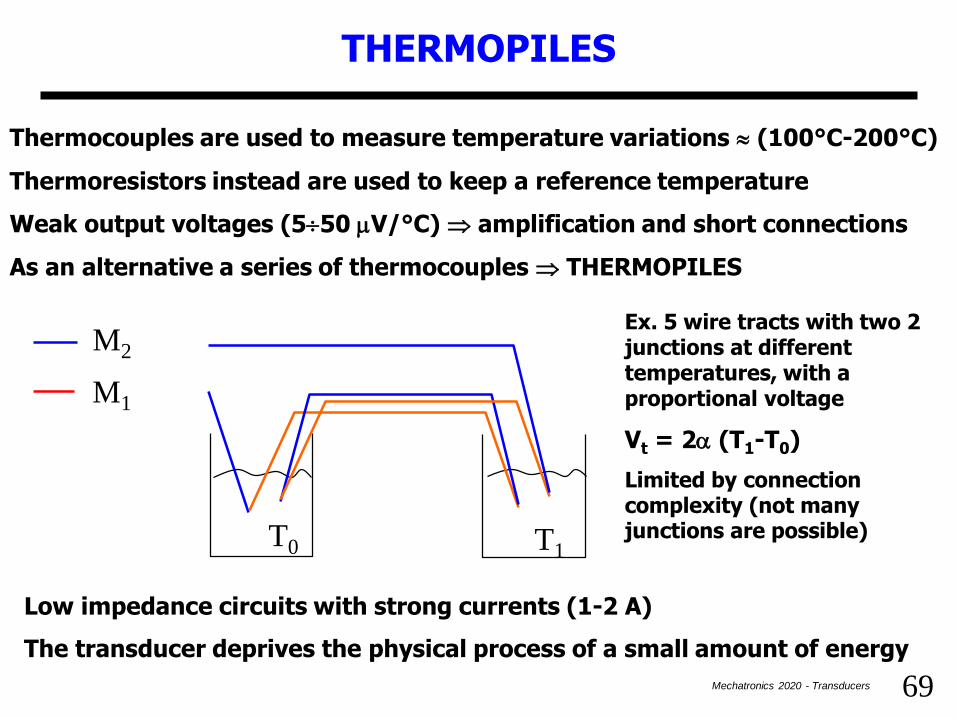
As an alternative a series of thermocouples THERMOPILES
M2
M1
T0 T1
Ex. 5 wire tracts with two 2 junctions at different temperatures, with a proportional voltage
Vt = 2a (T1-T0)
Limited by connection complexity (not many junctions are possible)
Low impedance circuits with strong currents (1-2 A)
The transducer deprives the physical process of a small amount of energy

70Mechatronics 2020 - Transducers
THERMORESISTANCES AND THERMISTORS
Here the temperature – resistance conversion is exploited: in thermo-resistances, depending on the used metal, the temperature variation can affect the electrons average path (reduces) so as modifying the resistance of a conductive material.
If semiconductors are used (thermistors) charge modulation must be taken into account (they augment if T is increased), that prevail in the R determination.
These effects are present in the two material classes called: PTC e NTC
PTC (positive temperature coefficient)
Collisions between free electrons and crystal lattice: >T , >resistance
R = R0 (1+a(T-T0)) per T= T0 R = R0 a = dR/(R0 dT)
• a positive and dependent on T and on the material (for Platinum at 0°C is 0.0038)
• it is also possible to write R = R0 (1+a(T-Tk0)) = R0 (1+(T-Tk0)/Tk0) = R0 (T/Tk0) linear
relation between the absolute T if a =1/Tk0 (Kelvin) => thermometer
• PTC linear in typical temperature ranges (PT100 works between 0 and 100°)
• good sensibility if compared to, for example, strain gages
71Mechatronics 2020 - Transducers
THERMORESISTANCES AND THERMISTORS
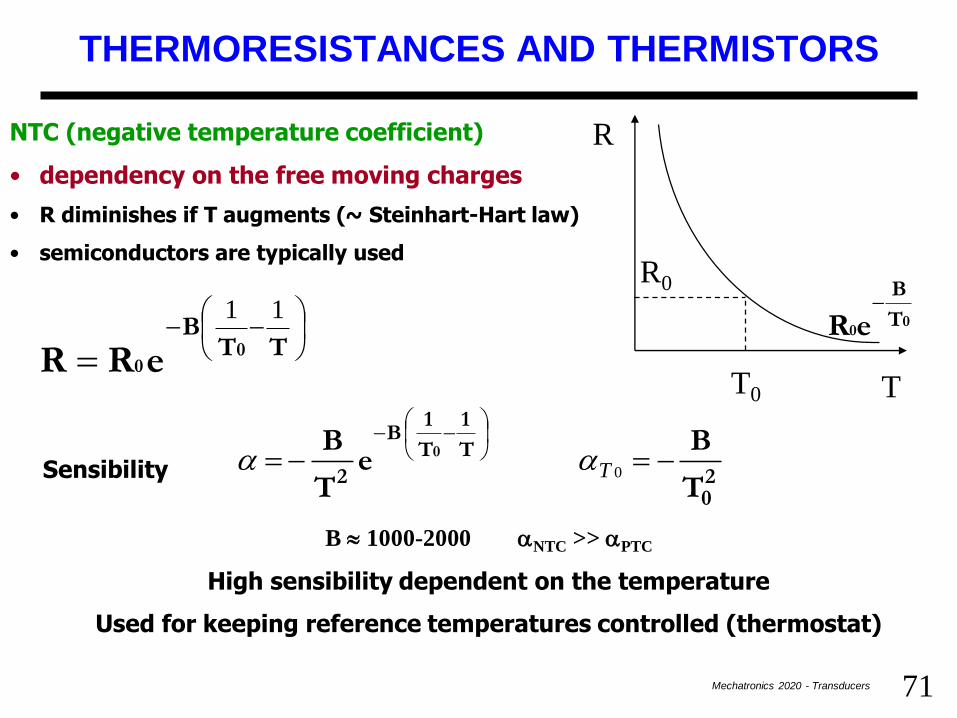
NTC (negative temperature coefficient)
• dependency on the free moving charges
• R diminishes if T augments (~ Steinhart-Hart law)
• semiconductors are typically used
R
T
00
T
B
eR
T0
R0
TTB
0 0eRR
11
20
T
1
T
1 B
2 T
B e
T
B àSensibilit 0
0Taa
B 1000-2000 aNTC >> aPTC
High sensibility dependent on the temperature
Used for keeping reference temperatures controlled (thermostat)
Sensibility

72Mechatronics 2020 - Transducers
THERMORESISTANCES AND THERMISTORS
NTC are very often employed to monitor continuously the temperature.
These sensors feature a sensibility very higher than thermo-resistanceswithout any further electronic circuits since their SNR is very high (due tothe high sensibility) and the parasite effect of the connection cables can beneglected.
Conversely in case of large variations in temperature, NTC thermistors aregreatly un-linear, therefore it is necessary correction circuits, or Look-Up-Tables for linearization or to perform suitable numerical interpolationstrough microprocessor running code.
PTC sensors work in a more reduced interval and are typically used toprotect devices and circuits by overloads and thermal shocks due to over-heating. In this case, thanks to the high gain and to their thresholdanswer, they are provided with a logic output circuit to signal theexceeding of a predefined temperature.
PTCs work as detectors of thermal threshold coupled with suitablecalibrated comparators.
73Mechatronics 2020 - Transducers
INTEGRATED TEMPERATURE TRANSDUCERS
D 1KT/e
VD
D0D
1
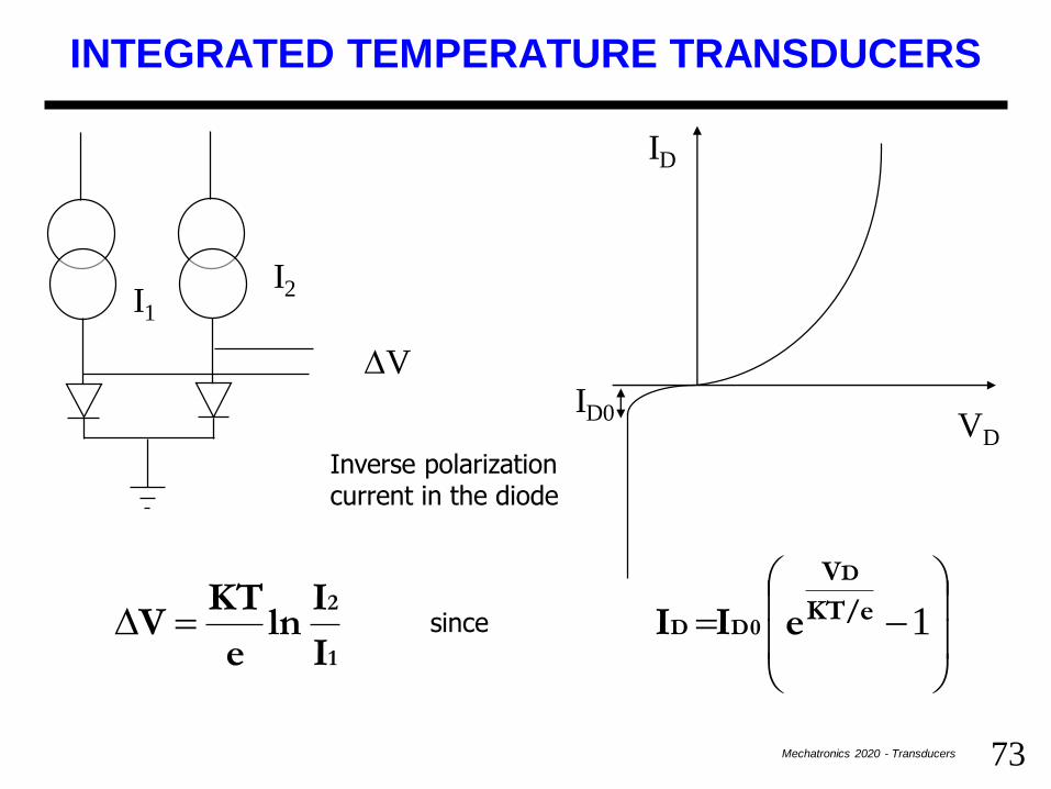
2e I I che essendo
I
Iln
e
KTV
ID
VD
I2I1
DVID0
corrente di polarizzazione
inversa del diodo
Inverse polarization current in the diode
since

74Mechatronics 2020 - Transducers
PRESSURE TRANSDUCERS
They are based on the conversion of the pressure in the deformation of a foil mounted on a suitable «proof chamber».
P P0
Two strain gages mounted in the center of one of the walls, measure opposite deformations Wheatstone bridge
Calibration: a known pressure is applied to the system to determine the coefficient between the pressure and the unitary deformation
Daisy petal strain gages to measure spherical
deformations
A transducer is screwed through
filleting to the chamber into which
the pressure must be measured
75Mechatronics 2020 - Transducers
PRESSURE TRANSDUCERS
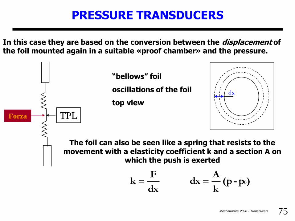
In this case they are based on the conversion between the displacement of the foil mounted again in a suitable «proof chamber» and the pressure.
“bellows” foil
oscillations of the foil
top view
The foil can also be seen like a spring that resists to the movement with a elasticity coefficient k and a section A on
which the push is exerted
TPL
)p-(p k
Adx
dx
Fk 0
Forza
dx
76Mechatronics 2020 - Transducers
PRESSURE TRANSDUCERS
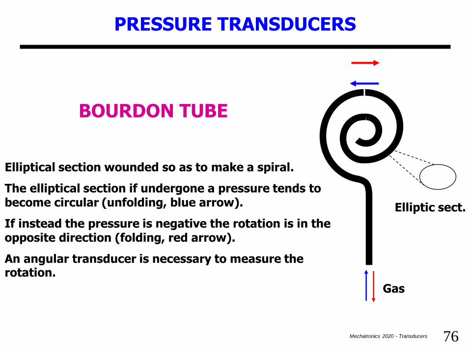
BOURDON TUBE
Elliptical section wounded so as to make a spiral.
The elliptical section if undergone a pressure tends to become circular (unfolding, blue arrow).
If instead the pressure is negative the rotation is in the opposite direction (folding, red arrow).
An angular transducer is necessary to measure the rotation.
Elliptic sect.
Gas

77Mechatronics 2020 - Transducers
FLOW-METERS
• Within a tube into which a stream flows a mass flow rate Fm
and a volume flow rate Fv
(constant volume)
• Fm = dm/dt = infinitesimal quantity of mass of fluid that flows in a time dt in the tube section.
• Fv = dv/dt = infinitesimal quantity of mass of fluid that flows in a time dt in the tube section.
• Fm = d Fv d = dm/dv
• Notice that for the gas the volume changes depending on the pressure (> compressibility)
• The easiest measurement is Fv that is obtained through a velocity
• Fv = A vm vm= average vel. media A = effective sect.
• Il the flow meter is coupled with a pressure transducer (from which the density can be achieved by means of the Bernoulli law), we have a mass flow-meter.
• We only deal with volumetric flow-meters (by hypothesis we work at constant volume)

78Mechatronics 2020 - Transducers
TURBO FLOW METER
• f = a vm vm= average velocity a = turbine charact.f = rotation frequency
• We can guess that f = b Fv so since Fv = A vm
b = a/A
• b dimensions are 1/vol.
• By measuring fluid quantity that moves with the turbine we obtain b ; f can be measured with a dynamo.
Problems:
•the turbine can disturb the flow so altering the measurement and this depend on the viscosity and density of the fluid
•Viscosity and density affect also b
v
79Mechatronics 2020 - Transducers
ELECTROMAGNETIC FLOWMETER
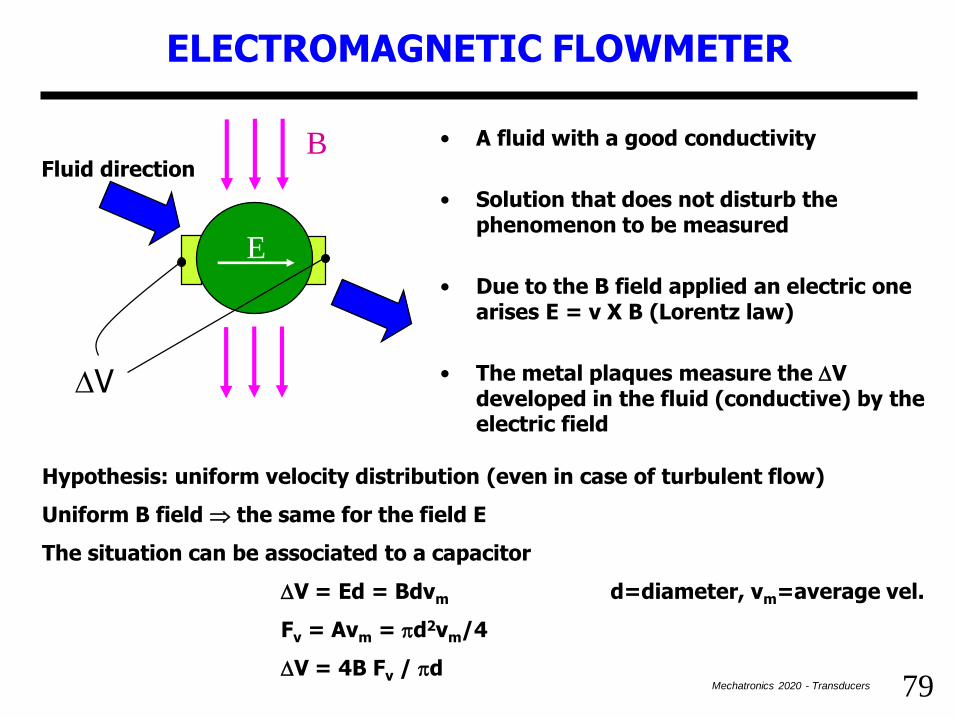
• A fluid with a good conductivity
• Solution that does not disturb the phenomenon to be measured
• Due to the B field applied an electric one arises E = v X B (Lorentz law)
• The metal plaques measure the DV developed in the fluid (conductive) by the electric field
Fluid direction
E
DV
B
Hypothesis: uniform velocity distribution (even in case of turbulent flow)
Uniform B field the same for the field E
The situation can be associated to a capacitor
DV = Ed = Bdvm d=diameter, vm=average vel.
Fv = Avm = pd2vm/4
DV = 4B Fv / pd

80Mechatronics 2020 - Transducers
ELECTROMAGNETIC FLOWMETER
•Considering the average velocity is a strong appproximation (true only if the velocity distribution is cylindrical).
•The transducer produces a current and this deprives energy to the flow (slightly slower than if not measured).
•Need for accurate electrodes to avoid contact voltages that alter the measure. It is possible to avoid this by odulating the field B using AC power supply. The eventual contact voltage is easily cancelled.
•The output is in phase or counterphase with the power supply depending on the direction of the fluid. A synchronous rectifier is required.
•Useful pattern since without mechanical parts (like as the turbine)

81Mechatronics 2020 - Transducers
ULTRASOUND FLOWMETER
FLOW
TR1 TR2Ultrasound propagation chamber with generators/receivers on two sides
The emission of a US beam from TR1 is perceived by TR2 in a time t12
vc essendo c
2vL
vc
2vL
vc
1
vc
1 L tt
camera lunghezza L vc
L t
liquido vel. ultrasuoni . velvc vc
L t
222 12 - 21
21
12
L
ULTRASOUND + LIQUID VELOCITIES
L chamber length
where c>>v
82Mechatronics 2020 - Transducers
VENTURI TUBE (VENTURIMETER)
P1
P2
D dv1 v2
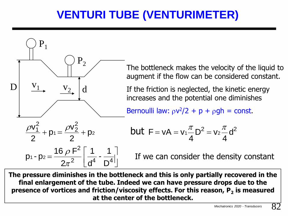
The bottleneck makes the velocity of the liquid to augment if the flow can be considered constant.
If the friction is neglected, the kinetic energy increases and the potential one diminishes
Bernoulli law: v2/2 + p + gh = const.
densità la costante supponendo D
1 -
d
1
2
F 16 p - p
d4
v D4
v vA F ma p 2
vp
2
v
442
2
2222
21
21
21 2 1
p
pp
The pressure diminishes in the bottleneck and this is only partially recovered in the final enlargement of the tube. Indeed we can have pressure drops due to the
presence of vortices and friction/viscosity effects. For this reason, P2 is measured at the center of the bottleneck.
If we can consider the density constant
but

83Mechatronics 2020 - Transducers
LEVEL-METERS
+
A first solution can be given by a float element connected to a pulley with an angular position transducer.
The wire/rope must be always tensed and the weight constant.
T h
A second option exploits a ultrasound generator on the bottom of tub: the US beam is reflected by the water edge and the echo is received after a time
t=2h/c
c can depend on the liquid temperature. To break out from this, an intermediate path can be introduced with a fixed obstacle located at a known height. The obstacle reflects part of the US beam so as
h=hr t/tr
hrh

84Mechatronics 2020 - Transducers
RESISTIVE AND CAPACITIVE LEVEL-METERS
h
2 armors merged in a container to allow resistive or capacitive measurements
If a conductive liquid is used the resistance measure is performed at low-medium frequencies while at high ones a capacitive one is performed so as to neglect the resistive contribute in parallel to the capacitor.
L
d
( )d
ee
de
eee
dd
hL1-
LHC
elettrodi) altezza (H h)L-(H ALh Aδ
A
δ
AC
CAPACITA' DIMISURA
immersa) e(superfici Lh A Lh
A
R
RESISTENZA DI MISURA
11
r
r
00
00
RESISTIVE MEASUREMENT
CAPACITIVE MEASUREMENT
(merged surface)
(H electrodes height)

85Mechatronics 2020 - Transducers
ACIDITY MEASUREMENT (PH-METER)
Acid and basic solutions dissociate in water in positive and negative ions. Mainly H+
ions if acid, OH- ions otherwise.
Water itself undergoes the same phenomenon but it is conventionally considered electrically balanced with a H+ ions concentration equal to 1 every 10 million molecules (10-7).
If an acid substance is introduced the quantity of H+ ions increases while the OH-
diminishes and viceversa if a basic substance is added.
pH=-log [H+] is defined as the index that measures the acidity of a solution.
In case of neutral solution pH=7, if it is basic pH=14, if acid pH=0.
A pH-meter is a scientific instrument made of a recipient with two electrodes of which one is merged in reference buffer solution.
The measurement corresponds to the DV due to the surface contact between the two electrodes and the liquids (buffer solution + substance under analysis. The electrodes provide a potential constant for the reference solution and depending on the ion concentration for the analyzed substance
86Mechatronics 2020 - Transducers
ACIDITY MEASUREMENT (PH-METER)
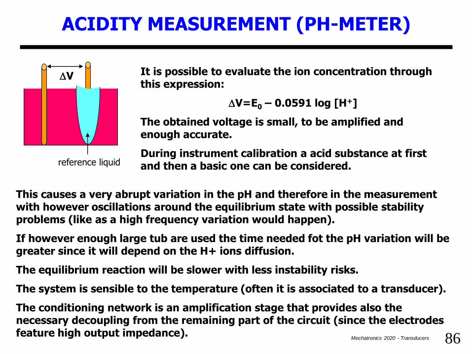
It is possible to evaluate the ion concentration through this expression:
DV=E0 – 0.0591 log [H+]
The obtained voltage is small, to be amplified and enough accurate.
During instrument calibration a acid substance at first and then a basic one can be considered.reference liquid
DV
This causes a very abrupt variation in the pH and therefore in the measurement with however oscillations around the equilibrium state with possible stability problems (like as a high frequency variation would happen).
If however enough large tub are used the time needed fot the pH variation will be greater since it will depend on the H+ ions diffusion.
The equilibrium reaction will be slower with less instability risks.
The system is sensible to the temperature (often it is associated to a transducer).
The conditioning network is an amplification stage that provides also the necessary decoupling from the remaining part of the circuit (since the electrodes feature high output impedance).