Embed Size (px)
DESCRIPTION
Lecture items. Compositions of the Uphole- Downhole Instruments. Field Operation (Data Acquisition, Processing and Transmission) Log Runs Borehole Environment opposite a Permeable Zone. Structure of a Log head. Recording Format Images logs Basic reservoir characteristics. - PowerPoint PPT Presentation
Citation preview

Lecture itemsLecture items- Compositions of the Uphole- Downhole
Instruments.- Field Operation (Data Acquisition, Processing
and Transmission)- Log Runs - Borehole Environment opposite a Permeable
Zone.- Structure of a Log head.- Recording Format- Images logs- Basic reservoir characteristics

Compositions of the Uphole- Compositions of the Uphole- Downhole InstrumentsDownhole Instruments..
Uphole Instruments include the Logging Truck and the Rig. The logging Truck mainly consists of mechanical Winches and ordinary driving machine.
Downhole Instruments are represented by Cables and Sondes. Sondes differ in function from measurement to another based on the
required physical property to be measured (GR , Resistivity, Neutron, Sonic, Density, Magnetic, Thermal, etc)
Sonde normally consists of two main parts:- Sensor: It is an electronically complicated part used for picking the
required property. It is usually shielded with fibers in the modern tools.
- Cartridge: Surrounding the sensor in the modern tools and do three functions:
- * Powering the sensor to be ON/OFF .- * Processing the acquired data (First step of processing).- * Data transmission along cables to the up-hole instruments.

Modern CableModern Cable
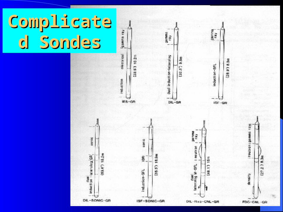
Complicated Complicated SondesSondes

Field OperationField Operation Data Acquisition (by Sondes)Data Processing (Three steps)Data Transmission (Two stages)

Data TransmissionData Transmission
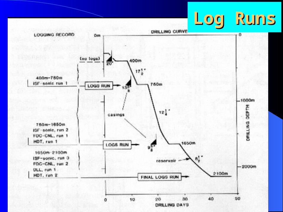
Log RunsLog Runs
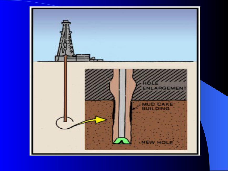
Borehole EnvironmentBorehole EnvironmentWhen a hole is drilled into a formation, the
rock and the fluids in it (rock-fluid system) are altered in the vicinity of the borehole. A well’s borehole and the rock surrounding it are contaminated by the drilling mud, which affects logging measurements. Figure 1 is a schematic illustration of a porous and permeable formation which is penetrated by a borehole filled with drilling mud.

Borehole Borehole EnvironEnviron
mentment

Borehole EnvironmentBorehole Environment
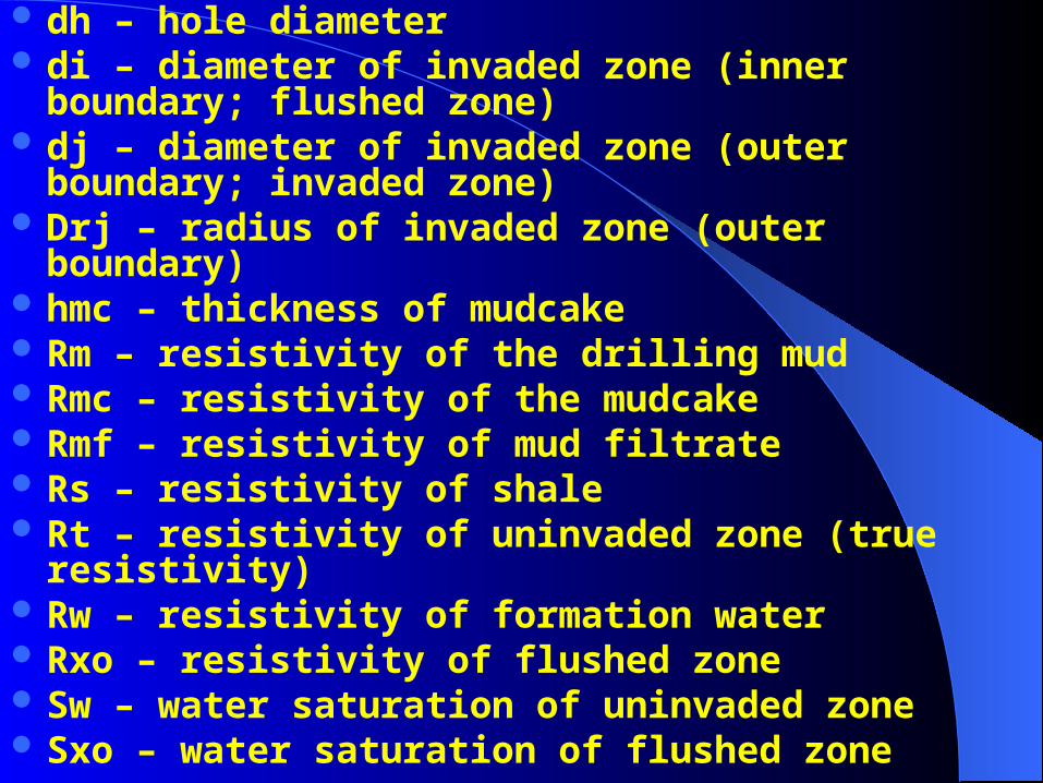
dh – hole diameter di – diameter of invaded zone (inner boundary; flushed
zone) dj – diameter of invaded zone (outer boundary; invaded
zone) Drj – radius of invaded zone (outer boundary) hmc – thickness of mudcake Rm – resistivity of the drilling mud Rmc – resistivity of the mudcake Rmf – resistivity of mud filtrate Rs – resistivity of shale Rt – resistivity of uninvaded zone (true resistivity) Rw – resistivity of formation water Rxo – resistivity of flushed zone Sw – water saturation of uninvaded zone Sxo – water saturation of flushed zone

Invasion Invasion ProfileProfile
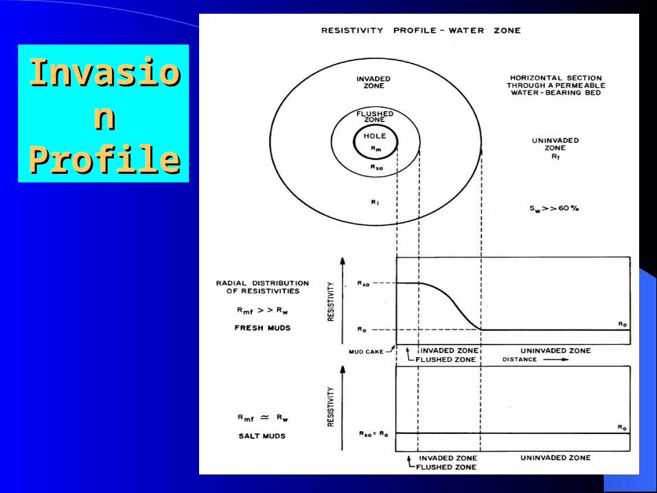
Invasion Invasion ProfileProfile

Invasion Invasion ProfileProfile

An annulus profile is often recorded on a log because it rapidly dissipates in a well. The annulus profile is detected only by an induction log run soon after a well is drilled. However, it is very important to a geologist because the profile can only occur in zones which bear hydrocarbons. As the mud filtrate invades the hydrocarbon-bearing zone, hydrocarbons move out first. Next, formation water is pushed out in front of the mud filtrate forming an annular (circular) ring at the edge of the invaded zone. The annulus effect is detected by a relatively lower resistivity values.
Annulus zoneAnnulus zone
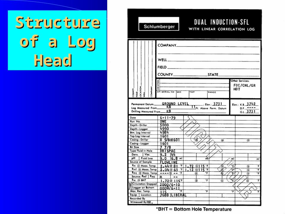
Structure of Structure of a Log Head a Log Head

Recording FormatsRecording Formats
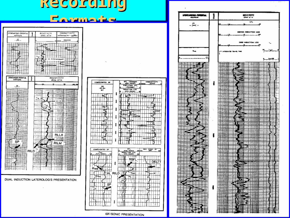
Recording FormatsRecording Formats
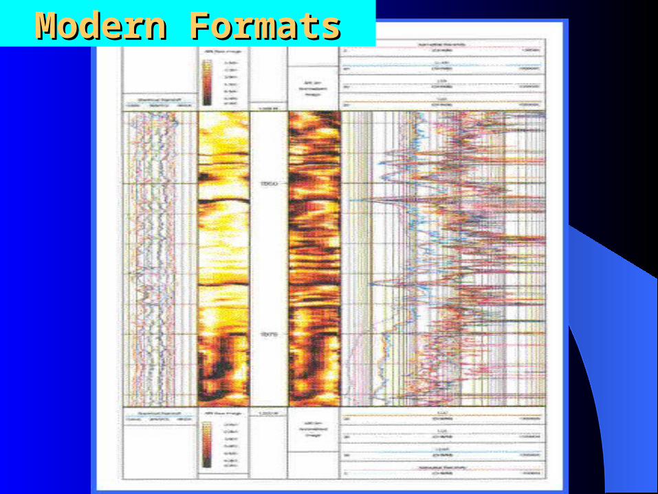
Modern FormatsModern Formats
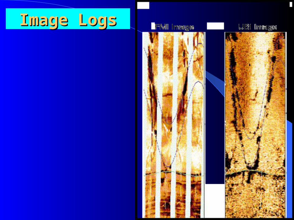
Image LogsImage Logs

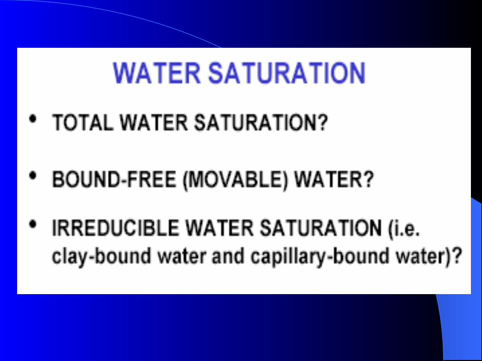
Basic reservoir characteristicsBasic reservoir characteristics
Porosity,φ (Total, effective, primary, secondary and intercrystalline)
Permeability (K) (Absolute, relative)Saturation (S) (Sw, Sxo, Sh, So, Sg,
Shr, Shm) and their interrelationships.
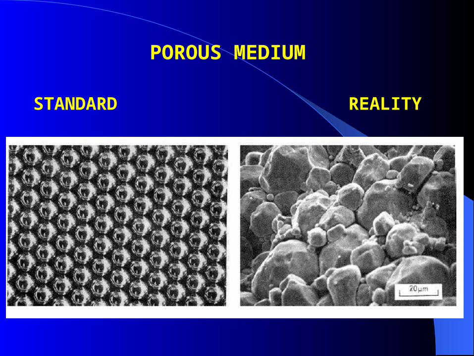
POROUS MEDIUM
STANDARD REALITY
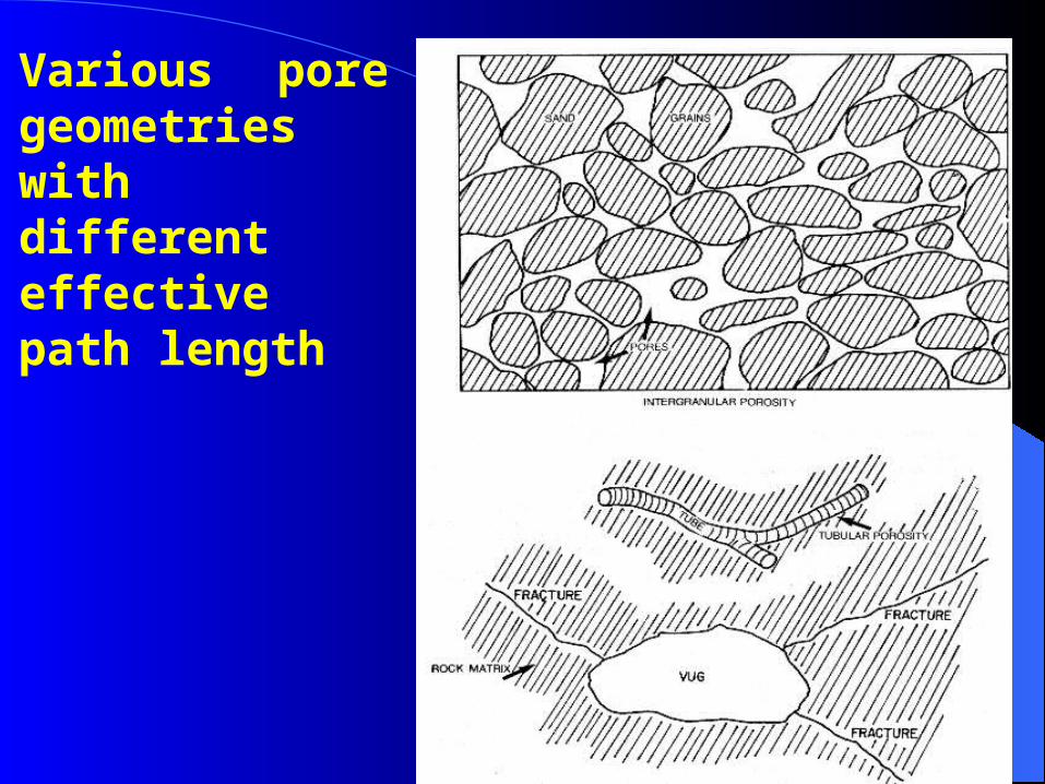
Various pore geometries with different effective path length
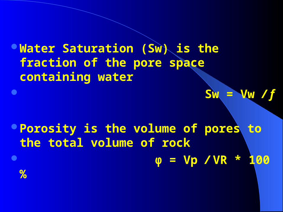
Water Saturation (Sw) is the fraction of the pore space containing water
Sw = Vw / f
Porosity is the volume of pores to the total volume of rock
φ = Vp / VR * 100 %