Embed Size (px)
Citation preview
Plantwide Control Course
Lecture 8: GTL case studySOC with more than one unconstrained DOFs
by: Mehdi Panahi
Department of Chemical Engineering Ferdowsi University of Mashhad
Plantwide Control Course, Ferdowsi University of Mashhad, M. Panahi
Mode I: maximize efficiency
Mode II: maximize throughput
Optimal Operation
Self-optimizing control is when we can achieve acceptable loss with constant setpoint values for the controlled variables without the need to reoptimize the plant when disturbances occur
Plantwide Control Course, Ferdowsi University of Mashhad, M. Panahi

Selection of CVs: Self-optimizing control procedure
Step 3-1: Define an objective function and constraints
Step 3-2: Degrees of freedom (DOFs)
Step 3-3: Disturbances
Step 3-4: Optimization (nominally and with disturbances)
Step 3-5: Identification of controlled variables (CVs) for
unconstrained DOFs
Step 3-6: Evaluation of loss
Plantwide Control Course, Ferdowsi University of Mashhad, M. Panahi
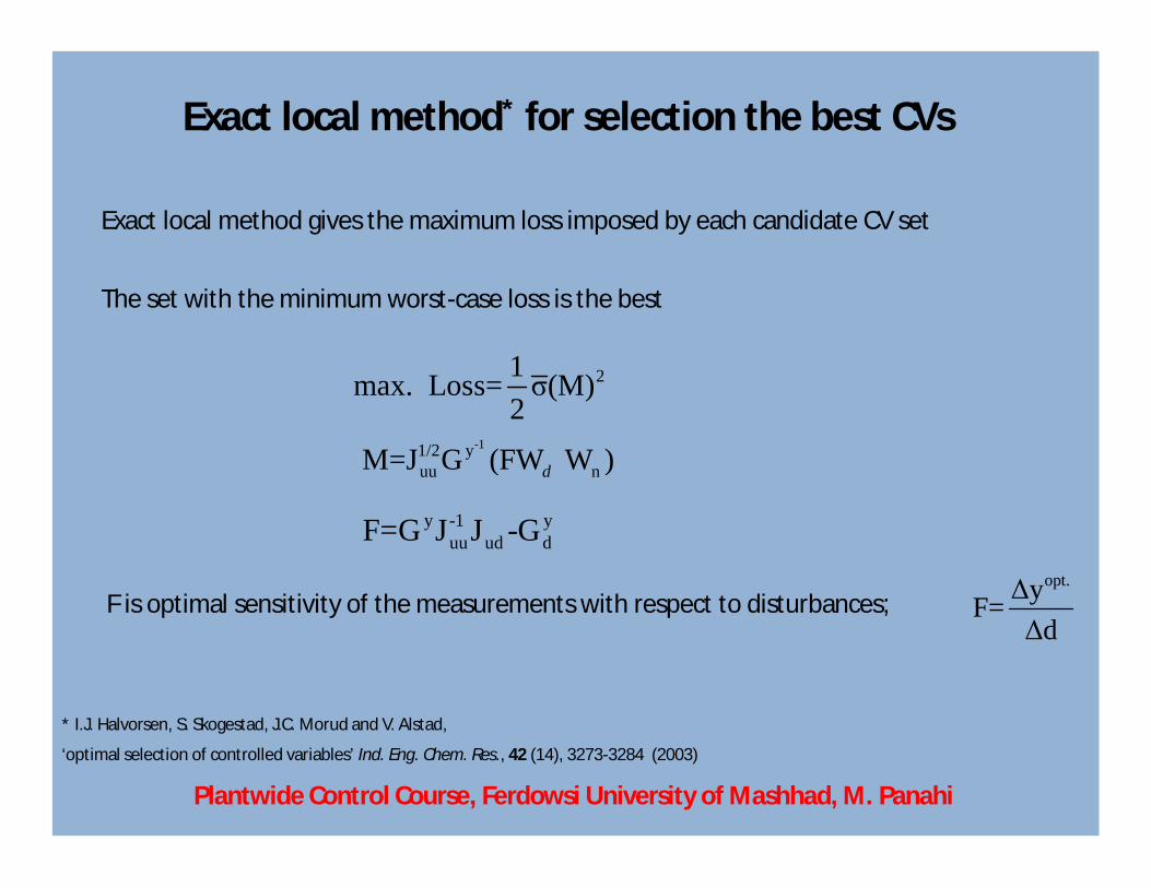
Exact local method* for selection the best CVs
Exact local method gives the maximum loss imposed by each candidate CV set
The set with the minimum worst-case loss is the best
21max. Loss= σ(M)2
-11/2 yuu nM=J G (FW W )d
y -1 yuu ud dF=G J J -G
opt.ΔyF=Δd
* I.J. Halvorsen, S. Skogestad, J.C. Morud and V. Alstad,
‘optimal selection of controlled variables’ Ind. Eng. Chem. Res., 42 (14), 3273-3284 (2003)
F is optimal sensitivity of the measurements with respect to disturbances;
Plantwide Control Course, Ferdowsi University of Mashhad, M. Panahi

A simple flowsheet of GTL process*
* Rostrup-Nielsen, J., I. Dybkjaer, et al. (2000). "Synthesis gas for large scale Fischer-Tropsch synthesis." American Chemical Society, Division of Petroleum Chemistry, Preprints 45(2): 186-189
CH4 CO+H2(CH2)n
CO+H2+CH4
CO2
(CH2)n
Plantwide Control Course, Ferdowsi University of Mashhad, M. Panahi
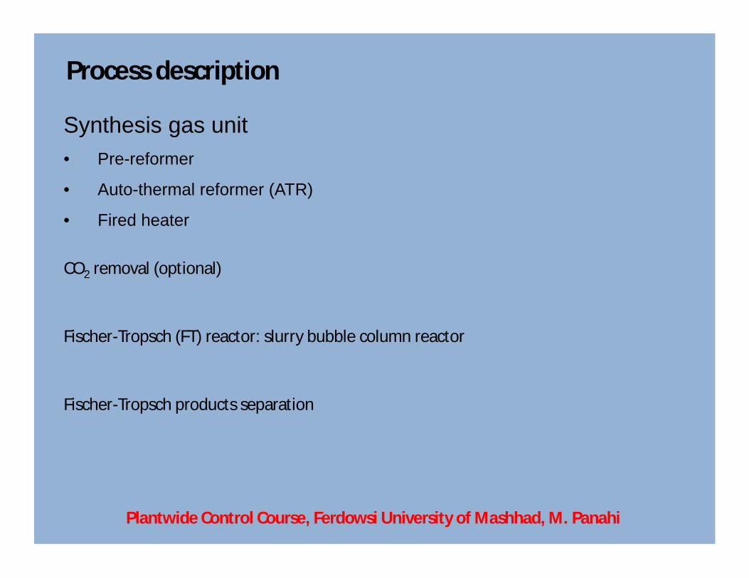
Process description
Synthesis gas unit• Pre-reformer
• Auto-thermal reformer (ATR)
• Fired heater
CO2 removal (optional)
Fischer-Tropsch (FT) reactor: slurry bubble column reactor
Fischer-Tropsch products separation
Plantwide Control Course, Ferdowsi University of Mashhad, M. Panahi

Detailed flowsheet of GTL process (UniSim)
Plantwide Control Course, Ferdowsi University of Mashhad, M. Panahi
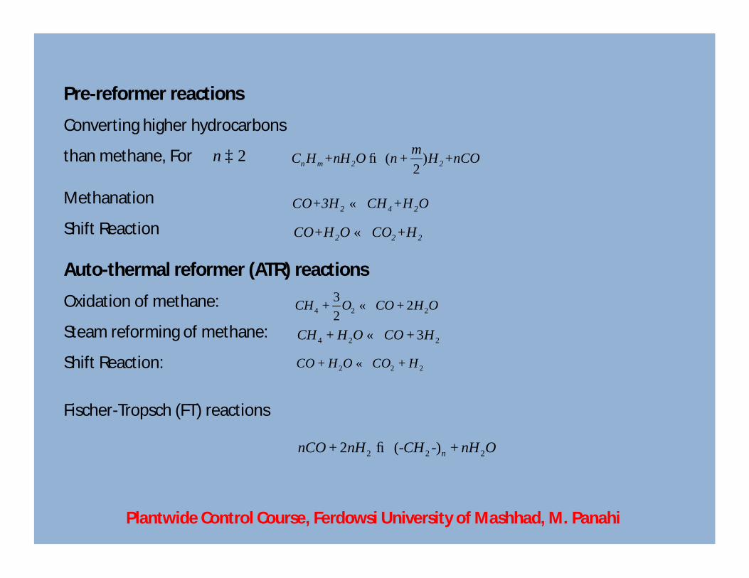
Auto-thermal reformer (ATR) reactions
2n ³
Oxidation of methane:
Steam reforming of methane:
Shift Reaction:
4 2 23 22
CH O CO H O+ « +
4 2 23CH H O CO H+ « +
2 2 2CO H O CO H + « +
( )2n m 2 2mC H +nH O n H +nCO® +
2 4 2CO+3H CH +H O«
2 2 2CO+H O CO +H«
Pre-reformer reactions
Converting higher hydrocarbons
than methane, For
Methanation
Shift Reaction
Fischer-Tropsch (FT) reactions
2 2 22 (- -)nnCO nH CH nH O+ ® +
Plantwide Control Course, Ferdowsi University of Mashhad, M. Panahi
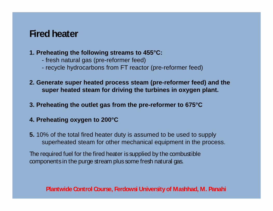
Fired heater
1. Preheating the following streams to 455°C:- fresh natural gas (pre-reformer feed) - recycle hydrocarbons from FT reactor (pre-reformer feed)
2. Generate super heated process steam (pre-reformer feed) and the super heated steam for driving the turbines in oxygen plant.
3. Preheating the outlet gas from the pre-reformer to 675°C
4. Preheating oxygen to 200°C
5. 10% of the total fired heater duty is assumed to be used to supply superheated steam for other mechanical equipment in the process.
The required fuel for the fired heater is supplied by the combustible components in the purge stream plus some fresh natural gas.
Plantwide Control Course, Ferdowsi University of Mashhad, M. Panahi
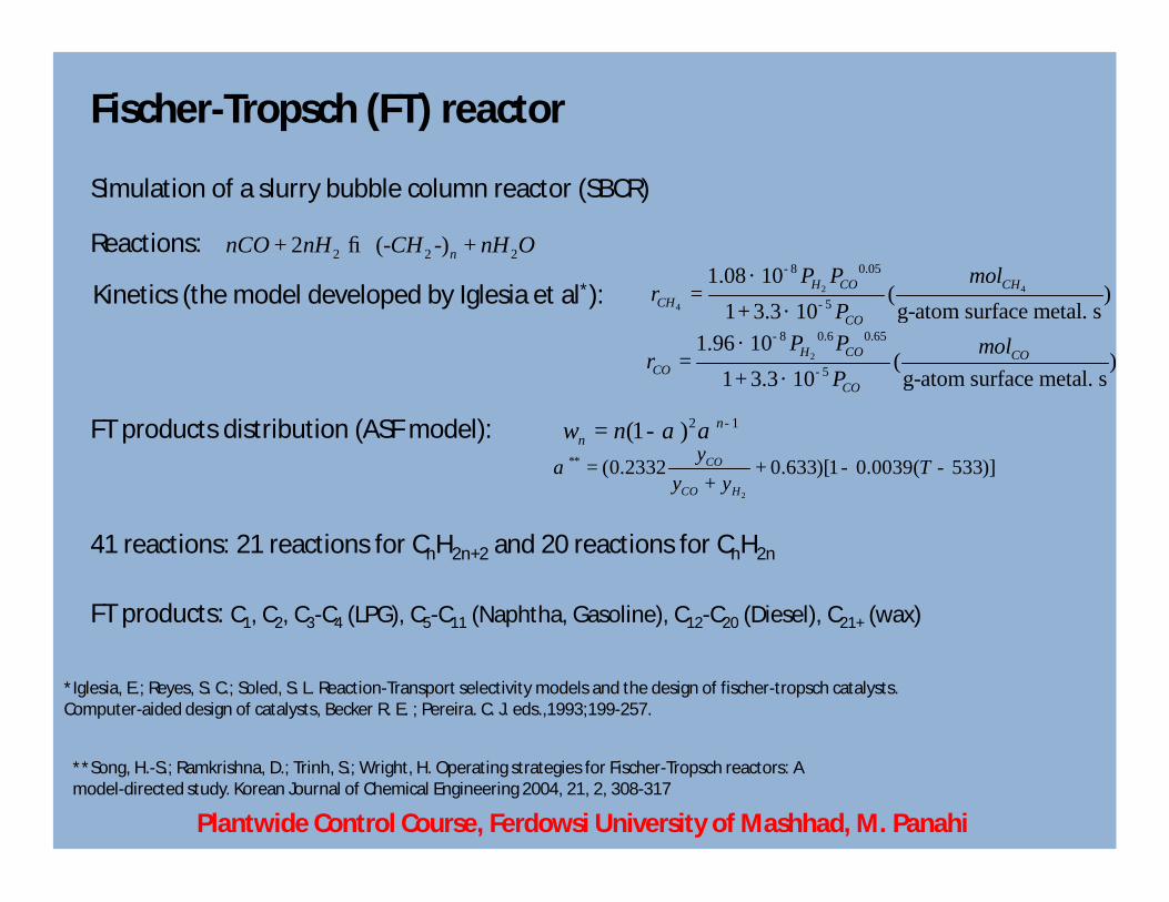
Fischer-Tropsch (FT) reactor
2 2 22 (- -)nnCO nH CH nH O+ ® +
Simulation of a slurry bubble column reactor (SBCR)
Reactions:
Kinetics (the model developed by Iglesia et al*): 2 4
4
8 0.05
5
1.08 10( )g-atom surface metal. s1 3.3 10
H CO CHCH
CO
P P molr
P
-
-
´=
+ ´
2
8 0.6 0.65
5
1.96 10( )g-atom surface metal. s1 3.3 10
H CO COCO
CO
P P molr
P
-
-
´=
+ ´
FT products distribution (ASF model): 2 1(1 ) nnw n a a -= -
2
** (0.2332 0.633)[1 0.0039( 533)]CO
CO H
y Ty y
a = + - -+
*Iglesia, E.; Reyes, S. C.; Soled, S. L. Reaction-Transport selectivity models and the design of fischer-tropsch catalysts. Computer-aided design of catalysts, Becker R. E. ; Pereira. C. J. eds.,1993;199-257.
**Song, H.-S.; Ramkrishna, D.; Trinh, S.; Wright, H. Operating strategies for Fischer-Tropsch reactors: A model-directed study. Korean Journal of Chemical Engineering 2004, 21, 2, 308-317
41 reactions: 21 reactions for CnH2n+2 and 20 reactions for CnH2n
FT products: C1, C2, C3-C4 (LPG), C5-C11 (Naphtha, Gasoline), C12-C20 (Diesel), C21+ (wax)
Plantwide Control Course, Ferdowsi University of Mashhad, M. Panahi
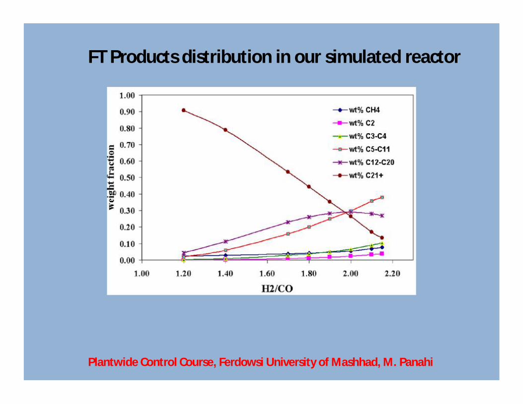
FT Products distribution in our simulated reactor
Plantwide Control Course, Ferdowsi University of Mashhad, M. Panahi
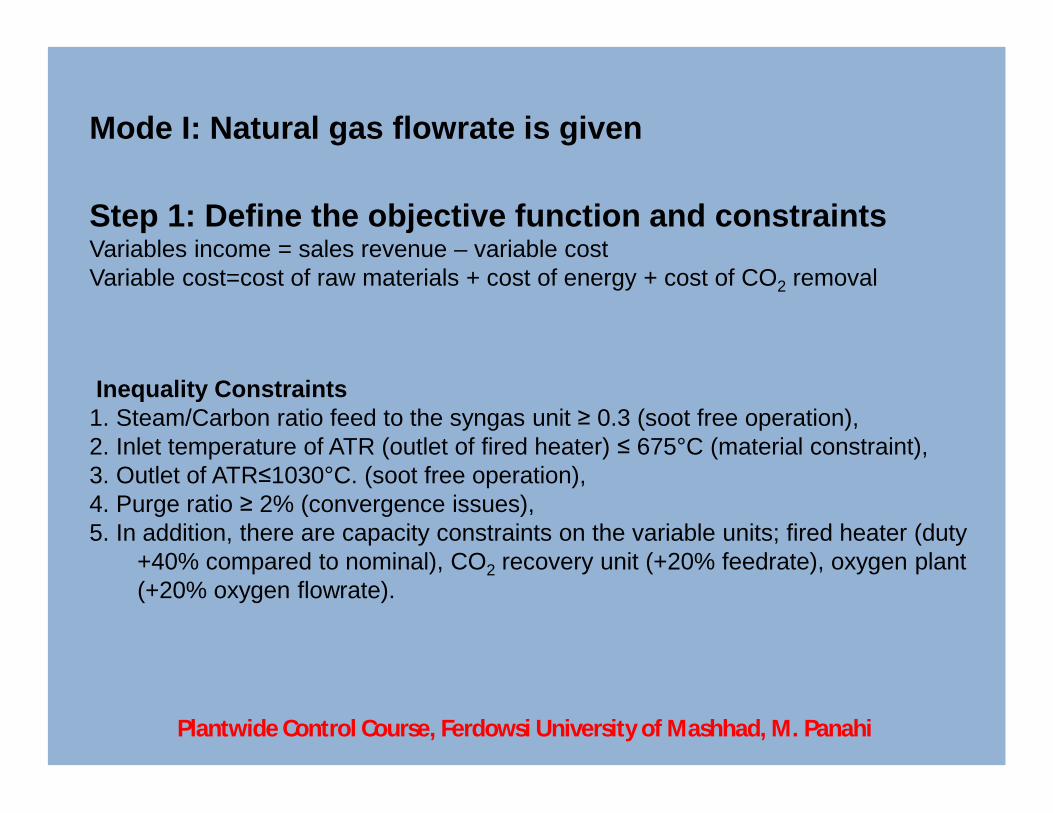
Mode I: Natural gas flowrate is given
Step 1: Define the objective function and constraintsVariables income = sales revenue – variable costVariable cost=cost of raw materials + cost of energy + cost of CO2 removal
Inequality Constraints1. Steam/Carbon ratio feed to the syngas unit ≥ 0.3 (soot free operation), 2. Inlet temperature of ATR (outlet of fired heater) ≤ 675°C (material constraint),3. Outlet of ATR≤1030°C. (soot free operation),4. Purge ratio ≥ 2% (convergence issues),5. In addition, there are capacity constraints on the variable units; fired heater (duty
+40% compared to nominal), CO2 recovery unit (+20% feedrate), oxygen plant (+20% oxygen flowrate).
Plantwide Control Course, Ferdowsi University of Mashhad, M. Panahi
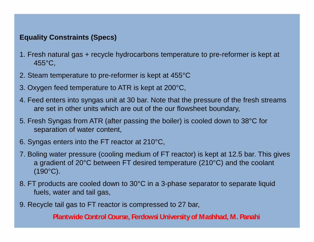
Equality Constraints (Specs)
1. Fresh natural gas + recycle hydrocarbons temperature to pre-reformer is kept at 455°C,
2. Steam temperature to pre-reformer is kept at 455°C
3. Oxygen feed temperature to ATR is kept at 200°C,
4. Feed enters into syngas unit at 30 bar. Note that the pressure of the fresh streams are set in other units which are out of the our flowsheet boundary,
5. Fresh Syngas from ATR (after passing the boiler) is cooled down to 38°C for separation of water content,
6. Syngas enters into the FT reactor at 210°C,
7. Boling water pressure (cooling medium of FT reactor) is kept at 12.5 bar. This gives a gradient of 20°C between FT desired temperature (210°C) and the coolant (190°C).
8. FT products are cooled down to 30°C in a 3-phase separator to separate liquid fuels, water and tail gas,
9. Recycle tail gas to FT reactor is compressed to 27 bar,
Plantwide Control Course, Ferdowsi University of Mashhad, M. Panahi

Step 2: Identify degrees of freedom (DOFs) for optimization
1. H2O (superheat steam) feedrate to pre-reformer (H2O/C),
2. Superheat steam bypass stream flowrate,
3. Natural gas feedrate as fuel (make up) to the fired heater,
4. Natural gas + recycle hydrocarbons bypass stream flowrate,
5. Oxygen feedrate to ATR,
6. Oxygen bypass stream flowrate,
7. Separator duty for separation of water content in fresh syngas,
Plantwide Control Course, Ferdowsi University of Mashhad, M. Panahi

Step 2: Identify degrees of freedom (DOFs) for optimization
8. CO2 recovery%,
9. Syngas pre-heater duty (the flow stream entering into the FT reactor),
10. Outlet medium pressure (MP) steam flowrate of steam drum,
11. 3-Phase separator duty for separation of FT products,
12. Tail gas recycle ratio to FT reactor and syngas unit,
13. Compressor II duty (the recycle tail gas flow to FT reactor),
14. Recycle tail gas purge ratio,
15. Compressor I duty (recycle tail gas to syngas).
Plantwide Control Course, Ferdowsi University of Mashhad, M. Panahi
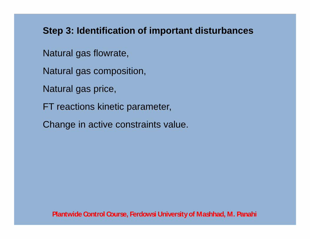
Step 3: Identification of important disturbances
Natural gas flowrate,
Natural gas composition,
Natural gas price,
FT reactions kinetic parameter,
Change in active constraints value.
Plantwide Control Course, Ferdowsi University of Mashhad, M. Panahi
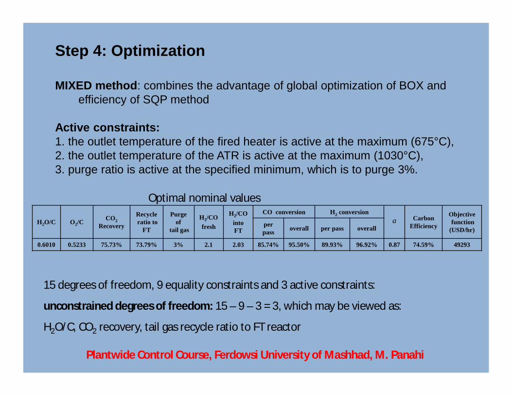
Step 4: Optimization
MIXED method: combines the advantage of global optimization of BOX and efficiency of SQP method
Active constraints:1. the outlet temperature of the fired heater is active at the maximum (675°C),2. the outlet temperature of the ATR is active at the maximum (1030°C),3. purge ratio is active at the specified minimum, which is to purge 3%.
H2O/C O2/CCO2
Recovery
Recycleratio to
FT
Purge of
tail gas
H2/COfresh
H2/COinto FT
CO conversion H2 conversionCarbon
Efficiency
Objectivefunction
(USD/hr)per pass overall per pass overall
0.6010 0.5233 75.73% 73.79% 3% 2.1 2.03 85.74% 95.50% 89.93% 96.92% 0.87 74.59% 49293
a
Optimal nominal values
15 degrees of freedom, 9 equality constraints and 3 active constraints:
unconstrained degrees of freedom: 15 – 9 – 3 = 3, which may be viewed as:
H2O/C, CO2 recovery, tail gas recycle ratio to FT reactor
Plantwide Control Course, Ferdowsi University of Mashhad, M. Panahi
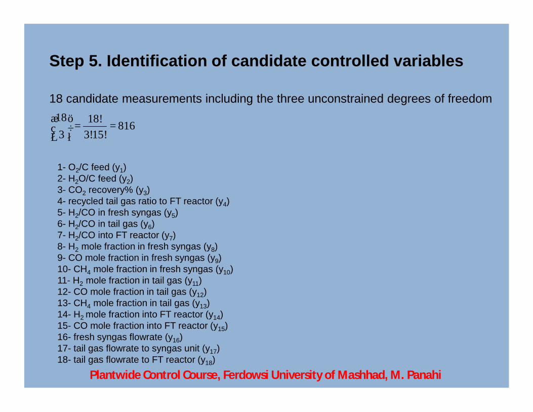
Step 5. Identification of candidate controlled variables
18 candidate measurements including the three unconstrained degrees of freedom18 18! 8163 3!15!
æ ö= =ç ÷
è ø
1- O2/C feed (y1)2- H2O/C feed (y2)3- CO2 recovery% (y3)4- recycled tail gas ratio to FT reactor (y4)5- H2/CO in fresh syngas (y5)6- H2/CO in tail gas (y6)7- H2/CO into FT reactor (y7)8- H2 mole fraction in fresh syngas (y8)9- CO mole fraction in fresh syngas (y9)10- CH4 mole fraction in fresh syngas (y10)11- H2 mole fraction in tail gas (y11)12- CO mole fraction in tail gas (y12)13- CH4 mole fraction in tail gas (y13)14- H2 mole fraction into FT reactor (y14)15- CO mole fraction into FT reactor (y15)16- fresh syngas flowrate (y16)17- tail gas flowrate to syngas unit (y17)18- tail gas flowrate to FT reactor (y18)
Plantwide Control Course, Ferdowsi University of Mashhad, M. Panahi
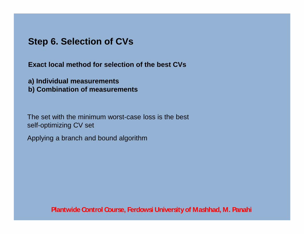
Step 6. Selection of CVs
Exact local method for selection of the best CVs
a) Individual measurementsb) Combination of measurements
The set with the minimum worst-case loss is the bestself-optimizing CV set
Applying a branch and bound algorithm
Plantwide Control Course, Ferdowsi University of Mashhad, M. Panahi
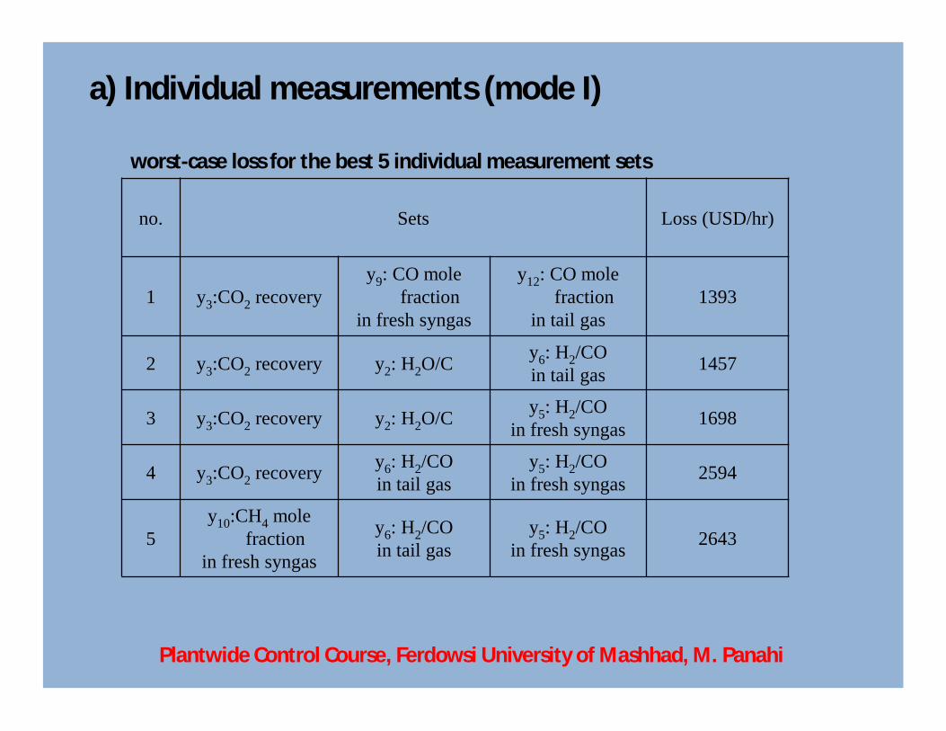
no. Sets Loss (USD/hr)
1 y3:CO2 recoveryy9: CO mole
fractionin fresh syngas
y12: CO mole fraction
in tail gas1393
2 y3:CO2 recovery y2: H2O/C y6: H2/COin tail gas 1457
3 y3:CO2 recovery y2: H2O/C y5: H2/COin fresh syngas 1698
4 y3:CO2 recovery y6: H2/COin tail gas
y5: H2/COin fresh syngas 2594
5y10:CH4 mole
fractionin fresh syngas
y6: H2/COin tail gas
y5: H2/COin fresh syngas 2643
a) Individual measurements (mode I)
worst-case loss for the best 5 individual measurement sets
Plantwide Control Course, Ferdowsi University of Mashhad, M. Panahi
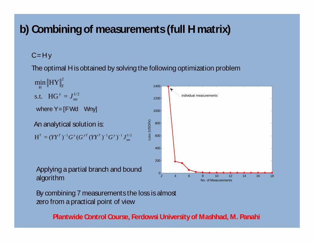
b) Combining of measurements (full H matrix)
C = H y
The optimal H is obtained by solving the following optimization problem2
FH1/ 2
min HY
s.t. HG yuuJ=
An analytical solution is:1 1 1 1/ 2H ( ) ( ( ) )T T y yT T y
uuYY G G YY G J- - -=
where Y = [F Wd Wny]
2 4 6 8 10 12 14 16 180
200
400
600
800
1000
1200
1400
No. of Measurements
Loss
(US
D/h
r)
individual measurements
By combining 7 measurements the loss is almost zero from a practical point of view
Applying a partial branch and bound algorithm
Plantwide Control Course, Ferdowsi University of Mashhad, M. Panahi
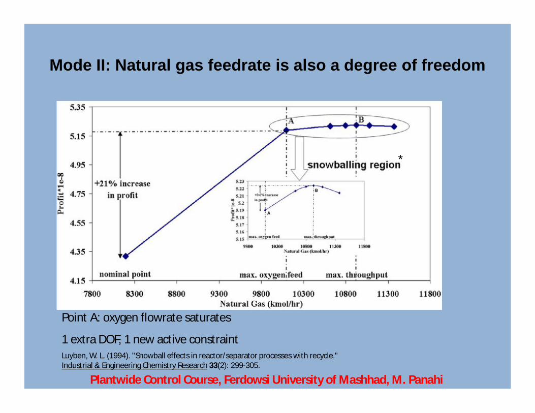
Mode II: Natural gas feedrate is also a degree of freedom
Point A: oxygen flowrate saturates
1 extra DOF, 1 new active constraintLuyben, W. L. (1994). "Snowball effects in reactor/separator processes with recycle." Industrial & Engineering Chemistry Research 33(2): 299-305.
*
Plantwide Control Course, Ferdowsi University of Mashhad, M. Panahi
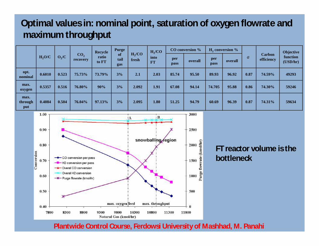
Optimal values in: nominal point, saturation of oxygen flowrate and maximum throughput
H2O/C O2/CCO2
recovery
Recycleratio
to FT
Purge oftail gas
H2/COfresh
H2/COinto FT
CO conversion % H2 conversion %Carbon
efficiency
Objective function(USD/hr)
per pass overall per
pass overall
opt. nominal 0.6010 0.523 75.73% 73.79% 3% 2.1 2.03 85.74 95.50 89.93 96.92 0.87 74.59% 49293
max. oxygen 0.5357 0.516 76.80% 90% 3% 2.092 1.91 67.08 94.14 74.705 95.88 0.86 74.30% 59246
max. through
put0.4084 0.504 76.04% 97.13% 3% 2.095 1.80 51.25 94.79 60.69 96.39 0.87 74.31% 59634
a
FT reactor volume is the bottleneck
Plantwide Control Course, Ferdowsi University of Mashhad, M. Panahi
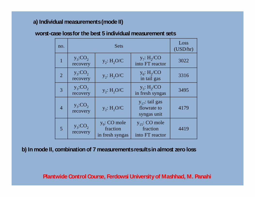
no. Sets Loss (USD/hr)
1 y3:CO2recovery y2: H2O/C y7: H2/CO
into FT reactor 3022
2 y3:CO2recovery y2: H2O/C y6: H2/CO
in tail gas 3316
3 y3:CO2recovery y2: H2O/C y5: H2/CO
in fresh syngas 3495
4 y3:CO2recovery y2: H2O/C
y17: tail gas flowrate to syngas unit
4179
5 y3:CO2recovery
y9: CO mole fraction
in fresh syngas
y15: CO mole fraction
into FT reactor4419
a) Individual measurements (mode II)
worst-case loss for the best 5 individual measurement sets
b) In mode II, combination of 7 measurements results in almost zero loss
Plantwide Control Course, Ferdowsi University of Mashhad, M. Panahi
The third individual measurements set is common in modes I&II the same setpoint for CO2 recovery and H2/CO ratio,
setpoint for H2O/C decreases from 0.6 to 0.4 (throughput manipulator)
Operation in snowballing region should be avoided (max. throughput in this case)
Saturation point of oxygen plant capacity is recommended for operation
Plantwide Control Course, Ferdowsi University of Mashhad, M. Panahi