Embed Size (px)
Citation preview
LECTURE 6
Chapter 8: The Cooling Load
1
Chapter 9: Energy Calculations –
DD Method
Chapter 8: The Cooling Load
• Heat gain is the rate at which energy is transferred to or generated within a space. It has two components:
(i) sensible heat, and
(ii) latent heat
• Heat gains usually occur in the following forms:
1. Solar radiation through openings.
2. Heat conduction through boundaries with convection and radiation from the inner surfaces into the space.
3. Sensible heat convection and radiation from internal objects.
4. Ventilation (outside air) and infiltration air.
5. Latent heat gains generated within the space.
2
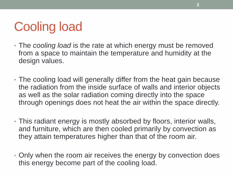
Cooling load
• The cooling load is the rate at which energy must be removed from a space to maintain the temperature and humidity at the design values.
• The cooling load will generally differ from the heat gain because the radiation from the inside surface of walls and interior objects as well as the solar radiation coming directly into the space through openings does not heat the air within the space directly.
• This radiant energy is mostly absorbed by floors, interior walls, and furniture, which are then cooled primarily by convection as they attain temperatures higher than that of the room air.
• Only when the room air receives the energy by convection does this energy become part of the cooling load.
3
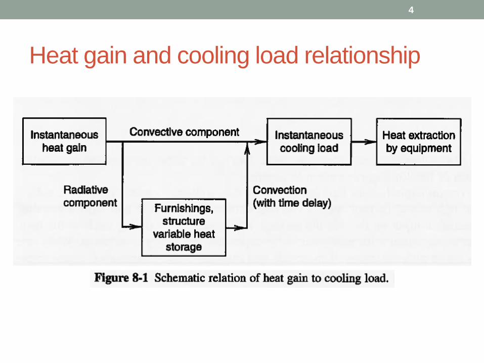
Heat gain and cooling load relationship
4
Thermal lag
• Heat storage and heat transfer characteristics of structure
and interior objects determine the thermal lag.
• This thermal lag determines the relationship between heat
gain and cooling load.
• The thermal mass (product of mass and specific heat cp)
of the structure and its contents must be considered.
• The reduction in peak cooling load because of the thermal
lag can be quite important in sizing the cooling equipment.
5
6
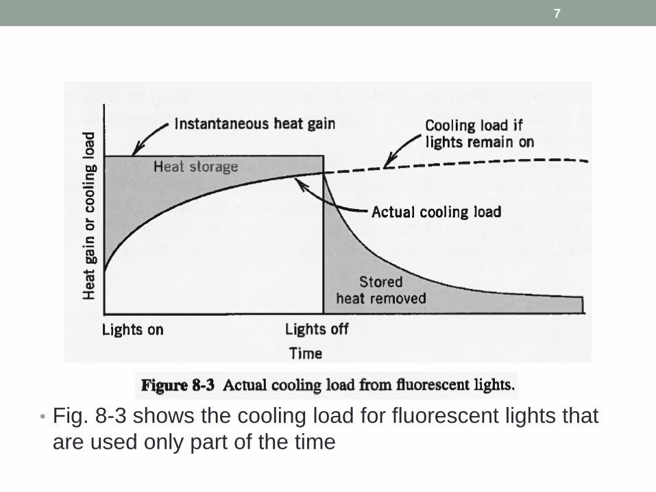
• Fig. 8-3 shows the cooling load for fluorescent lights that
are used only part of the time
7
• The part of the energy produced by lights, equipment, or people that is radiant energy is temporarily stored in the surroundings.
• Energy convected directly to the air by the lights and people, and later by the surroundings, goes into the cooling load.
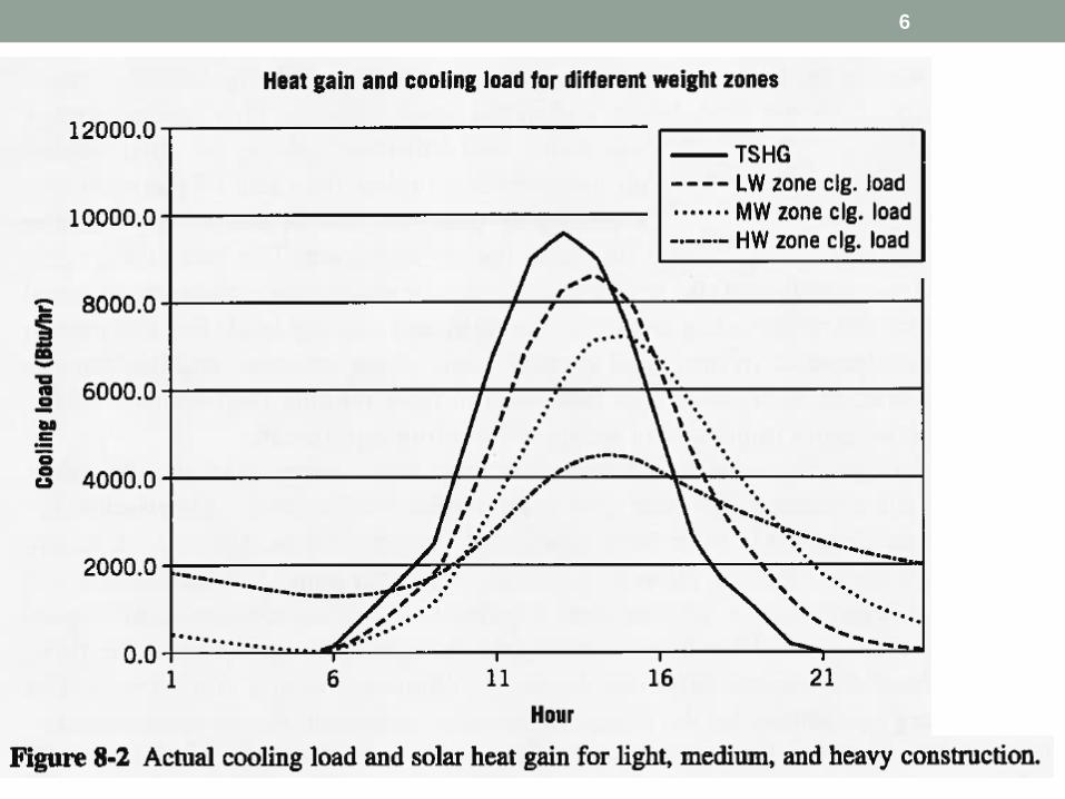
• The areas under the heat gain and actual cooling load curves of Fig. 8-3 are approximately equal.
• This means that about the same total amount of energy must be removed from the structure during the day; however, a larger portion is removed during the evening hours for heavier constructions.
8
Thermal lag
Heat extraction rate• Heat extraction rate is the rate at which energy is
removed from the space by the cooling and dehumidifying equipment.
• This rate is equal to the cooling load when the space conditions are constant and the equipment is operating.
• However, that is rarely the case because some fluctuation in room temperature is necessary for control system to operate.
• Because the cooling load is also below the peak or design value most of the time, intermittent or variable operation of cooling equipment is required.
9
Ex 8-1
• Describe a situation where the heat gain to the space is:
• (a) greater than the cooling load at a given time,
• (b) less than the cooling load at a given time, and
• (c) equal to the cooling load at a given time.
10
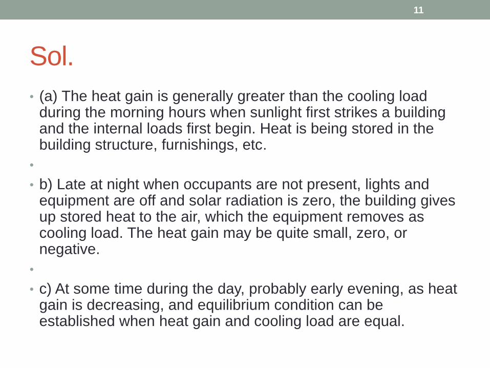
Sol.
• (a) The heat gain is generally greater than the cooling load during the morning hours when sunlight first strikes a building and the internal loads first begin. Heat is being stored in the building structure, furnishings, etc.
•
• b) Late at night when occupants are not present, lights and equipment are off and solar radiation is zero, the building gives up stored heat to the air, which the equipment removes as cooling load. The heat gain may be quite small, zero, or negative.
•
• c) At some time during the day, probably early evening, as heat gain is decreasing, and equilibrium condition can be established when heat gain and cooling load are equal.
11
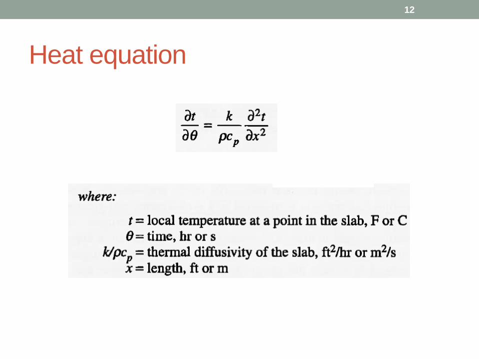
Heat equation
12
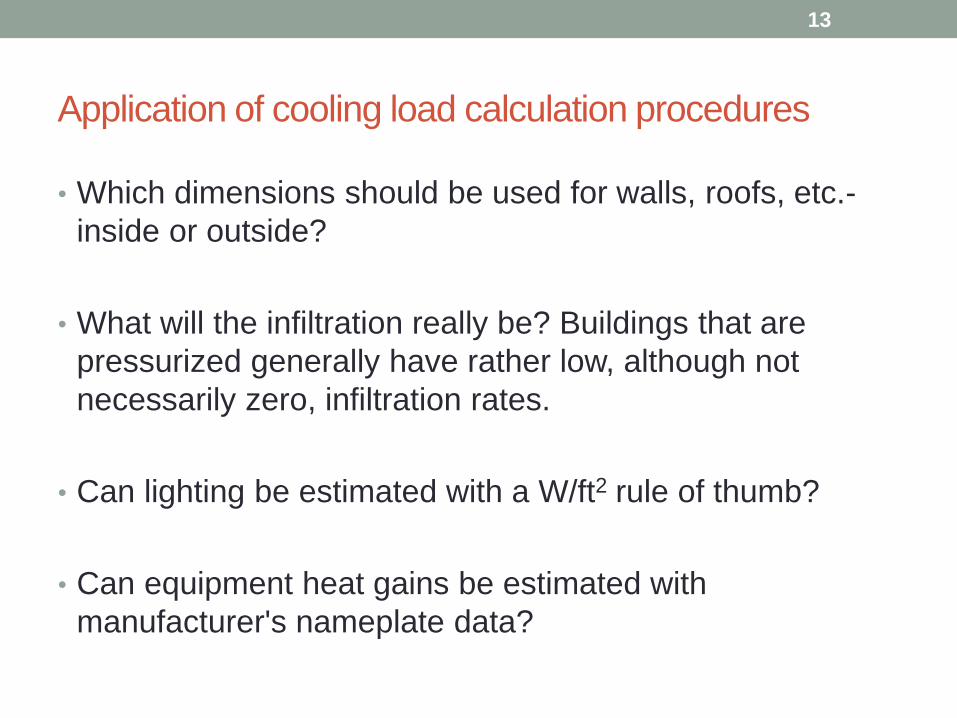
Application of cooling load calculation procedures
• Which dimensions should be used for walls, roofs, etc.-
inside or outside?
• What will the infiltration really be? Buildings that are
pressurized generally have rather low, although not
necessarily zero, infiltration rates.
• Can lighting be estimated with a W/ft2 rule of thumb?
• Can equipment heat gains be estimated with
manufacturer's nameplate data?
13
Design conditions
• Selecting outdoor design conditions for cooling presents a
problem similar to that for heating.
• It is not reasonable to design for the worst conditions on
record because a great excess of capacity will result.
• Heat storage capacity of the structure also plays an
important role in this regard.
• Massive structure will reduce effect of overload from short
intervals of outdoor temperature above design value.
14
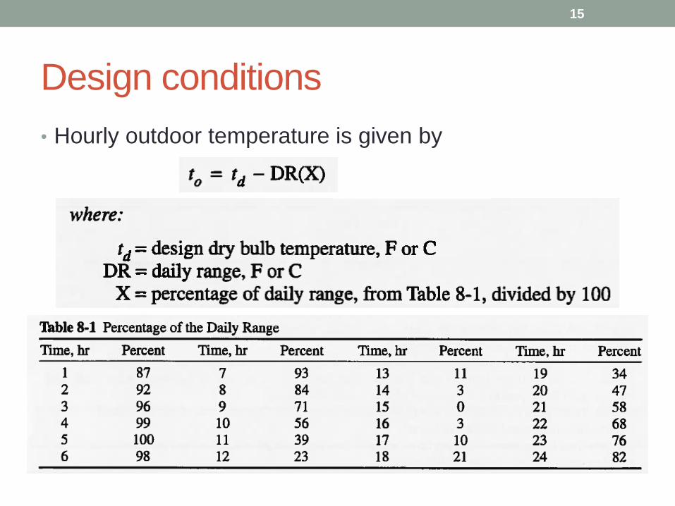
Design conditions
• Hourly outdoor temperature is given by
15
Internal heat gains
• People, lights, and equipment are often a significant
component of the cooling load in commercial and
institutional buildings.
• In fact, for many large office buildings, the internal heat
gains are the dominant source of cooling load; so much
so that many large office buildings require cooling year-
round, even in the middle of winter.
• Accordingly, internal heat gains form an important part of
cooling load calculations.
16
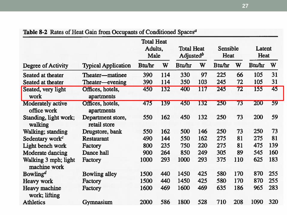
Internal heat gains - People• The heat gain from people has two components: sensible and
latent.
• The latent heat gain is assumed to become cooling load instantly, whereas the sensible heat gain is partially delayed depending on the nature of the conditioned space.
• The sensible heat gain for people generally is assumed to be 30% convective (instant cooling load) and 70% radiative (the delayed portion).
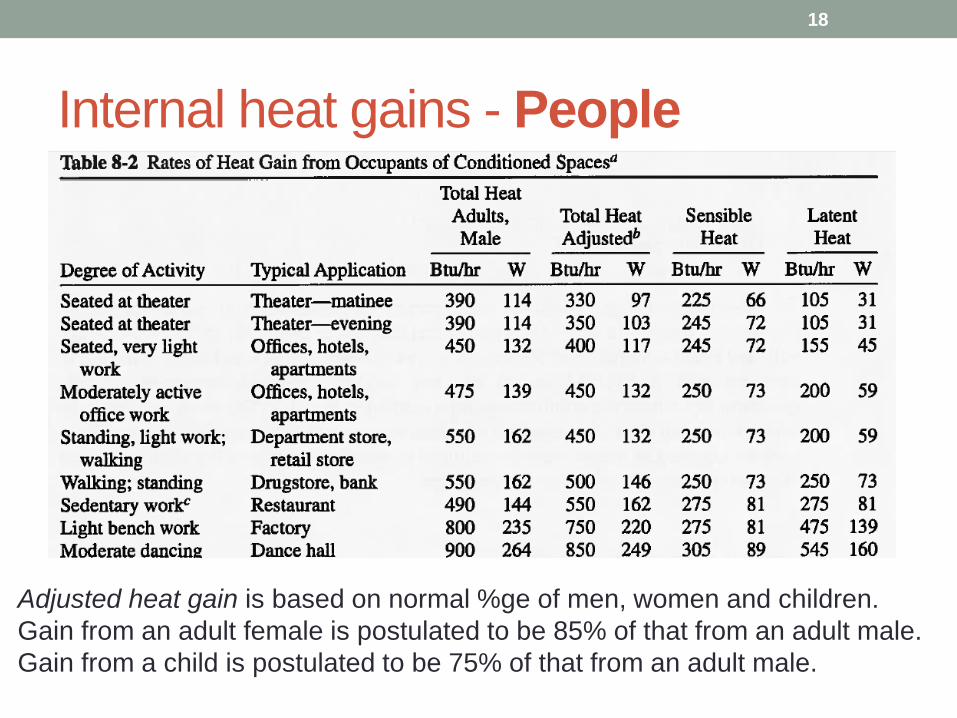
• Table 8-2 gives heat gain data from occupants in conditioned spaces.
• Last three columns are adjusted according to the normally expected percentages of men, women, and children for listed application.
17
Internal heat gains - People
18
Adjusted heat gain is based on normal %ge of men, women and children.
Gain from an adult female is postulated to be 85% of that from an adult male.
Gain from a child is postulated to be 75% of that from an adult male.
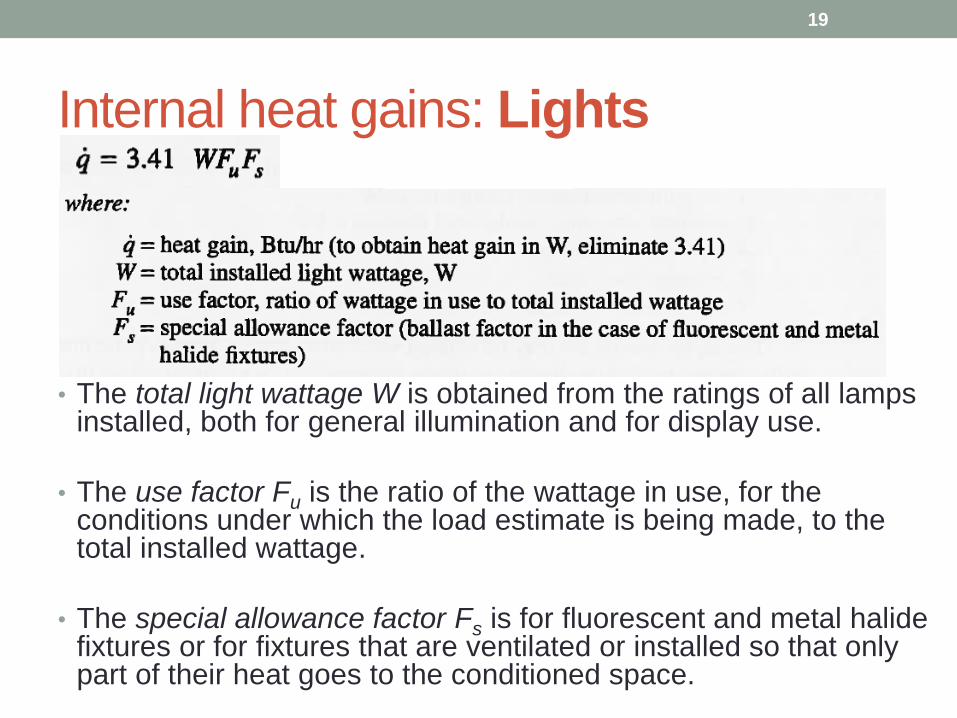
Internal heat gains: Lights
• The total light wattage W is obtained from the ratings of all lamps installed, both for general illumination and for display use.
• The use factor Fu is the ratio of the wattage in use, for the conditions under which the load estimate is being made, to the total installed wattage.
• The special allowance factor Fs is for fluorescent and metal halide fixtures or for fixtures that are ventilated or installed so that only part of their heat goes to the conditioned space.
19
Light fixtures
• A recessed light fixture will tend to transfer heat to the surrounding structure, whereas a hanging fixture tends to convect more heat directly to the space air.
• Some light fixtures are designed so that space air returns through them, carrying away heat that would otherwise go into the space.
• For ordinary design load estimation, the heat gain for each component may simply be calculated as a fraction of the total lighting load, by using judgment to estimate heat-to-space and heat-to-return percentage.
• Heat from fixtures ranges from 40% to 60% heat-to-return for ventilated fixtures down to 15% to 25% for unventilated fixtures.
• Heat gain to the space from fluorescent fixtures is often assumed to be 59% radiative and 41% convective.
• Heat gain from incandescent fixtures is typically assumed to be 80% radiative and 20% convective.
20
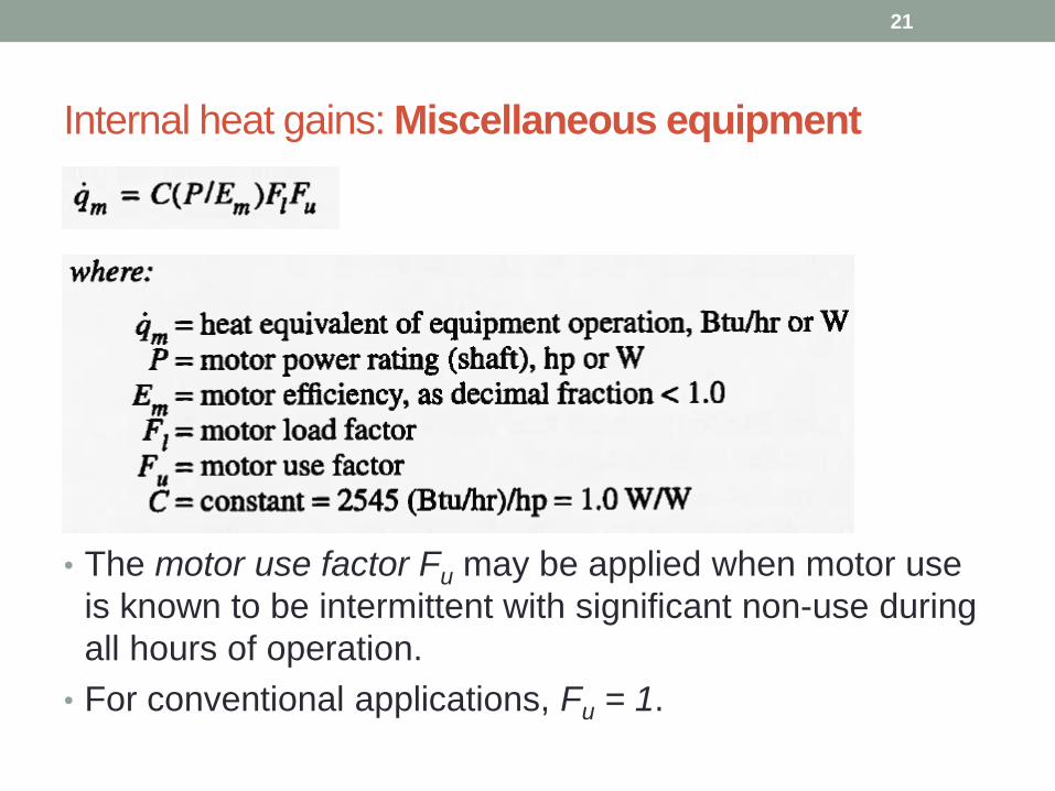
Internal heat gains: Miscellaneous equipment
• The motor use factor Fu may be applied when motor use
is known to be intermittent with significant non-use during
all hours of operation.
• For conventional applications, Fu = 1.
21
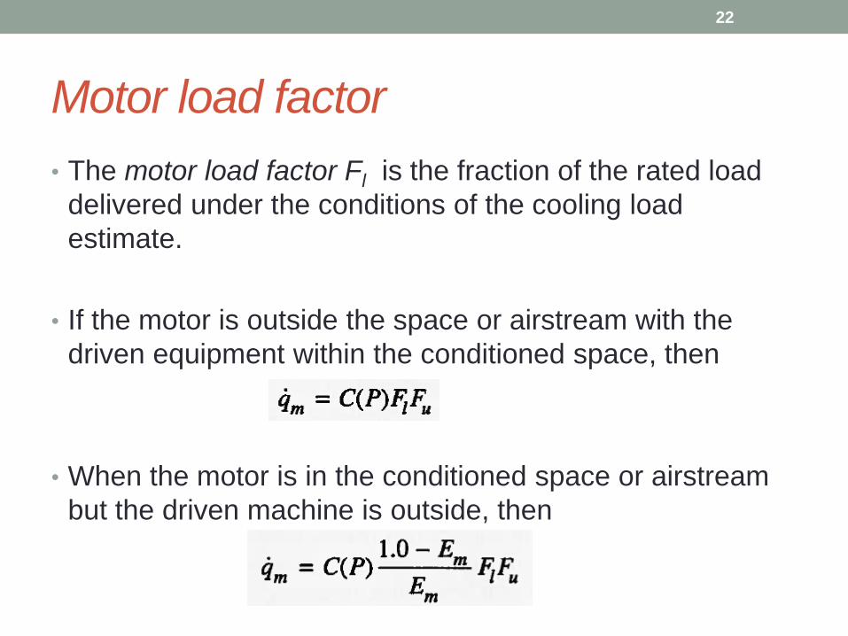
Motor load factor
• The motor load factor Fl is the fraction of the rated load
delivered under the conditions of the cooling load
estimate.
• If the motor is outside the space or airstream with the
driven equipment within the conditioned space, then
• When the motor is in the conditioned space or airstream
but the driven machine is outside, then
22
Equipment heat gain components
• Equipment heat gain is commonly assumed to be about
70% radiative and 30% convective for cooling load
calculations.
• Radiative fraction of fan-cooled electronic equipment is
considerably lower than 70%.
• Because of the diversity of appliance use and the effect of
thermostatic controls, the maximum hourly heat gain can
be estimated as 50% of the total nameplate or catalog
input ratings.
23
Hooded appliances
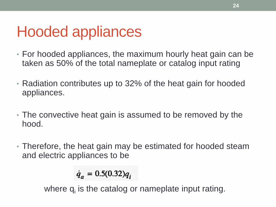
• For hooded appliances, the maximum hourly heat gain can be taken as 50% of the total nameplate or catalog input rating
• Radiation contributes up to 32% of the heat gain for hooded appliances.
• The convective heat gain is assumed to be removed by the hood.
• Therefore, the heat gain may be estimated for hooded steam and electric appliances to be
where qi is the catalog or nameplate input rating.
24
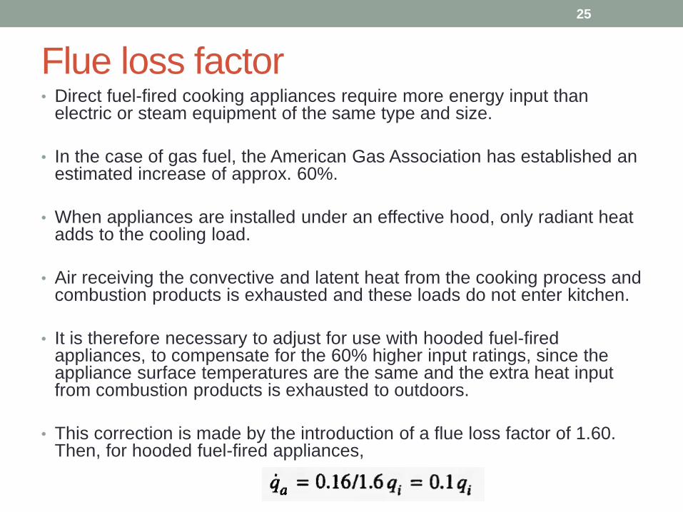
Flue loss factor• Direct fuel-fired cooking appliances require more energy input than
electric or steam equipment of the same type and size.
• In the case of gas fuel, the American Gas Association has established an estimated increase of approx. 60%.
• When appliances are installed under an effective hood, only radiant heat adds to the cooling load.
• Air receiving the convective and latent heat from the cooking process and combustion products is exhausted and these loads do not enter kitchen.
• It is therefore necessary to adjust for use with hooded fuel-fired appliances, to compensate for the 60% higher input ratings, since the appliance surface temperatures are the same and the extra heat input from combustion products is exhausted to outdoors.
• This correction is made by the introduction of a flue loss factor of 1.60. Then, for hooded fuel-fired appliances,
25
Ex 8-15
• A large office space has an average occupancy of 30
people from 8:00A.M. to 5:00P.M. Lighting is 1.5 W/ft2 of
recessed, unvented fluorescent fixtures on from 8:00A.M.
to 6:00P.M. Computers, photocopiers, fax machines, etc.
create a heat gain of 1 W/ft 2.
• (a) Compute the sensible and latent heat gain at 4:00P.M.
for the space, assuming a floor area of 4000 ft2.
• (b) For the sensible heat gain, estimate the radiative and
convective portions.
26
27
Heat Balance Method
• The heat balance method ensures that all energy flows in each zone are balanced.
• It involves the solution of a set of energy balance equations for the zone air and the interior and exterior surfaces of each wall, roof, and floor.
• These energy balance equations are combined with equations for transient conduction heat transfer through walls and roofs.
• These are also combined with algorithms or data for weather conditions including outdoor air tdb, twb, Gt, etc.
28
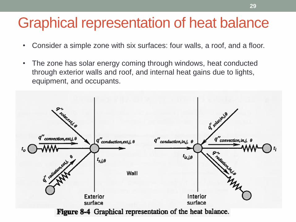
Graphical representation of heat balance
29
• Consider a simple zone with six surfaces: four walls, a roof, and a floor.
• The zone has solar energy coming through windows, heat conducted
through exterior walls and roof, and internal heat gains due to lights,
equipment, and occupants.
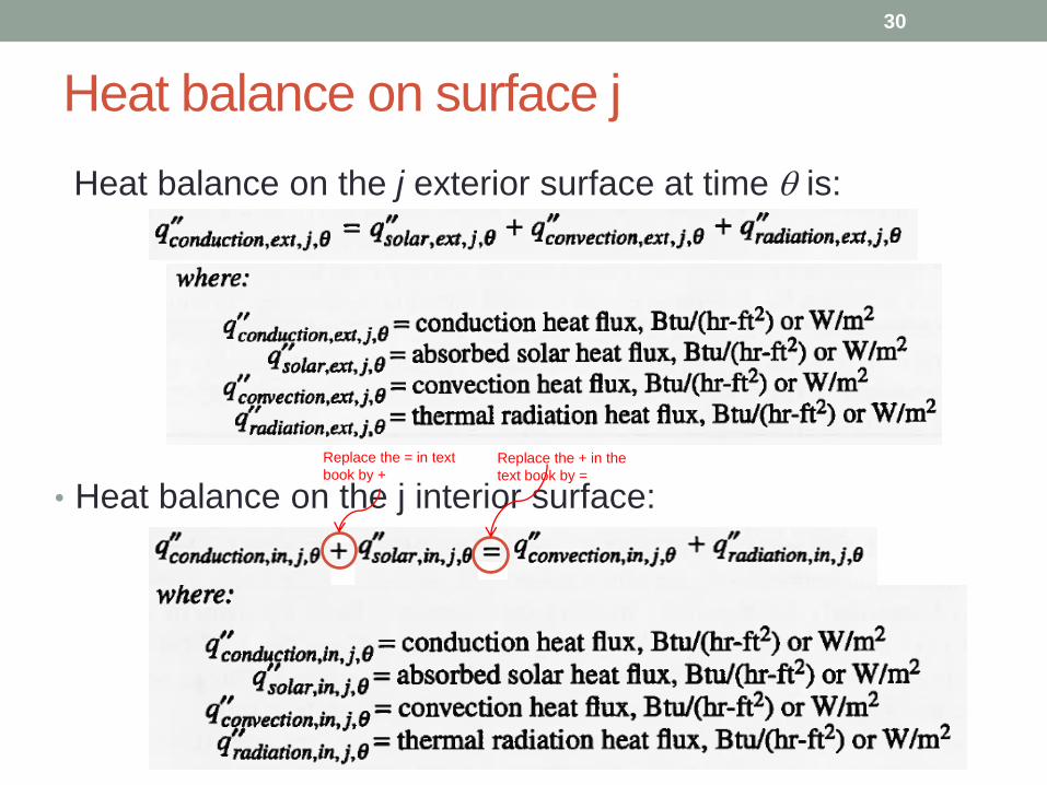
Heat balance on surface j
Heat balance on the j exterior surface at time q is:
30
• Heat balance on the j interior surface:
Replace the = in text
book by + Replace the + in the
text book by =
Limitations
• q”conduction,ext,j,q q”conduction,in,j,q , unless steady-state heat
transfer conditions prevail. This would be unusual for
cooling load calculations.
• Both the interior surface and exterior surfaces may radiate
to several surfaces or objects. For this figure, only one
interchange is shown.
31
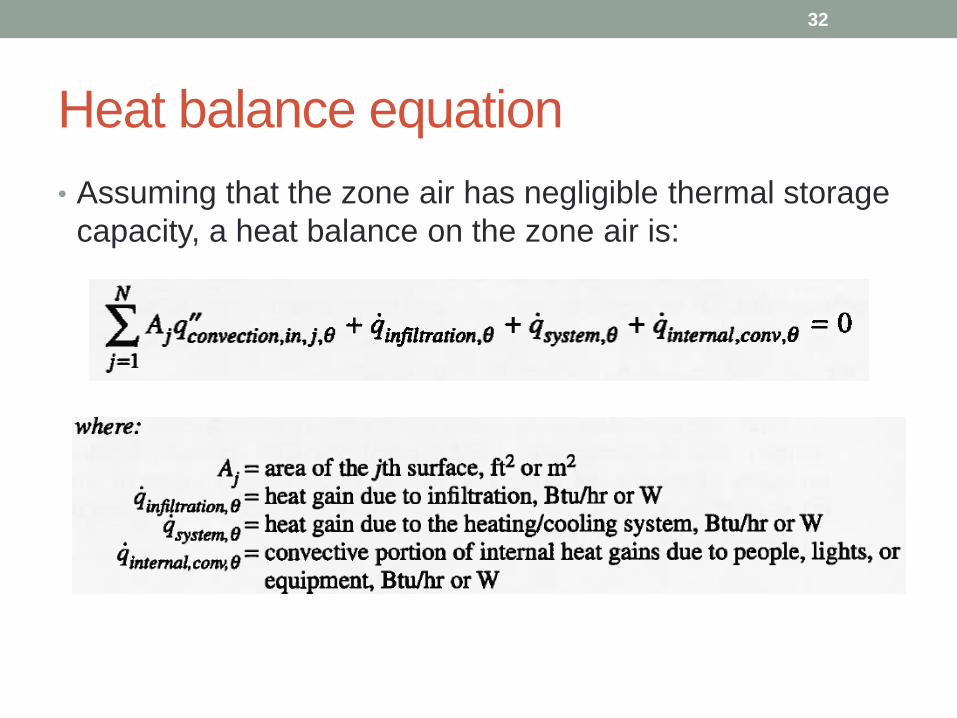
Heat balance equation
• Assuming that the zone air has negligible thermal storage
capacity, a heat balance on the zone air is:
32
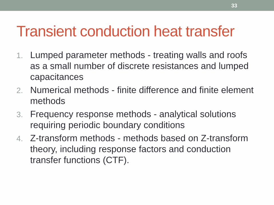
Transient conduction heat transfer
1. Lumped parameter methods - treating walls and roofs
as a small number of discrete resistances and lumped
capacitances
2. Numerical methods - finite difference and finite element
methods
3. Frequency response methods - analytical solutions
requiring periodic boundary conditions
4. Z-transform methods - methods based on Z-transform
theory, including response factors and conduction
transfer functions (CTF).
33
It should be noted that:
• The current values of interior and exterior surface temperature are not usually known and must be determined simultaneously with the surface heat balances.
• When a calculation is started, past values of the surface temperatures and heat fluxes are not known.
• Therefore, it is necessary to assume past values for the initial calculation and then to iterate on the first day of the calculation until a steady periodic solution is reached.
• Conduction transfer functions (CTF) coefficients may be obtained with the load calculation program on the website.
34
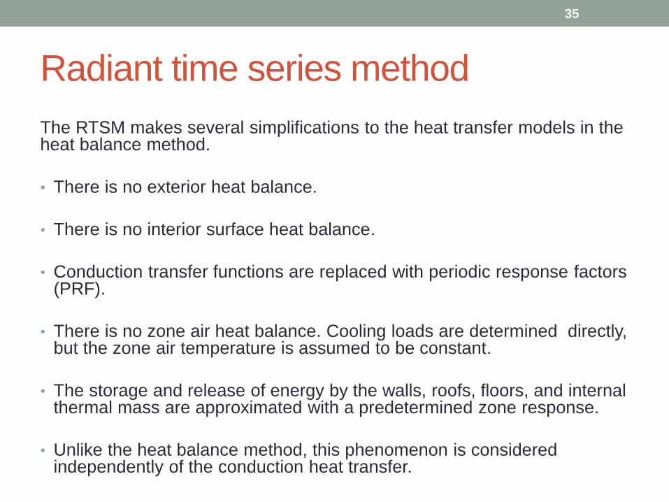
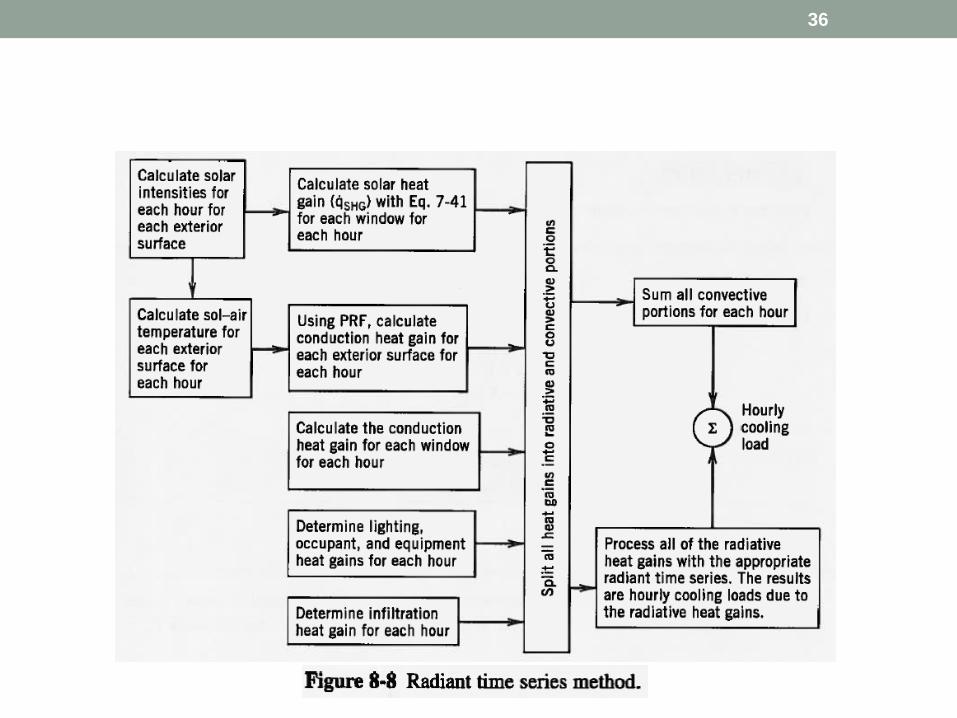
Radiant time series method
The RTSM makes several simplifications to the heat transfer models in the heat balance method.
• There is no exterior heat balance.
• There is no interior surface heat balance.
• Conduction transfer functions are replaced with periodic response factors (PRF).
• There is no zone air heat balance. Cooling loads are determined directly, but the zone air temperature is assumed to be constant.
• The storage and release of energy by the walls, roofs, floors, and internal thermal mass are approximated with a predetermined zone response.
• Unlike the heat balance method, this phenomenon is considered independently of the conduction heat transfer.
35
36
• It is often desirable to estimate the quantity of energy
necessary to heat and cool the structure under typical
weather conditions and with typical inputs from internal
heat sources.
• This procedure has a different emphasis than design load
calculations, which are usually made to determine size or
capacity for one set of design conditions.
• For energy calculations, we are more interested in what
might happen over a typical year, with constantly
changing sky conditions and varying internal heat gains.
37
Chapter 9:
Energy Calculations and Building Simulation
• Energy calculations involve simulation of the building and
HVAC system - predicting over time, with hourly or shorter
time steps, the temperatures, energy flows, and energy
consumption in the building and system.
• Furthermore, building simulation may be extended to
analyze other related aspects of the building performance
- such as controls, thermal comfort, air flow, lighting,
daylighting, and visual comfort.
38
Energy calculations
Degree-Day Procedure
• This was the first method developed to estimate energy
requirements and was intended to estimate heating
energy for single-family residential houses.
• The original degree-day procedure was based on the
assumption that on a long term basis, solar and internal
gains for a residential structure will offset heat loss when
the mean daily outdoor temperature is 65 F (18 C).
• It was further assumed that fuel consumption will be
proportional to the difference between the mean daily
temperature and 65 F or 18 C.
39
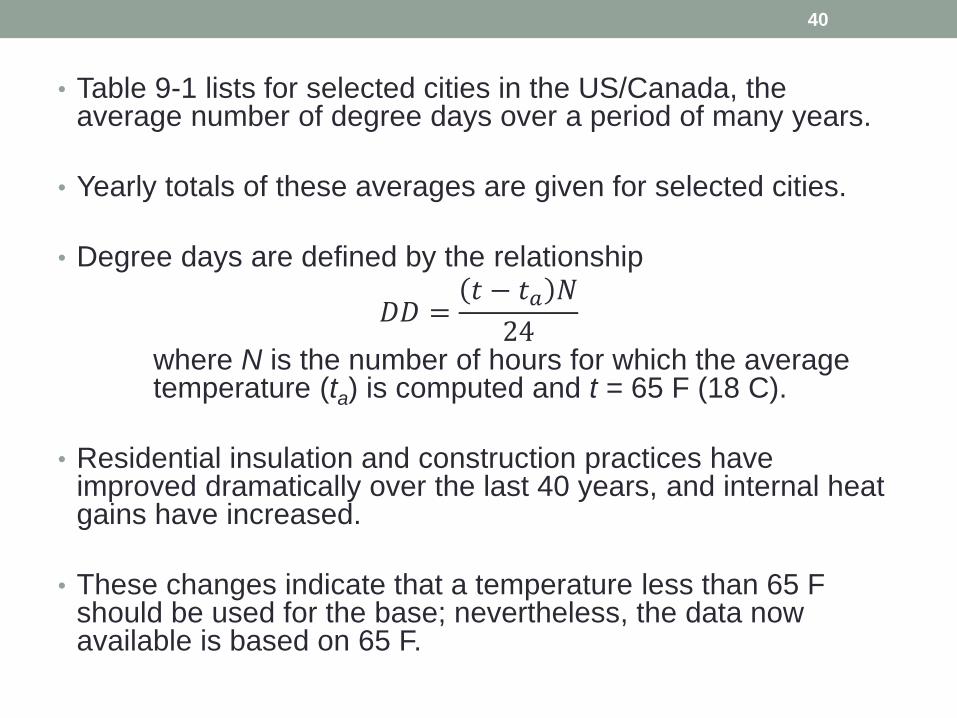
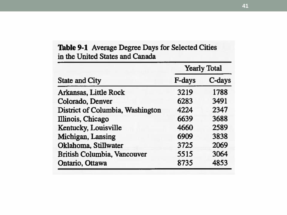
• Table 9-1 lists for selected cities in the US/Canada, the average number of degree days over a period of many years.
• Yearly totals of these averages are given for selected cities.
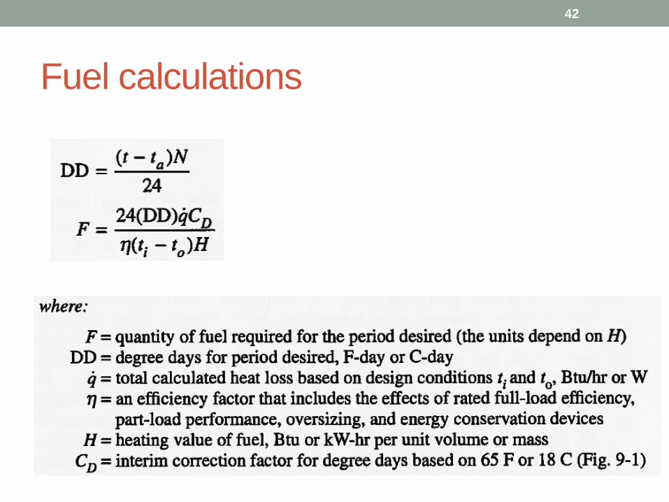
• Degree days are defined by the relationship
𝐷𝐷 =𝑡 − 𝑡𝑎 𝑁
24where N is the number of hours for which the average temperature (ta) is computed and t = 65 F (18 C).
• Residential insulation and construction practices have improved dramatically over the last 40 years, and internal heat gains have increased.
• These changes indicate that a temperature less than 65 F should be used for the base; nevertheless, the data now available is based on 65 F.
40
41
42
Fuel calculations
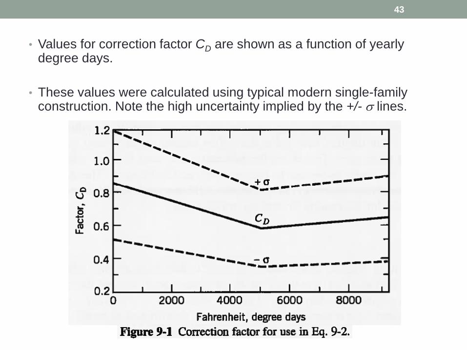
• Values for correction factor CD are shown as a function of yearly degree days.
• These values were calculated using typical modern single-family construction. Note the high uncertainty implied by the +/- s lines.
43
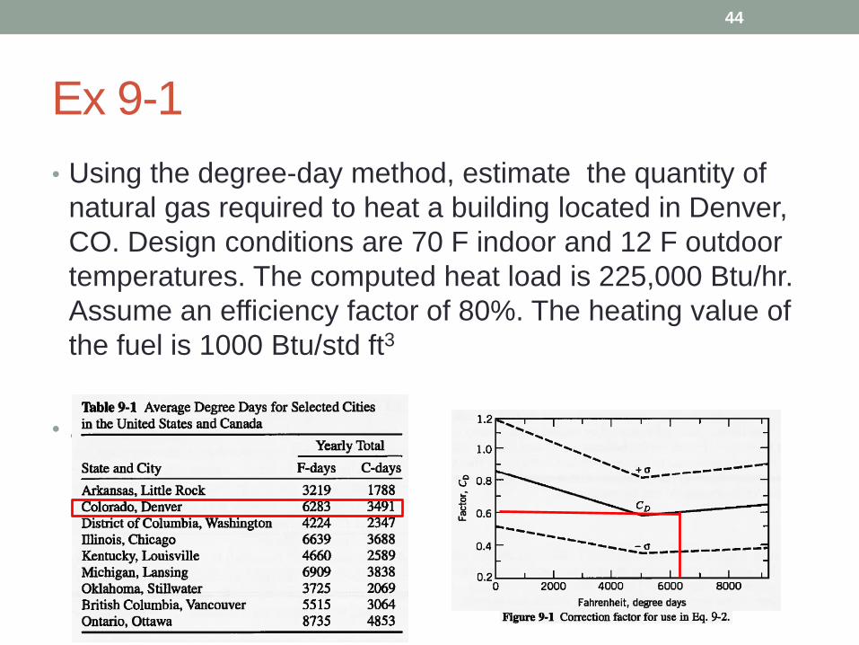
Ex 9-1
• Using the degree-day method, estimate the quantity of
natural gas required to heat a building located in Denver,
CO. Design conditions are 70 F indoor and 12 F outdoor
temperatures. The computed heat load is 225,000 Btu/hr.
Assume an efficiency factor of 80%. The heating value of
the fuel is 1000 Btu/std ft3
• .
44
Ex 9-2
• If electric resistance heat were used to heat the building
mentioned in Problem 9-1, how much energy would be
required in kW-hr, assuming a 100% efficiency factor? If
the electrical energy costs 10¢/kWh and natural gas costs
$4.5/mcf, what are the relative heating costs? Assuming
a power plant efficiency of 33%, compare the total
amounts of energy in terms of mcf of gas required to heat
the building using a gas furnace and an electric furnace.
45
Limitations of degree day method
• A serious shortcoming of the degree-day method is its
inability to model equipment whose performance depends
on outdoor ambient conditions.
• A heat pump is an example.
• Degree days are useful in comparing the heating
requirements from one location to another.
• Sometimes degree days are used as a parameter in
studying energy data such as utility costs.
46
Variable-Base Degree-Day Method
• The variable-base degree-day procedure is a generalization of the degree-day method.
• The concept is unchanged, but counts degree days based on the balance point, defined as the temperature where the building requires neither heating nor cooling.
• This method recognizes that internal heat gains that offset heating requirements may vary from one building to another.
• Therefore, the procedure accounts for only the energy required to offset the heat losses due to transmission and infiltration.
• This method is not recommended for heat pump or cooling applications.
47
Other aspects of building simulation
• Existing buildings
• Natural ventilation and air flow
• Lighting, daylighting, and visualization
• Thermal comfort
• Moisture transport and mold growth
• Controls
• Fire
• Building-integrated renewable energy
48