Embed Size (px)
DESCRIPTION
gjh
Citation preview
Laws on Temperature and Temperature Scales
“The temperature of a substance is the degree of hotness or coldness of the substance. A hot substance is said to have a high temperature whereas a cold substance is said to have a low temperature.”
# Therefore,
i)the temperature of a substance is an indication of the average kinetic energy of the molecules of the substance.
ii) Heat always flow from a body at higher temperature to the body at lower temperature.
iii) When two objects of the same material are placed together, the objectwith higher temperature cools while the cooler object gets warmer until a point is reached after which no more changes occurs.
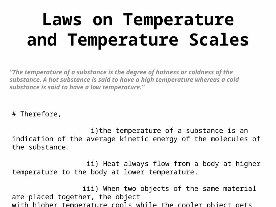
It can easily be demonstrated by following two laws:
• THERMAL EQUILIBRIUM :-says that, “Temperature is that quantity which is same for both the system when they are in thermal equilibrium.”
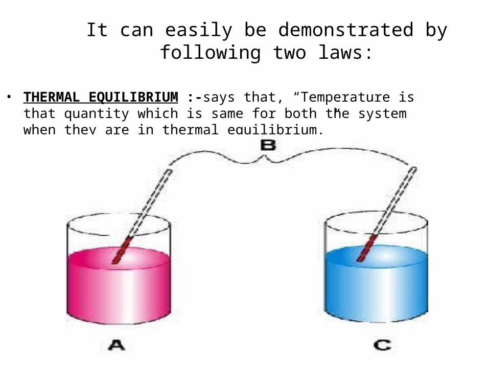
ZEROTH LAW OF THERMODYNAMICS:-state that "If two systems are separately in thermal equilibrium with a third,then they must also be in thermal equilibrium with each other, and they all have the same temperature regardless of the kind of the system they are."
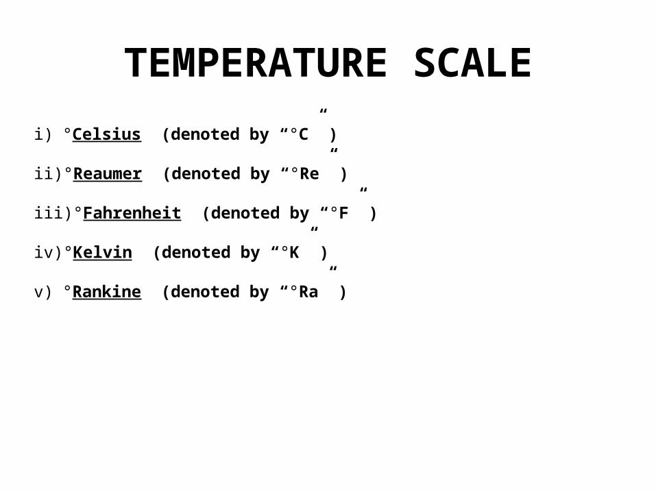
TEMPERATURE SCALEi) °Celsius (denoted by “°C” )
ii) °Reaumer (denoted by “°Re” )
iii) °Fahrenheit (denoted by “°F” )
iv) °Kelvin (denoted by “°K” )
v) °Rankine (denoted by “°Ra” )
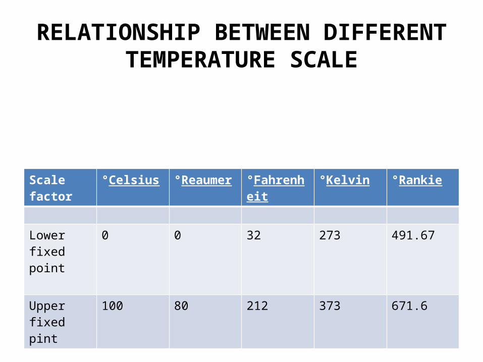
RELATIONSHIP BETWEEN DIFFERENT TEMPERATURE SCALE
Scale factor °Celsius °Reaumer °Fahrenheit °Kelvin °Rankie
Lower fixed point
0 0 32 273 491.67
Upper fixed pint
100 80 212 373 671.6
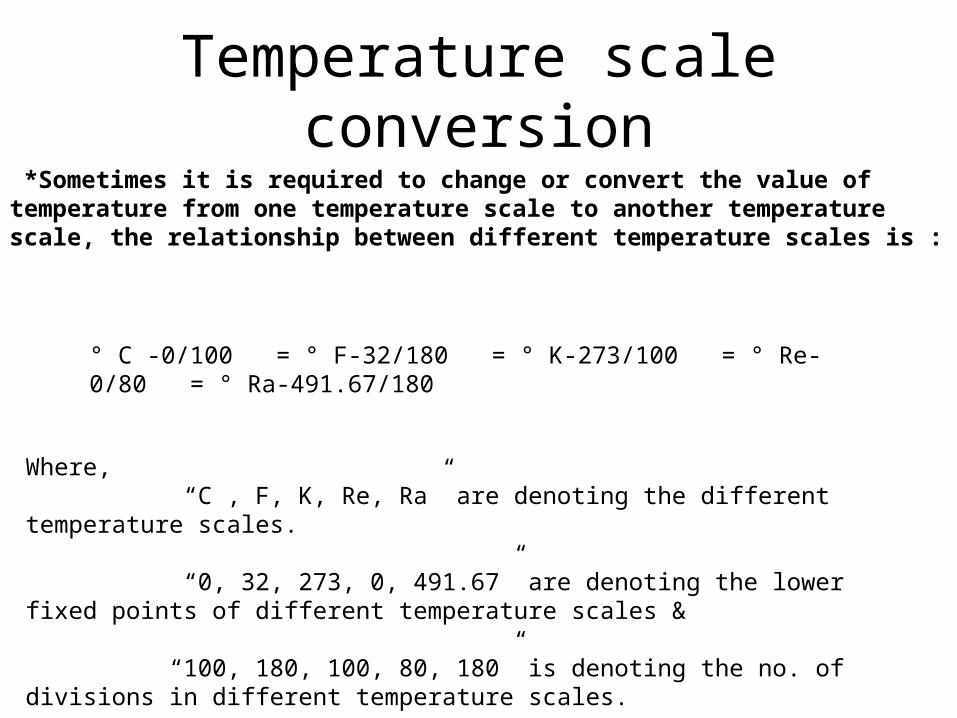
Temperature scale conversion *Sometimes it is required to change or convert the value of temperature from one temperature scale to another temperature scale, the relationship between different temperature scales is :
° C -0/100 = ° F-32/180 = ° K-273/100 = ° Re-0/80 = ° Ra-491.67/180
Where, “C , F, K, Re, Ra” are denoting the different temperature scales.
“0, 32, 273, 0, 491.67” are denoting the lower fixed points of different temperature scales &
“100, 180, 100, 80, 180” is denoting the no. of divisions in different temperature scales.
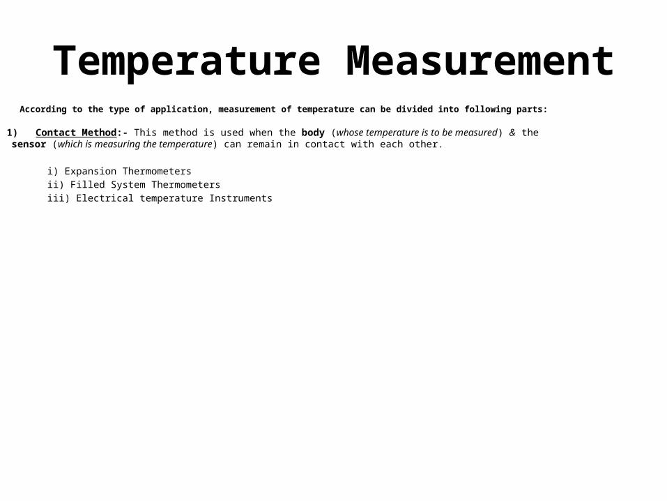
According to the type of application, measurement of temperature can be divided into following parts:
1) Contact Method:- This method is used when the body (whose temperature is to be measured) & the sensor (which is measuring the temperature) can remain in contact with each other.
i) Expansion Thermometers ii) Filled System Thermometers iii) Electrical temperature Instruments
Temperature Measurement
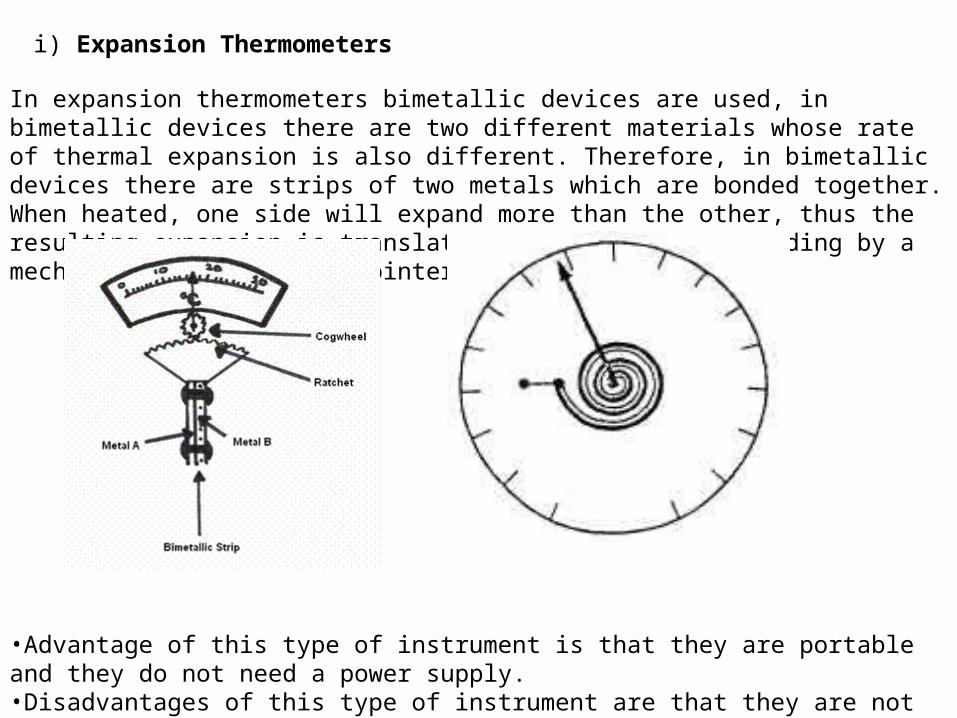
In expansion thermometers bimetallic devices are used, in bimetallic devices there are two different materials whose rate of thermal expansion is also different. Therefore, in bimetallic devices there are strips of two metals which are bonded together. When heated, one side will expand more than the other, thus the resulting expansion is translated into temperature reading by a mechanical linkage to a pointer.
•Advantage of this type of instrument is that they are portable and they do not need a power supply.•Disadvantages of this type of instrument are that they are not as accurate as other devices and they do not readily lend themselves to temperature recording.
i) Expansion Thermometers
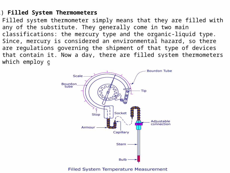
ii) Filled System ThermometersFilled system thermometer simply means that they are filled with any of the substitute. They generally come in two main classifications: the mercury type and the organic-liquid type. Since, mercury is considered an environmental hazard, so there are regulations governing the shipment of that type of devices that contain it. Now a day, there are filled system thermometers which employ gas instead of liquids.
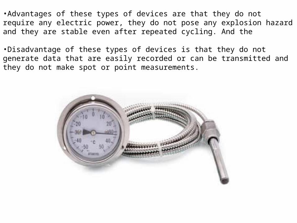
•Advantages of these types of devices are that they do not require any electric power, they do not pose any explosion hazard and they are stable even after repeated cycling. And the
•Disadvantage of these types of devices is that they do not generate data that are easily recorded or can be transmitted and they do not make spot or point measurements.
iii) Electrical temperature Instruments
These types of instruments sense the temperature in the terms of electrical quantities like voltage, resistance etc . Therefore, we can say that these types of instruments are not directing indicating thermometers like mercury in glass devices . In the majority of industrial and laboratory processes the measurement point is usually far from the indicating or controlling instrument. This may be due to necessity (e.g. an adverse environment) or convenience (e.g.centralized data acquisition). Therefore; Devices are required which convert temperature in to another form of signal, usually electrical quantities .
•The most common devices used in these types of temperature instruments are (a) thermocouples, (b) resistance thermometers and (c) Thermistors .
a) Thermocouples (T/C)
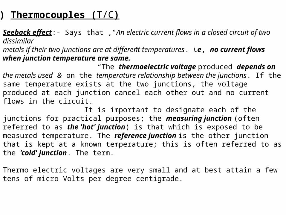
Seeback effect:- Says that ,“An electric current flows in a closed circuit of two dissimilarmetals if their two junctions are at different temperatures. i.e, no current flows when junction temperature are same.” “The thermoelectric voltage produced depends on the metals used & on the temperature relationship between the junctions. If the same temperature exists at the two junctions, the voltage produced at each junction cancel each other out and no current flows in the circuit. It is important to designate each of the junctions for practical purposes; the measuring junction (often referred to as the 'hot' junction) is that which is exposed to be measured temperature. The reference junction is the other junction that is kept at a known temperature; this is often referred to as the 'cold' junction. The term. Thermo electric voltages are very small and at best attain a few tens of micro Volts per degree centigrade.
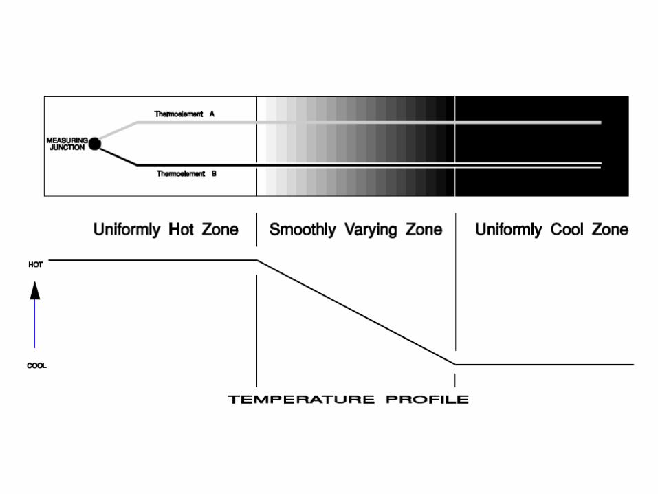
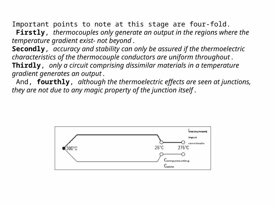
Important points to note at this stage are four-fold. Firstly, thermocouples only generate an output in the regions where the temperature gradient exist- not beyond. Secondly, accuracy and stability can only be assured if the thermoelectric characteristics of the thermocouple conductors are uniform throughout. Thirdly, only a circuit comprising dissimilar materials in a temperature gradient generates an output. And, fourthly, although the thermoelectric effects are seen at junctions, they are not due to any magic property of the junction itself.
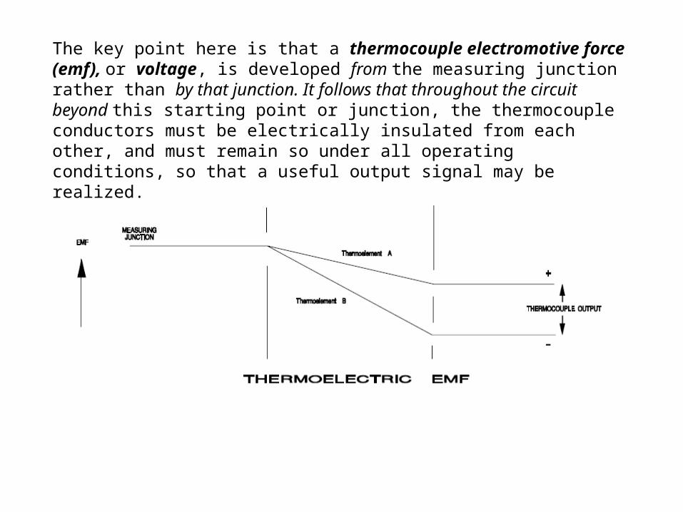
The key point here is that a thermocouple electromotive force (emf), or voltage, is developed from the measuring junction rather than by that junction. It follows that throughout the circuit beyond this starting point or junction, the thermocouple conductors must be electrically insulated from each other, and must remain so under all operating conditions, so that a useful output signal may be realized.
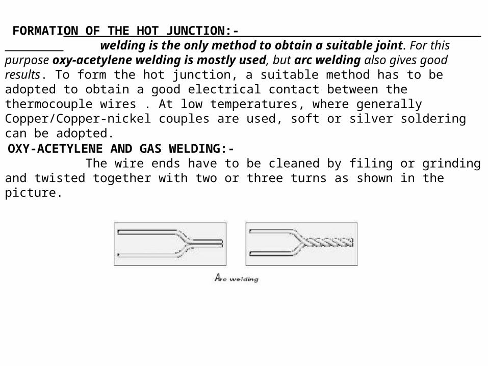
FORMATION OF THE HOT JUNCTION:- welding is the only method to obtain a suitable joint. For this purpose oxy-acetylene welding is mostly used, but arc welding also gives good results. To form the hot junction, a suitable method has to be adopted to obtain a good electrical contact between the thermocouple wires . At low temperatures, where generally Copper/Copper-nickel couples are used, soft or silver soldering can be adopted.
OXY-ACETYLENE AND GAS WELDING:- The wire ends have to be cleaned by filing or grinding and twisted together with two or three turns as shown in the picture.
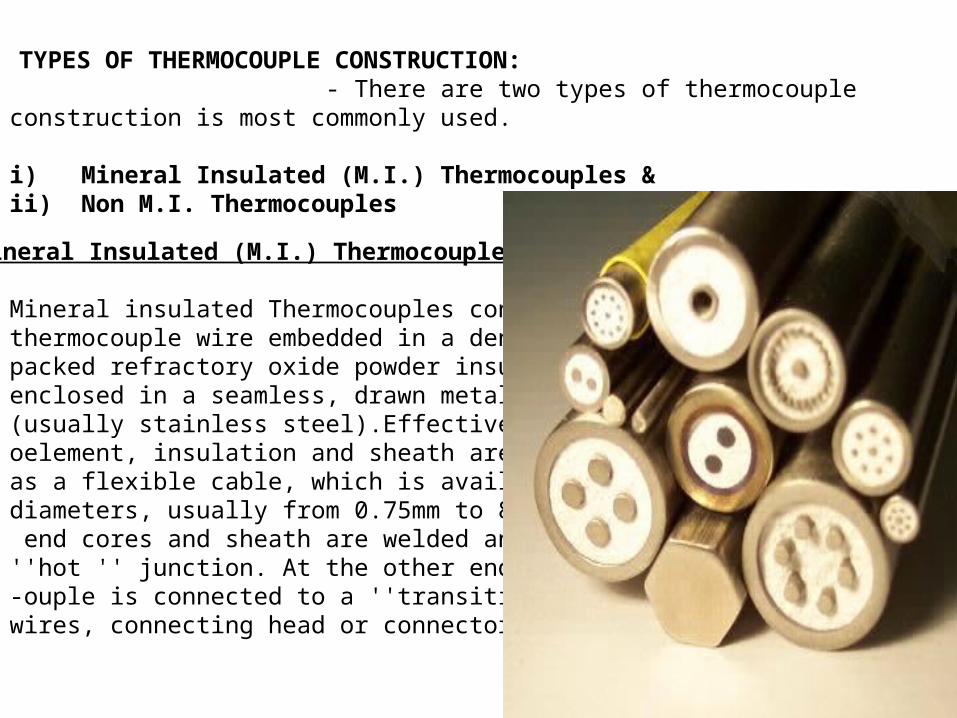
TYPES OF THERMOCOUPLE CONSTRUCTION: - There are two types of thermocouple construction is most commonly used.
i) Mineral Insulated (M.I.) Thermocouples &ii) Non M.I. Thermocouples
i) Mineral Insulated (M.I.) Thermocouples :- Mineral insulated Thermocouples consist of thermocouple wire embedded in a densely packed refractory oxide powder insulate all enclosed in a seamless, drawn metal sheath (usually stainless steel).Effectively the therm-oelement, insulation and sheath are combined as a flexible cable, which is available in different diameters, usually from 0.75mm to 8mm. At one end cores and sheath are welded and from a ''hot '' junction. At the other end, the thermoc-ouple is connected to a ''transition'' of extension wires, connecting head or connector.
Advantages of mineral insulated thermocouple are :-a) Small over all dimension and high flexibility, which enable temperature measurement in location with poor accessibility.b) Good mechanical strengthc) Protection of the thermo element wires against oxidation, corrosion and contamination.d) Fast thermal response
The mineral oxides used for insulation are highly hygroscopic and open-ended cables must be effectively sealed(usually with epoxy resins) to prevent moisture take-up. A carefully prepared mineral insulated thermocouple will normally have a high value of insulation resistance (many hundreds of mega ohms).
ii) NON M.I. THERMOCOUPLES :- In Non-M.I. thermocouples, thermocouple wires are either insulated with ceramic beads or after insulation of ceramic, covered by a metal sheath (usually stainless steel) and some form of termination (extension lead, connecting head or connector for example) is provided. In this type of 1 construction thermocouple wires are protected from the measuring environment when a sheath protection is provided. The sheath material is dependent on the measuring environment usually stainless steel is used. According to the corrosive environment sheath selection is changed. This construction does not provide flexibility& not found in small sizes. Not too good mechanical strength.In Non M.I. construction sheath may be of ceramic or metal as per suitability. Exposed, Grounded and Ungrounded all types of junctions are formed in both the M.I, & Non M.I. construction.
THERMOCOUPLE TYPES :-
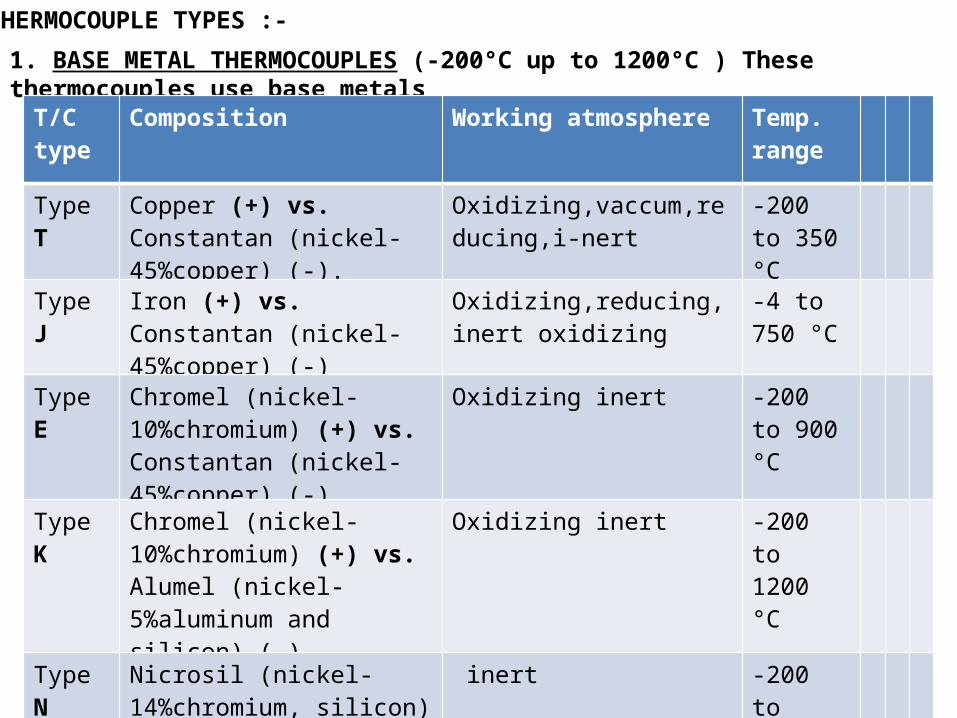
1. BASE METAL THERMOCOUPLES (-200°C up to 1200°C ) These thermocouples use base metals
T/C type
Composition Working atmosphere Temp. range
Type T Copper (+) vs. Constantan (nickel-45%copper) (-).
Oxidizing,vaccum,reducing,i-nert
-200 to 350 °C
Type J Iron (+) vs. Constantan (nickel-45%copper) (-)
Oxidizing,reducing,inert oxidizing
-4 to 750 °C
Type E Chromel (nickel-10%chromium) (+) vs. Constantan (nickel-45%copper) (-)
Oxidizing inert -200 to 900 °C
Type K Chromel (nickel-10%chromium) (+) vs. Alumel (nickel-5%aluminum and silicon) (-)
Oxidizing inert -200 to 1200 °C
Type N Nicrosil (nickel-14%chromium, silicon) (+) vs. Nisil (nickel-4%silicon, magnesium) (-)
inert -200 to 1200°C
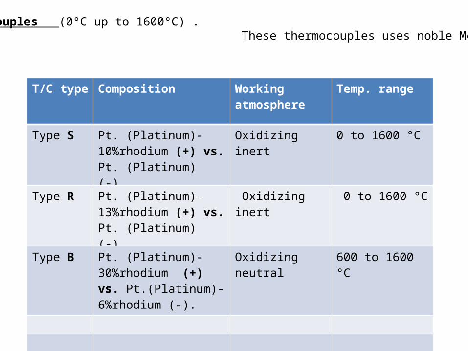
2) Noble Metal thermocouples (0°C up to 1600°C) . These thermocouples uses noble Metal (Platinum- Rhodium)
T/C type Composition Working atmosphere
Temp. range
Type S Pt. (Platinum)-10%rhodium (+) vs. Pt. (Platinum) (-).
Oxidizing inert 0 to 1600 °C
Type R Pt. (Platinum)-13%rhodium (+) vs. Pt. (Platinum) (-).
Oxidizing inert 0 to 1600 °C
Type B Pt. (Platinum)-30%rhodium (+) vs. Pt.(Platinum)-6%rhodium (-).
Oxidizing neutral 600 to 1600 °C
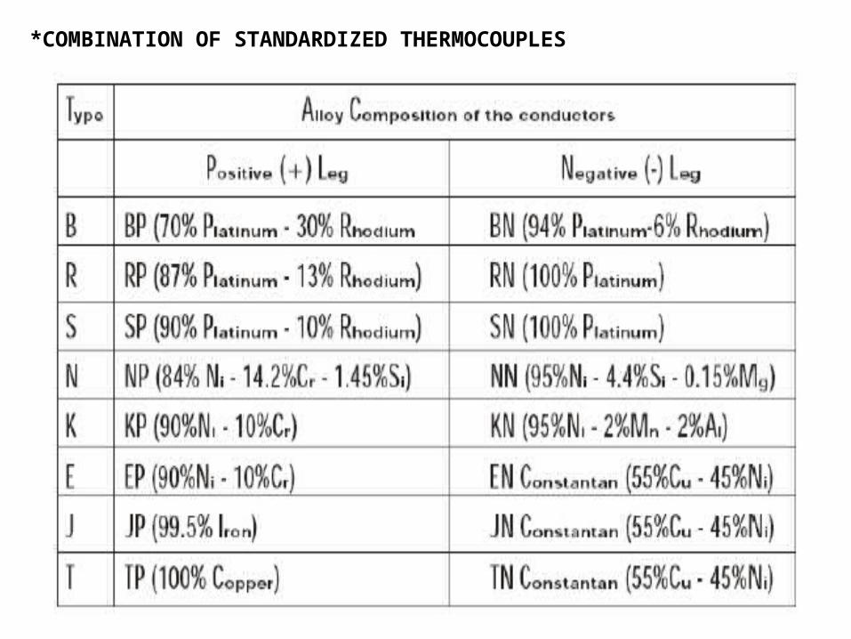
*COMBINATION OF STANDARDIZED THERMOCOUPLES
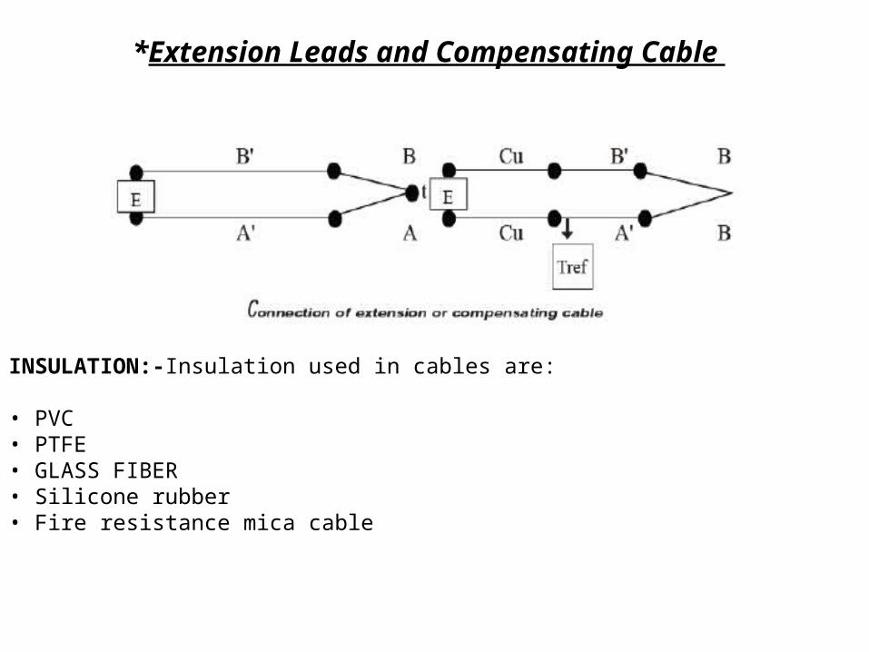
*Extension Leads and Compensating Cable
INSULATION:-Insulation used in cables are:
• PVC• PTFE• GLASS FIBER• Silicone rubber• Fire resistance mica cable
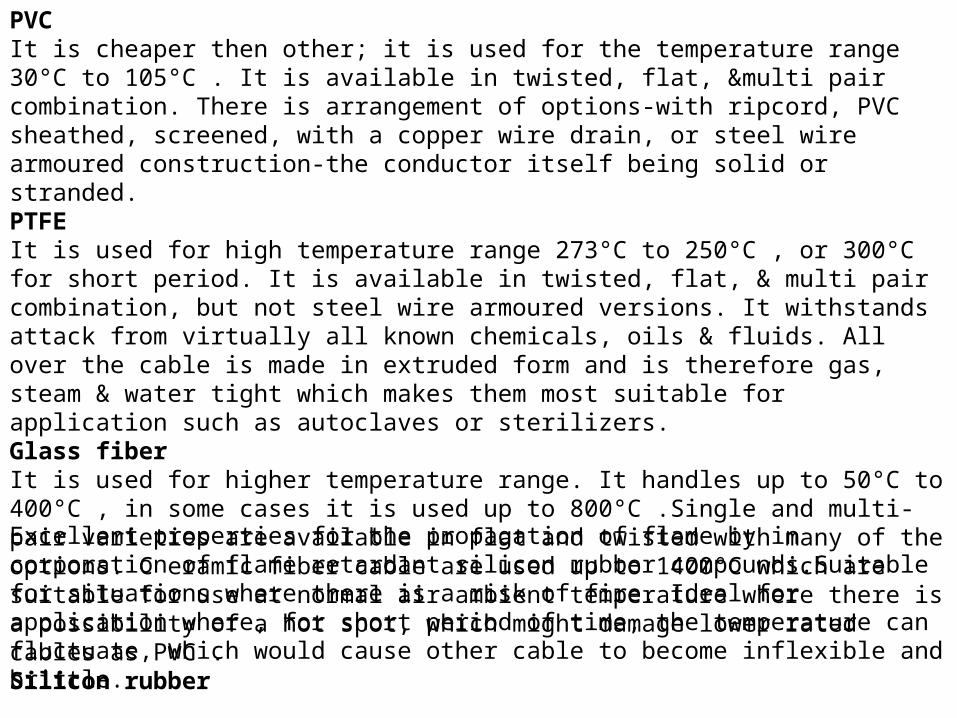
PVCIt is cheaper then other; it is used for the temperature range 30°C to 105°C . It is available in twisted, flat, &multi pair combination. There is arrangement of options-with ripcord, PVC sheathed, screened, with a copper wire drain, or steel wire armoured construction-the conductor itself being solid or stranded.PTFEIt is used for high temperature range 273°C to 250°C , or 300°C for short period. It is available in twisted, flat, & multi pair combination, but not steel wire armoured versions. It withstands attack from virtually all known chemicals, oils & fluids. All over the cable is made in extruded form and is therefore gas, steam & water tight which makes them most suitable for application such as autoclaves or sterilizers.Glass fiberIt is used for higher temperature range. It handles up to 50°C to 400°C , in some cases it is used up to 800°C .Single and multi-pair varieties are available in flat and twisted with many of the options. C eramic fiber cable are used up to 1400°C which are suitable for use at normal air ambient temperature where there is a possibility of a hot spot, which might damage lower rated cables as PVC .Silicon rubber Excellent properties for the propagation of flame by in corporation of flame retardant silicon rubber compounds.Suitable for situations where there is a risk of fire. Ideal for application where, for short period of time, the temperature can fluctuate, which would cause other cable to become inflexible and brittle.
Fire resistance mica cableResistance to a temperature of 750°C for at least three hours in accordance with the flame test requirement.Essential for situations where it is of strategic importance to ensure that the cable continues to function during a major crisis-involving fire. The cable incorporates a high temperature rated MIC A glass tape with a XLPE insulation on the cores and low smoke and fume material on the bedding and/ or outer sheath. Sheath material used is halogen free.Color-coding &specificationExtension lead & compensating cable are distinguished by color code and letters, to ease identification of the whole circuit. Although the code used to be different from country to country, standard color has been adopted for all standard thermocouple.B S 4937 part 30(1993) provides standards of coding. In this there is no difference between extension & compensating cable-color codes. With compensating cable, the different alloy used is distinguished by KC A &Armoured flame retardant PVCArmoured flame retardant PVC is extremely useful where there is a need to run a number of thermocouple signals back to instrument. All cable incorporate insulated cores, bedding and overall sheath in flame retardant PVC , which has good properties for the reduced propagation of flame. The mechanical properties of these cables meet the requirement of BS EN 60811:1995.Non-Armoured flame retardant PVCNon Armoured flame retardant PVC is extremely useful where there is a need to run a number of thermocouple signals back to instrument. All cable incorporate insulated cores, bedding and overall sheath in flame retardant PVC , which has good properties for the reduced propagation of flame. The mechanical properties of these cables meet the requirement of BS EN 60811:1995.
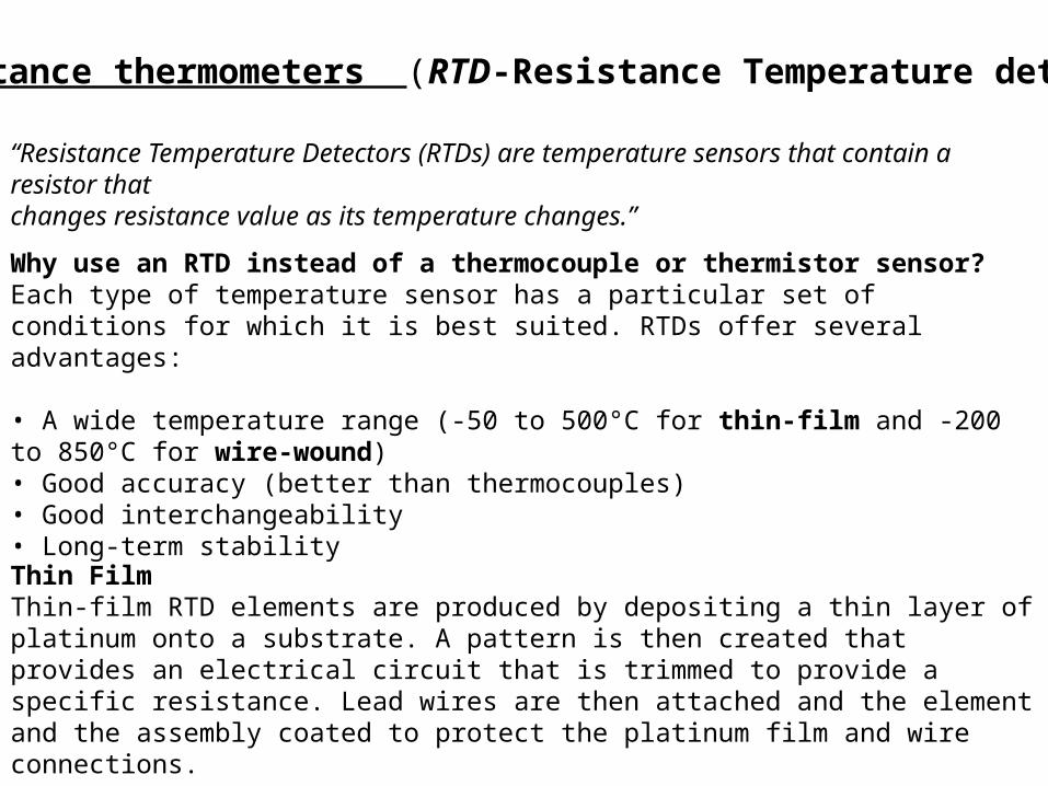
b) Resistance thermometers (RTD-Resistance Temperature detectors)
“Resistance Temperature Detectors (RTDs) are temperature sensors that contain a resistor thatchanges resistance value as its temperature changes.”
Why use an RTD instead of a thermocouple or thermistor sensor?Each type of temperature sensor has a particular set of conditions for which it is best suited. RTDs offer several advantages:
• A wide temperature range (-50 to 500°C for thin-film and -200 to 850°C for wire-wound)• Good accuracy (better than thermocouples)• Good interchangeability• Long-term stability
Thin FilmThin-film RTD elements are produced by depositing a thin layer of platinum onto a substrate. A pattern is then created that provides an electrical circuit that is trimmed to provide a specific resistance. Lead wires are then attached and the element and the assembly coated to protect the platinum film and wire connections.
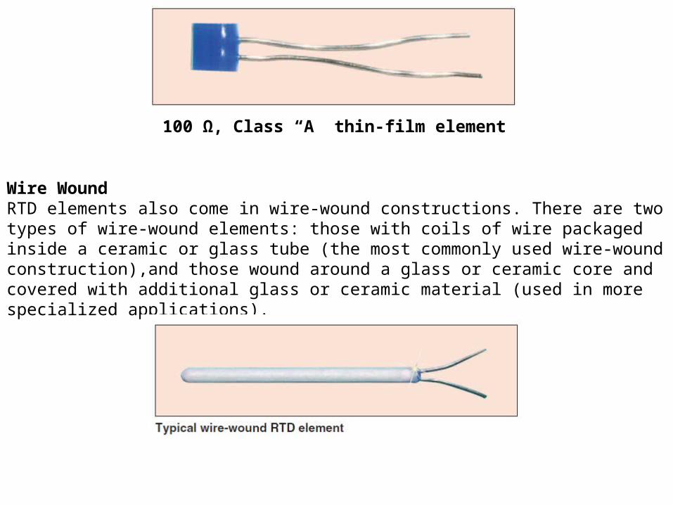
100 Ω, Class “A” thin-film element
Wire WoundRTD elements also come in wire-wound constructions. There are two types of wire-wound elements: those with coils of wire packaged inside a ceramic or glass tube (the most commonly used wire-wound construction),and those wound around a glass or ceramic core and covered with additional glass or ceramic material (used in more specialized applications).
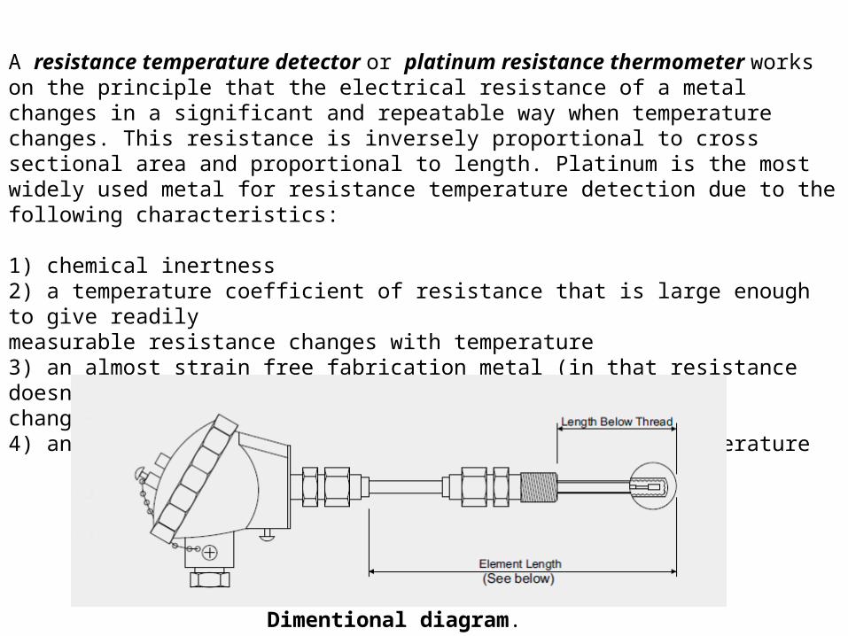
A resistance temperature detector or platinum resistance thermometer works on the principle that the electrical resistance of a metal changes in a significant and repeatable way when temperature changes. This resistance is inversely proportional to cross sectional area and proportional to length. Platinum is the most widely used metal for resistance temperature detection due to the following characteristics:
1) chemical inertness2) a temperature coefficient of resistance that is large enough to give readilymeasurable resistance changes with temperature3) an almost strain free fabrication metal (in that resistance doesn’t drasticallychange with strain)4) an almost linear relation between resistance and temperature
Dimentional diagram.
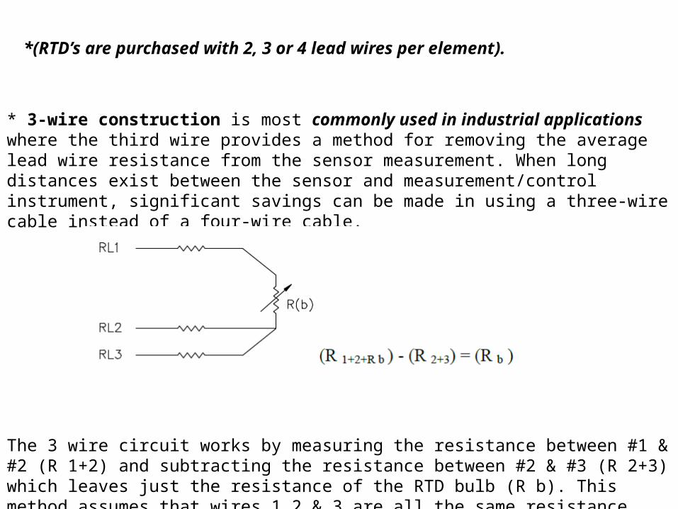
* 3-wire construction is most commonly used in industrial applications where the third wire provides a method for removing the average lead wire resistance from the sensor measurement. When long distances exist between the sensor and measurement/control instrument, significant savings can be made in using a three-wire cable instead of a four-wire cable.
The 3 wire circuit works by measuring the resistance between #1 & #2 (R 1+2) and subtracting the resistance between #2 & #3 (R 2+3) which leaves just the resistance of the RTD bulb (R b). This method assumes that wires 1,2 & 3 are all the same resistance
*(RTD’s are purchased with 2, 3 or 4 lead wires per element).
RTD RESISTANCE’S Although RTD’s are typically ordered as 100 Ohm Platinum sensors, other resistance’s (200 Ohm, 500 Ohm, 1000 Ohm, etc.) and materials (Nickel, Copper, Nickel Iron) can be specified.
TEMPERATURE COEFFICIENT Temperature coefficient for RTD’s is the ratio of the resistance change per 1 deg. change in temperature over a range of 0 - 100 deg. C. This ratio is dependent on the type and purity of the material used to manufacture the element. Most RTD’s have a positive temperature coefficient which means the resistance increases with an increase in temperature. The temp. coeff. for pure platinum is .003926 ohm/ohm/deg. C. The normal coefficient for industrial RTD’s is .00385 ohm/ohm/deg. C per the DIN std. 43760 -1980 & IEC 751 - 1983.
SELF-HEATING Since RTD’s are a resistor, they will produce heat when a current is passed through them. The normal current limit for industrial RTD’s is 1 mA. Thin film RTD’s are more susceptible to self-heating so 1 mA should not be exceeded. Wire wound RTD’s can dissipate more heat so they can withstand more than 1 mA. The larger the sheath or the more insulation there is the better chance there will be an error caused by self heating.
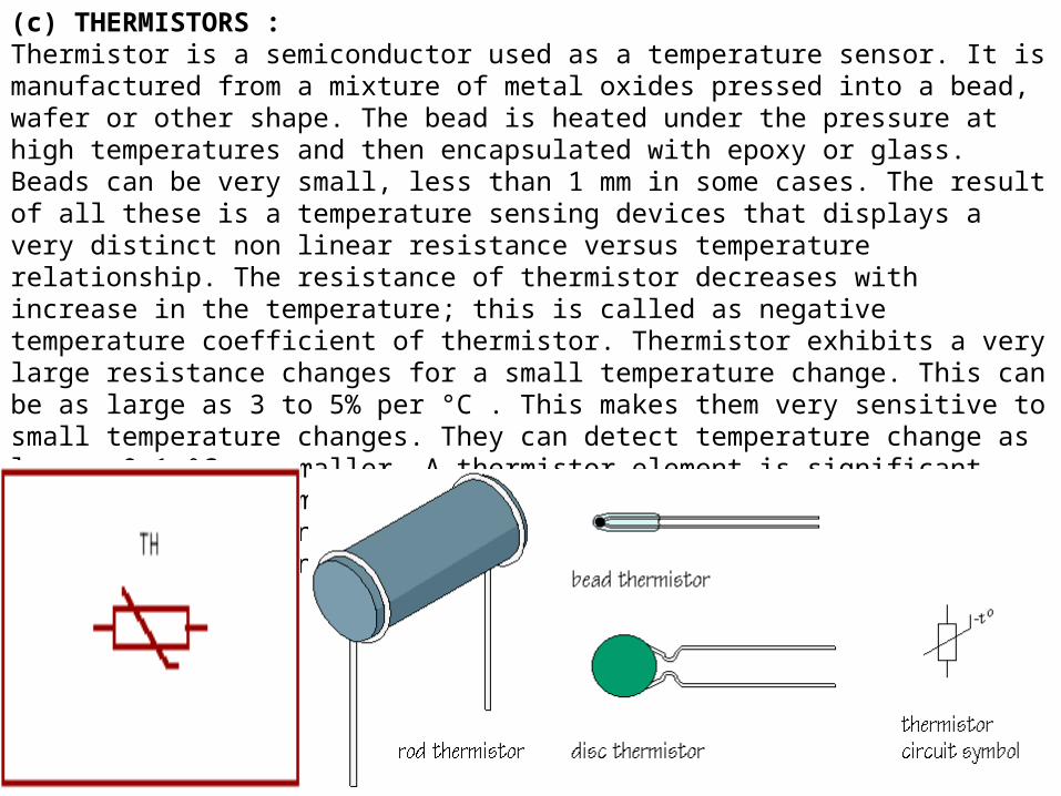
(c) THERMISTORS :Thermistor is a semiconductor used as a temperature sensor. It is manufactured from a mixture of metal oxides pressed into a bead, wafer or other shape. The bead is heated under the pressure at high temperatures and then encapsulated with epoxy or glass. Beads can be very small, less than 1 mm in some cases. The result of all these is a temperature sensing devices that displays a very distinct non linear resistance versus temperature relationship. The resistance of thermistor decreases with increase in the temperature; this is called as negative temperature coefficient of thermistor. Thermistor exhibits a very large resistance changes for a small temperature change. This can be as large as 3 to 5% per °C . This makes them very sensitive to small temperature changes. They can detect temperature change as low as 0.1 °C or smaller. A thermistor element is significant smaller in size compared to RTDs. The sensitivity of thermistors to temperature change and their small size make it ideal for use in medical equipment.
2) Non-contact method:-This method is used when the body (whose temperature is to be measured) & the sensor (which is measuring the temperature) are not allowed to remain in contact with each other.
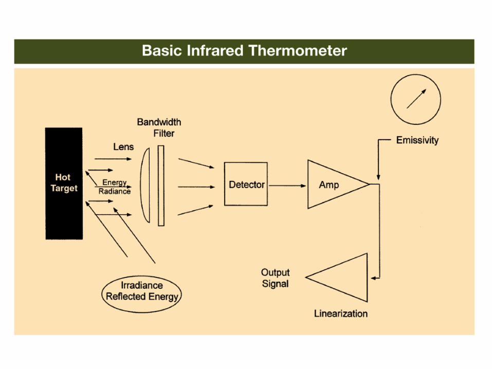
i) Infrared sensors & Pyrometers. ii) Thermal imagers.i) Infrared sensors & Pyrometers.
Infra red sensors & Pyrometer, now a day is the most common non contact temperature instrument in the industrial applications as it is easy to operate and use if the working principle is known to the user. Infra red sensor & Pyrometer measures the temperature of the object without being in the contact of the body but how is it possible? The answer is here, every object whose temperature is above absolute zero (-273.15K) emits radiation. This emission is heat radiation and its wavelength/frequency depends upon the temperature. So, this property of emission is used when the temperature is to be measured via non contact method. The term infra red radiation is also in use because the wavelength of the majority of this radiation lies in the electromagnetic spectrum above the visible red light which is in the infra red region. Similar to the radio broadcasting where emitted energy from a transmitter is captured by a receiver via anantena and then transformed into sound waves, the emitted heat radiation of an object is received by detecting devices and transformed into electric signals, and in this way the temperature of an object is measured through non contact temperature measuring instruments.
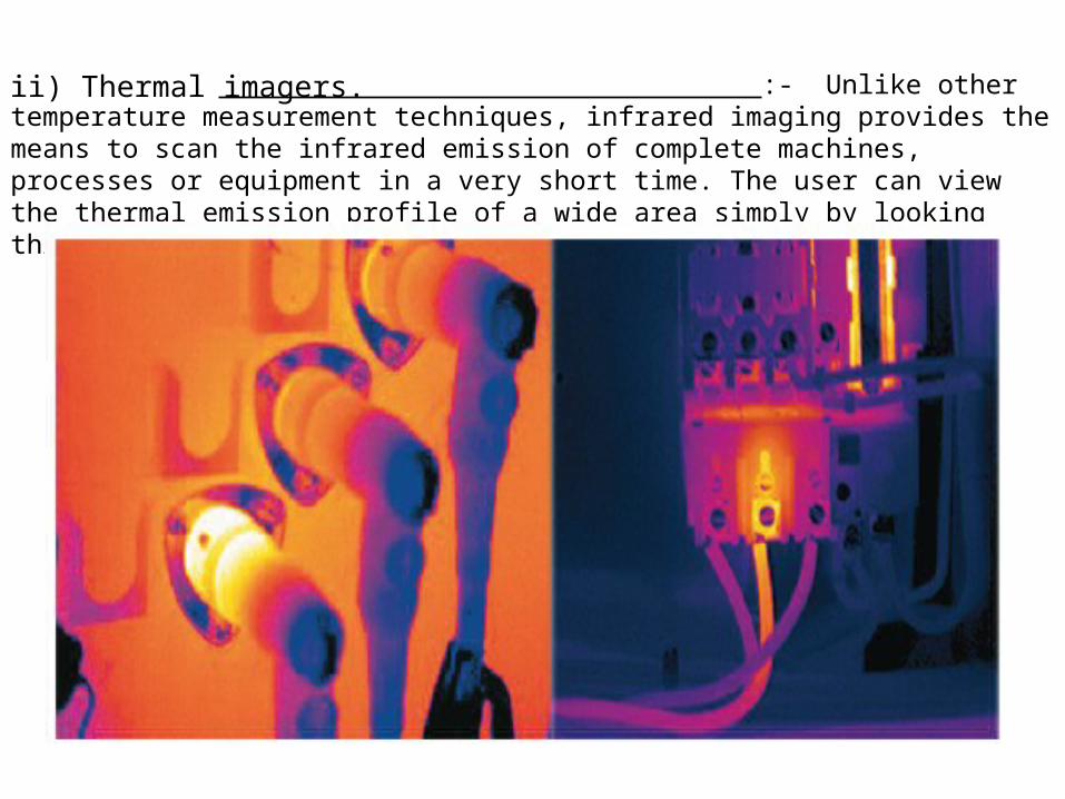
ii) Thermal imagers. :- Unlike other temperature measurement techniques, infrared imaging provides the means to scan the infrared emission of complete machines, processes or equipment in a very short time. The user can view the thermal emission profile of a wide area simply by looking through the instrument's optics.