Embed Size (px)
Citation preview

Lecture 5:
Digital multi-meter & Oscilloscope
1

• DMM are used for the measurement of DC & AC Voltages – current - resistance - BJT (beta test) - diode test - short circuit test.
• The dial sets the function and the Range. The range determines the position of the decimal point on the LCD and this determines how refined, or precise, your reading is. This is called resolution.
• DMMs have high input impedance (~10MΩ), which will not load down sensitive circuits.
2
Digital Multi-meter (DMM)

• In its basic mode, DMM is only able to measure DC voltage. To measure current or resistance, they are converted into voltage.
• Also to measure AC voltage, AC-DC conversion is required.
• A major component of DMM is the circuitry that converts the analog voltage being measured into a digital quantity. A simple and cheap circuit for this purpose is the Ramp-type digital voltmeter system shown next.
3
Digital Multi-meter (DMM)

Ramp-type Analog-to-digital conversion within an DMM
4
3.5 digit display

Ramp-type Digital Voltmeter System• When the voltage to be measured, Vin, is applied to the input terminals of the
DMM, both a ramp waveform and a clock are generated.
• The ramp is compared with Vin. As long as it is less than Vin, the comparator output is HIGH enabling the AND gate and disabling the latch circuit.
• When the ramp equals Vin, the comparator output will change from HIGH to LOW, disabling the AND gate and hence the counter will stop. The number of counts made by the counter will be proportional to the value of the input voltage being measured. The negative going edge of the comparator output triggers the latch to connect the drivers/decoders to the counting circuit so that the counter output is decoded and displayed.
• The role of the latch circuit is to isolate the display from the counting circuit during the time when counting is in progress. Otherwise, the display would be virtually unreadable. 5

Some notes on measurements with a DMM
6

AC Voltage Measurement• Using the AC voltage function, the DMM can
be used to measure the RMS value of a pure sine wave signal.
• Remember: the RMS of an AC signal is the equivalent DC voltage that dissipates the same heat (energy) as the AC signal.
• Most DMM are average responding. That is, they truly measure the average value of the signal. For sine wave, the RMS value is calculated according to the relation:
RMS = 1.1 x Average
• Therefore, measuring complex waveforms (other than pure sine wave) will give wrong RMS value. A True RMS meter is needed in this case!
7
T
T
T
dttvT
dttvT
dttvT
0
2
0
2
0
)(1
)(1
)(1
Average or Mean
Mean Square
Root Mean Square

Current measurements• Current measurement is the most potentially hazardous measurement made
with a multimeter because the meter now is a part of the circuit.
• To measure current with a DMM, turn the power off. Break or open the circuit, connect the meter in series with the circuit, and re-establish power.
• Although most multimeters have a maximum current capability of 10A, practically, only small currents are measured with a multimeter, such as 4-20 mA control loops found in most process control systems.
• One common mistake is to measure voltage with the test leads in the current input jacks. The input impedance of the current inputs jacks is 0.1Ω ~ 8Ω, depending on the manufacturer. This low impedance is like a short circuit. Most multimeters current input jacks are fused for protection. You will blow the fuse if you test in this manner. 8

Clamp-on meters• A safe method for measuring current is the
Clamp meter which avoids the requirement of breaking the circuit being measured.
• The meter clamps onto a current-carrying conductor, and the output reading is obtained by transformer action.
• The principle of operation is that the clamp-on jaws of the instrument act as a transformer core and the current-carrying conductor acts as a primary winding. Current induced in the secondary winding is rectified and applied to a meter.
• Although it is a very convenient instrument to use, the clamp-on meter has low sensitivity and the minimum current measurable is usually about 1A.
9

Resistance measurements • To measure resistance, disconnect one lead of
the resistor from the circuit or turn the circuit off. Otherwise the circuit may damage the meter.
• Place the test leads on each side of the resistor.
• When you first place the meter in the (Ω) function the meter will give a display of “OL” or “1 ___” indicating an infinite reading. Therefore, you should choose a suitable range with the dial.
• Note that other components in parallel with the resistor being measured will have an effect on the measurement.
10
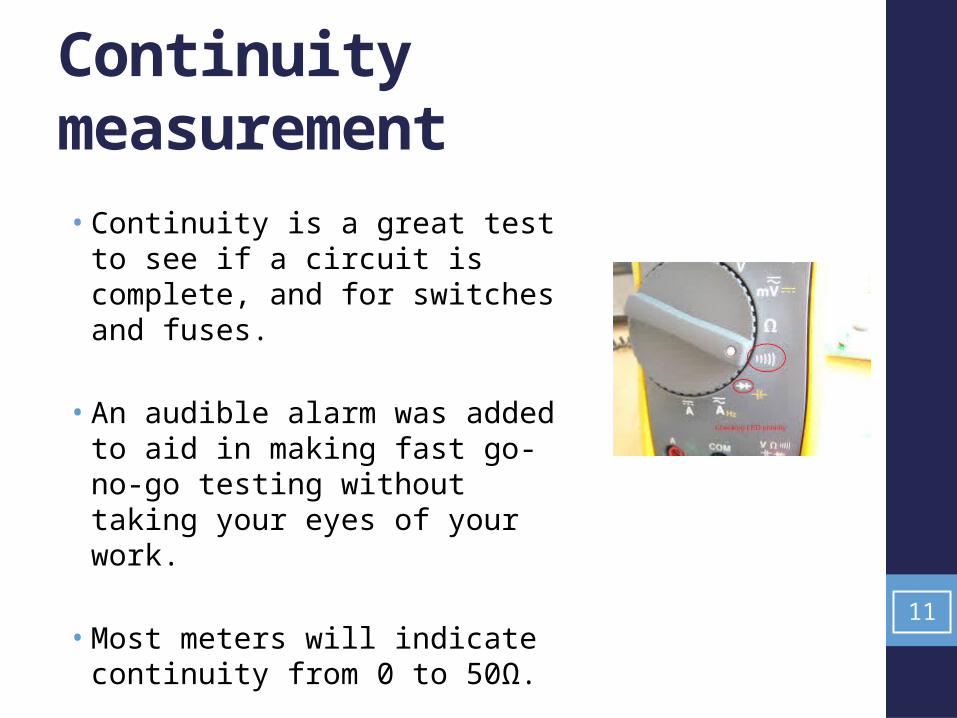
Continuity measurement
• Continuity is a great test to see if a circuit is complete, and for switches and fuses.
• An audible alarm was added to aid in making fast go-no-go testing without taking your eyes of your work.
• Most meters will indicate continuity from 0 to 50Ω.
11

Diode test with a DMM
• To test a diode with a DMM, the diode function applies an appropriate voltage and then measures the voltage drop across the diode.
• In forward direction, the voltage drop should measure around 0.5±0.2V while in the reverse direction, you should see an OL on the display.
• Some meters display the maximum reverse voltage applied to the diode. In this case, you would see a reading of around 3 volts.
12

The Oscilloscope• The scope graphically displays a time varying voltage
waveform. • The vertical (Y) axis represents voltage and the horizontal (X)
axis represents time. • This simple graph can tell you many things about a signal
waveform such as: amplitude, frequency, period, phase, DC and AC components, noise, shape, etc.
13

The digital storage oscilloscope (DSO)
• DSO acquires the waveform as a series of samples and uses an analog-to-digital converter (ADC) to convert these samples into digital words. These points are stored in memory and then displayed on the screen, using interpolation to smooth the waveform shape between data points.
• DSOs allow you to capture and view events that may happen only once, known as transients, even when the signal disappears.
14
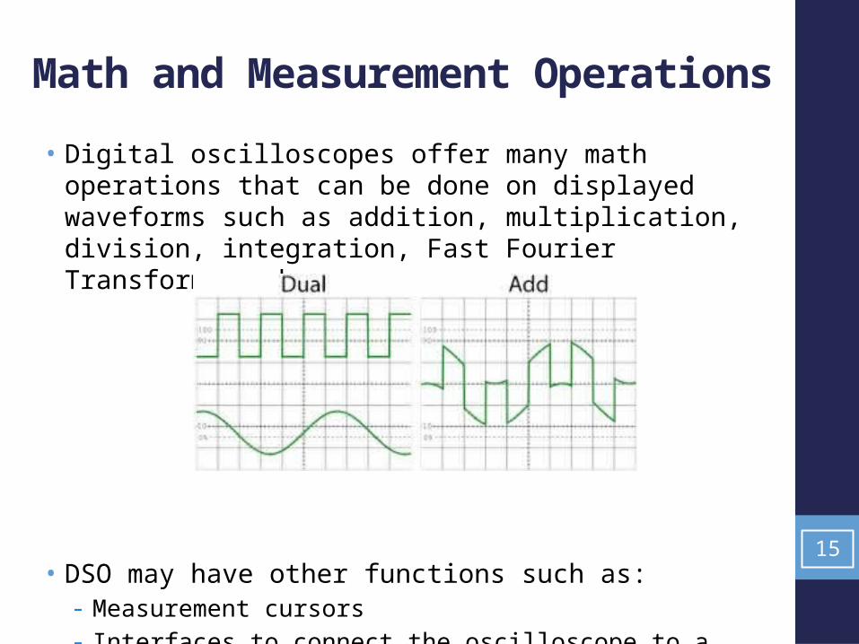
Math and Measurement Operations
• Digital oscilloscopes offer many math operations that can be done on displayed waveforms such as addition, multiplication, division, integration, Fast Fourier Transform, and more.
• DSO may have other functions such as: - Measurement cursors- Interfaces to connect the oscilloscope to a computer.
15

Oscilloscope front panel• An oscilloscope’s front panel includes a display screen and the
knobs, buttons, and switches used to control signal acquisition and display.
• The front panel also includes input connectors to which the probes are connected. One strong merit of the oscilloscope is its high input impedance, typically 1MΩ, which means that the instrument has a negligible loading effect in most measurement situations.
16
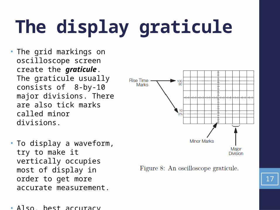
The display graticule • The grid markings on
oscilloscope screen create the graticule. The graticule usually consists of 8-by-10 major divisions. There are also tick marks called minor divisions.
• To display a waveform, try to make it vertically occupies most of display in order to get more accurate measurement.
• Also, best accuracy seems to display at least two cycles horizontally. 17

18
Main Oscilloscope Components
• Vertical display controlsScales the input voltage to set the size and position of the waveform.
• Horizontal display controls Sets the “sweep rate” (time / division) and adds a horizontal position control.
• Trigger System and controls The trigger stabilizes the waveform by controlling where, on a waveform’s voltage and slope, the display trace begins each time.

Waveform measurementsVoltage measurements • Vp-p = (VOLTS/DIV)*(Number of divisions from peak to peak)
Period and Frequency measurements • T = (TIME/DIV)*(Number of divisions/cycle) • f = 1/T Frequency and Period
Phase
19

Example
20
Waveform A: Vp-p = 0.1*4.6 = 0.46V
T= 0.5*(8.8/2) = 2.2 ms f = 1/T = 545.6 Hz.
Waveform B: Vp-p = 0.1*2 = 0.2V
T= 0.5*(8.8/6) = 0.733 msf = 1/T = 1.36 kHz.
TIME/DIV = 0.5ms/DIV VOLTS/DIV = 100mV/DIV = 0.1V/DIV

Trigger System • Imagine the jumble on the
screen that would result if each sweep started at a different place on the signal.
• The trigger makes repetitive waveforms appear static on the oscilloscope display by starting each sweep at the correct point of the signal.
21

Trigger Level and Slope
• The trigger point is determined by the level and slope.
• The level control determines the voltage value of the trigger point.
• The slope control determines whether the trigger point is on the rising (positive) or the falling (negative) edge of a signal.
22

Trigger Modes: Auto vs. Normal
• In normal mode the oscilloscope only sweeps if the input signal reaches the trigger point; otherwise the display will be frozen on the last acquired waveform.
• In Auto mode the oscilloscope sweeps, even without a trigger. This ensures that the display will not be frozen if the signal does not cause a trigger.
• In practice, you will probably start with auto mode because it requires less adjustment and then use normal mode because it lets you see just the signal of interest. 23

Trigger Hold-off
24
• This feature is useful when you are displaying complex waveform shapes so that the oscilloscope only triggers on an eligible trigger point.
• Trigger hold-off is an adjustable period of time after a valid trigger during which the oscilloscope cannot trigger.

Input Coupling (DC, AC, or ground) • DC coupling shows all of an input signal. • AC coupling blocks the DC component of a signal so that you see the
waveform centered around zero volts. • AC coupling is useful when the entire signal (AC+DC) is too large for
the volts/div setting. • The ground setting disconnects the input signal from the vertical
system, which lets you see a horizontal line on the screen that represents zero volts.
25

• The most important specifications of an oscilloscope are its bandwidth, its rise time and its accuracy.
• The bandwidth is defined as the maximum frequency over which the oscilloscope amplifier gain is within -3dB of its peak value. The -3dB point is where the gain is 0.707 times its maximum value.
• Therefore, when applied to signal-amplitude measurement, the oscilloscope is only usable at frequencies up to about 0.3 times its specified bandwidth.
26
The bandwidth

• The rise time is the transit time between the 10% and 90% levels of the response when a step input is applied to the oscilloscope.
• Oscilloscopes are normally designed such that:
Bandwidth x Rise time = 0.35
• Thus, for a bandwidth of 100 MHz,
Rise time = 0.35/108 = 3.5 ns. 27
The rise time

Pulse Measurements• In many applications, the details of a pulse shape are
important. • Pulses can become distorted and cause a digital circuit to
malfunction, and the timing of pulses in a pulse train is often significant.
• Standard pulse measurements are pulse width and pulse rise time.
28

Pulse width and rise time Measurements
• Rise time is the time a pulse takes to go from a low to high voltage. By convention, the rise time is measured from 10% to 90% of the full voltage of the pulse. This eliminates any irregularities at the pulse’s transition corners.
• Pulse width is the time the pulse takes to go from low to high and back to low again. By convention, the pulse width is measured at 50% of full voltage.
• Pulse measurements often require fine-tuning the triggering. To become an expert at capturing pulses, you should learn how to use trigger hold-off to display complex signals and time/div to see fine details of a fast pulse.
29

References
• The DMM material is taken from the following source: “The Basics of Digital Multimeters A guide to help you understand the basic Features and Functions of a Digital Multimeter.” by Patrick C Elliott, IDEAL Industries, Inc. , January 2010, Version 1.
• The material on Oscilloscopes is taken from the tutorial "XYZs of Oscilloscopes" by Tektronix Inc.
30