Embed Size (px)
Citation preview

ARC341 – Structural Analysis II Lecture 4: Sections MM5.1 – MM5.4
MM5.1) Introduction MM5.2) Shear and Bending Moment Diagrams MM5.3) Load, Shear, and Moment Relationship MM5.4) Design of Prismatic Beams for Bending
ARC 341 – Structural Analysis II Dr. Ammar T. Al-Sayegh

MM5.1) Introduction Design of any structural member requires an investigation of the
loading acting within the member in order to be sure the material can resist this loading.
These internal loadings can be determined by using method of sections.
Consider the “simply supported” beam, which is subjected to the forces 𝐹1 and 𝐹2 and support reactions 𝐴𝑥, 𝐴𝑦 and 𝐵𝑦. If internal loadings acting on the cross section at 𝐶 are to be determined, an imaginary section is passed through the beam, cutting it into two segments
ARC 341 – Structural Analysis II Dr. Ammar T. Al-Sayegh 1

The internal loadings at the section becomes external on the free-body diagram of each segment.
ARC 341 – Structural Analysis II Dr. Ammar T. Al-Sayegh 2
Since both segment (AC and CB) were in equilibrium before the beam was sectioned, equilibrium of each segment is maintained provided rectangular force component NC and VC and a resultant couple moment MC are developed at the section.
These loadings must be equal in magnitude and opposite in direction on each of the segments (Newton’s 3rd law).
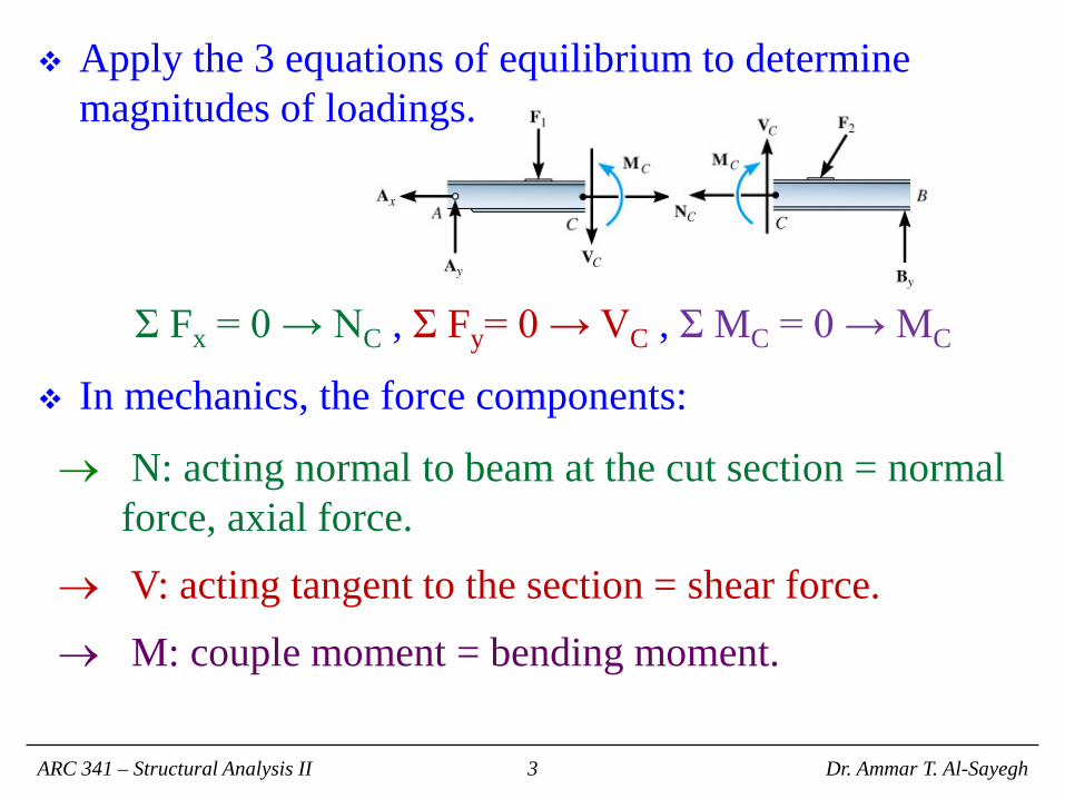
Apply the 3 equations of equilibrium to determine magnitudes of loadings.
Σ Fx = 0 → NC , Σ Fy= 0 → VC , Σ MC = 0 → MC
In mechanics, the force components:
→ N: acting normal to beam at the cut section = normal force, axial force.
→ V: acting tangent to the section = shear force. → M: couple moment = bending moment.
ARC 341 – Structural Analysis II Dr. Ammar T. Al-Sayegh 3

In 3D, the internal force and couple moment resultant will act at the section.
→ Ny: normal force.
→ Vx , Vz: shear force components.
→ My: torsional or twisting moment.
→ Mx and Mz: bending moment components.
For most applications, these resultants will act at the centroid of the cross-sections.
ARC 341 – Structural Analysis II Dr. Ammar T. Al-Sayegh 4

Procedure for Analysis 1) Determine the members support reactions so that the equilibrium equations are only used to solve for the internal loadings when the member is sectioned.
2) If member is part of a frame or machine, use techniques learned in 6.6 to determine reactions at its connections.
3) Keep all distributed loadings, couple moments, and forces acting on the member in their exact locations then pass an imaginary section through the member where the internal loading is to be determined.
4) After sectioning, draw a FBD of segment that have least number of loads on it and indicate the x, y, z components of force and moment resultants at the section.
5) If member is only subjected to coplanar forces, only N, V, and M act at section.
6) In many cases, the proper sense of unknown loadings can be determined by inspection; however, if it seems difficult, sense can be assumed.
7) Moments should be summed about an axes passing through the centroid of member’s cross-sectional area in order to eliminate the unknown normal and shear forces to obtain direct solutions for moment components.
ARC 341 – Structural Analysis II Dr. Ammar T. Al-Sayegh 5

Structural Nomenclature for Beams
ARC 341 – Structural Analysis II Dr. Ammar T. Al-Sayegh 6

Beams with Hinges When two or more beams are connected with hinges,
reaction at supports cannot be determined by the two-beam (or more) system.
In order to find the unknowns, the system must be cut at hinges and an FBD is drawn for each beam separately.
ARC 341 – Structural Analysis II Dr. Ammar T. Al-Sayegh 7

A bending moment creates normal stresses in beam, while shear force creates shearing stresses.
Typically, normal stresses dominate. Thus, the determination of normal stresses are very important in analyzing and designing a beam.
The flexure formula can be used to determine the normal stress in any section of a beam (Where’s σm?).
ARC 341 – Structural Analysis II Dr. Ammar T. Al-Sayegh 8
IMy
x −=σI
cMm =σ

Shear and Moment Diagrams Since the determination of σm
depends on M, drawing shear and moment diagrams greatly helps in finding where maximum absolute moment is located.
To draw V and M diagrams, pass a section through a point in the beam and determine the value and direction of shear and moment in that section. Note the sign.
ARC 341 – Structural Analysis II Dr. Ammar T. Al-Sayegh 9 9

Load / Shear Relationship Consider a portion 𝐶𝐶′from beam 𝐴𝐵.
𝑉𝐷 – 𝑉𝐶 = − ( area under the load curve between 𝐶 and 𝐷 ).
ARC 341 – Structural Analysis II 10
∫−=−⇒−=D
c
x
xCD wdxVVw
dxdV
wxVxwVVV −=∆∆
⇒=∆−∆−− 0)(
∑ =↑+ 0yF

Shear / Moment Relationship Consider a portion 𝐶𝐶′from beam 𝐴𝐵.
𝑀𝐷 – 𝑀𝐶 = area under the shear curve between 𝐶 and 𝐷.
ARC 341 – Structural Analysis II 11
∑ =↑+ 0'CM
02
)( =∆
∆+∆−−∆+xxwxVMMM
2)(21 xwxVM ∆−∆=∆
Vdx
dMxwVx
M=⇒∆−=
∆∆
21
∫−=−D
c
x
xCD VdxMM

Design of Prismatic Beams
1. Determine σall for the selected material. σall = σU / F.S.
2. Draw V and M diagrams and determine Mmax.
3. Determine Smin using .
4. For rectangular sections, find h and b where .
5. For rolled-steel beams, consult appropriate table in Appendix C.
Important: select the smallest weight per unit length!
ARC 341 – Structural Analysis II Dr. Ammar T. Al-Sayegh 12
all
MS
σmax
min =
2
61 bhS =
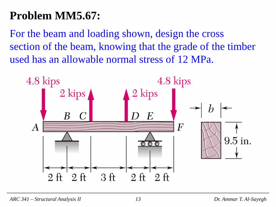
Problem MM5.67: For the beam and loading shown, design the cross section of the beam, knowing that the grade of the timber used has an allowable normal stress of 12 MPa.
ARC 341 – Structural Analysis II Dr. Ammar T. Al-Sayegh 13

Problem MM5.69: For the beam and loading shown, design the cross section of the beam, knowing that the grade of the timber used has an allowable normal stress of 12 MPa.
ARC 341 – Structural Analysis II Dr. Ammar T. Al-Sayegh 14

Problem MM5.70: For the beam and loading shown, design the cross section of the beam, knowing that the grade of the timber used has an allowable normal stress of 12 MPa.
ARC 341 – Structural Analysis II Dr. Ammar T. Al-Sayegh 15

Problem MM5.71: Knowing that the allowable stress of the steel used is 160 MPa, select the most economical wide-flange beam to support the loading shown.
ARC 341 – Structural Analysis II Dr. Ammar T. Al-Sayegh 16

Problem MM5.73: Knowing that the allowable stress of the steel used is 160 MPa, select the most economical wide-flange beam to support the loading shown.
ARC 341 – Structural Analysis II Dr. Ammar T. Al-Sayegh 17

Problem MM5.78: Knowing that the allowable stress of the steel used is 160 MPa, select the most economical S-shape beam to support the loading shown.
ARC 341 – Structural Analysis II Dr. Ammar T. Al-Sayegh 18