Embed Size (px)
Citation preview

Lecture 4 – Finite State
Machines
1 9/26/2019

Modeling Finite State Machines (FSMs)
▪ “Manual” FSM design & synthesis process:1. Design state diagram (behavior)
2. Derive state table
3. Reduce state table
4. Choose a state assignment
5. Derive output equations
6. Derive flip-flop excitation equations
▪ Steps 2-6 can be automated, given a state diagram1. Model states as enumerated type
2. Model output function (Mealy or Moore model)
3. Model state transitions (functions of current state and inputs)
4. Consider how initial state will be forced
2 9/26/2019

FSM structure
Combinational
Circuit
Memory
Elements
Inputs
XOutputs
Y
Next State
(NS)
Present State
(PS)
Clock
3 9/26/2019

Mealy Machine and Moore Machine
9/26/20194
Next State
Combinational
Logic
InputsState
RegisterOutputs
Output
Combinational
Logic
clock
Moore Machine
Next State
Combinational
Logic
Inputs
State
Register
Outputs
Output
Combinational
Logic
clock
Mealy Machine

FSM example – Mealy model
B/0 C/1 A/1
0/0
1/1 1/0
1/1
0/0
0/0
X/ZPresent
state
Input x0 1
Next state/output
A/0 A/0 C/0
A B C
A
BC
entity seqckt is
port ( x: in std_logic; -- FSM input
z: out std_logic; -- FSM output
clk: in std_logic ); -- clock
end seqckt;
5 9/26/2019

FSM example - behavioral model
architecture behave of seqckt is
type states is (A,B,C); -- symbolic state names (enumerate)
signal state: states; --state variable
begin
-- Output function (combinational logic)
z <= ‘1’ when ((state = B) and (x = ‘1’)) --all conditions
or ((state = C) and (x = ‘1’)) --for which z=1.
else ‘0’; --otherwise z=0
-- State transitions on next slide
6 9/26/2019

FSM example – state transitionsprocess (clk) – trigger state change on clock transition
beginif rising_edge(clk) then -- change state on rising clock edge
case state is -- change state according to xwhen A => if (x = ‘0’) then
state <= A;else -- if (x = ‘1’)
state <= B;end if;
when B => if (x=‘0’) thenstate <= A;
else -- if (x = ‘1’)state <= C;
end if;when C => if (x=‘0’) then
state <= C;else -- if (x = ‘1’)
state <= A;end if;
end case;end if;
end process;
7 9/26/2019

FSM example – alternative model
architecture behave of seqckt is
type states is (A,B,C); -- symbolic state names (enumerate)
signal pres_state, next_state: states;
begin
-- Model the memory elements of the FSM
process (clk)
begin
if (clk’event and clk=‘1’) then
pres_state <= next_state;
end if;
end process;
(continue on next slide)
8 9/26/2019

FSM example (alternate model, continued)
-- Model next-state and output functions of the FSM
-- as combinational logic
process (x, pres_state) -- function inputs
begin
case pres_state is -- describe each state
when A => if (x = ‘0’) then
z <= ‘0’;
next_state <= A;
else -- if (x = ‘1’)
z <= ‘0’;
next_state <= B;
end if;
(continue on next slide for pres_state = B and C)
9 9/26/2019

FSM example (alternate model, continued)
when B => if (x=‘0’) then
z <= ‘0’;
next_state <= A;
else
z <= ‘1’;
next_state <= C;
end if;
when C => if (x=‘0’) then
z <= ‘0’;
next_state <= C;
else
z <= ‘1’;
next_state <= A;
end if;
end case;
end process;
10 9/26/2019

Alternative form for output and next state
functions (combinational logic)
-- Next state function (combinational logic)
next_state <= A when ((curr_state = A) and (x = ‘0’))
or ((curr_state = B) and (x = ‘0’))
or ((curr_state = C) and (x = ‘1’)) else
B when ((curr_state = 1) and (x = ‘1’)) else
C;
-- Output function (combinational logic)
z <= ‘1’ when ((curr_state = B) and (x = ‘1’)) --all conditions
or ((curr_state = C) and (x = ‘1’)) --for which z=1.
else ‘0’; --otherwise z=0
11 9/26/2019

Moore model FSM
entity FSM is
port (CLK, EN, TDI: in bit;
RST, SHIFT: out
bit);
end entity FSM; 12 9/26/2019

Write a VHDL code using three process blocks!
13 9/26/2019
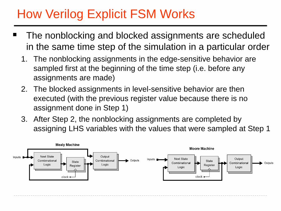
How Verilog Explicit FSM Works
▪ The nonblocking and blocked assignments are scheduled
in the same time step of the simulation in a particular order
1. The nonblocking assignments in the edge-sensitive behavior are
sampled first at the beginning of the time step (i.e. before any
assignments are made)
2. The blocked assignments in level-sensitive behavior are then
executed (with the previous register value because there is no
assignment done in Step 1)
3. After Step 2, the nonblocking assignments are completed by
assigning LHS variables with the values that were sampled at Step 1

Verilog Explicit FSM Design and Synthesis Tips
▪ Use 2 cyclic behaviors for an explicit state machine• One level-sensitive behavior for combinational logic to describe the
next state and output logic
• One edge-sensitive behavior for state flip-flops to synchronize state transition
▪ In the level-sensitive behavior for N/S and O/P• Use blocked assignments/procedural assignments “=“
• Completely specify all outputs
➢Can be achieved by initializing all outputs in the beginning
▪ In the edge-sensitive behavior for state transition• Use nonblocking assignments “<=“
➢ For state transition
➢ For register transfer of a data path
▪ Always decode all possible states in the level sensitive behavior
• To avoid unnecessary latches

Decode All Possible States!
▪ Matching simulation results between behavioral model and a
synthesized circuit does NOT guarantee that an implementation is
correct !
• Unless exercising all possible input sequences
➢ Which is almost impossible to do
• Because, if the testbench exercises the circuit only allowable input
sequences, then it is not sufficient to verify the circuit’s behaviors that are
not covered by the exercise of the testbench
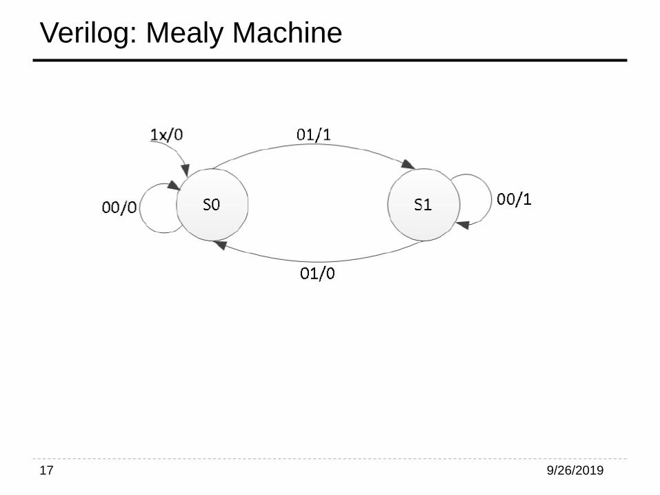
Verilog: Mealy Machine
9/26/201917

Verilog: Mealy Machine– Cont.
9/26/201918
always @(state or x)
begin
parity = 1'b0;
case(state)
S0: if(x)
begin
parity = 1; nextstate = S1;
end
else
nextstate = S0;
S1: if(x)
nextstate = S0;
else
begin
parity = 1; nextstate = S1;
end
default:
nextstate = S0;
endcase
end
endmodule
module mealy_2processes(input clk,
input reset, input x, output reg
parity);
reg state, nextstate;
parameter S0=0, S1=1;
always @(posedge clk or posedge
reset)
if (reset)
state <= S0;
else
state <= nextstate;
*Xilinx Documentation

Verilog: Mealy Machine– Cont.
9/26/201919
*Xilinx Documentation
module mealy_3processes(input clk, input
reset, input x, output reg parity);
reg state, nextstate;
parameter S0=0, S1=1;
always @(posedge clk or posedge reset)
if (reset)
state <= S0;
else state <= nextstate;
always @(state or x) //Output Logic
begin
parity = 1'b0;
case(state)
S0: if(x)
parity = 1;
S1: if(!x)
parity = 1;
endcase
end
always @(state or x) // Nextstate Logic
begin
nextstate = S0;
case(state)
S0: if(x) nextstate = S1;
S1: if(!x) nextstate = S1;
endcase
end
endmodule

Verilog: Moore Machine
9/26/201920
*Xilinx Documentation
module mealy_3processes(input clk, input
reset, input x, output reg parity);
reg state, nextstate;
parameter S0=0, S1=1;
always @(posedge clk or posedge reset)
if (reset)
state <= S0;
else state <= nextstate;
always @(state) // Output Logic
begin
case(state)
S0: parity = 0;
S1: parity = 1;
endcase
end
always @(state or x) // Nextstate Logic
begin
nextstate = S0;
case(state)
S0: if(x) nextstate = S1;
S1: if(!x) nextstate = S1;
endcase
end
endmodule
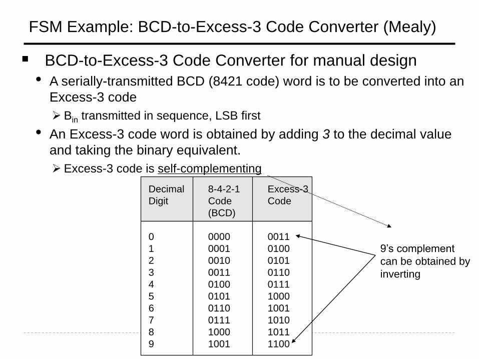
FSM Example: BCD-to-Excess-3 Code Converter (Mealy)
▪ BCD-to-Excess-3 Code Converter for manual design
• A serially-transmitted BCD (8421 code) word is to be converted into an
Excess-3 code
➢ Bin transmitted in sequence, LSB first
• An Excess-3 code word is obtained by adding 3 to the decimal value
and taking the binary equivalent.
➢ Excess-3 code is self-complementing
Decimal 8-4-2-1 Excess-3
Digit Code Code
(BCD)
0 0000 0011
1 0001 0100
2 0010 0101
3 0011 0110
4 0100 0111
5 0101 1000
6 0110 1001
7 0111 1010
8 1000 1011
9 1001 1100
9’s complement
can be obtained by
inverting
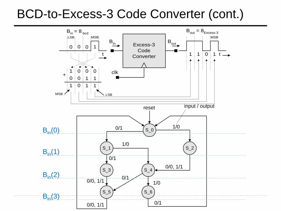
BCD-to-Excess-3 Code Converter (cont.)
Excess-3
Code
Converter
clk
Bout
= 8Excess-3
1 0 0 0+
1 1 10
Bin
= 8 bcd
Bout
0 0 1 1
1 0 1 1
LSBMSB
0 0 0 1
t
LSB MSB
t
MSB
Bin
S_5
S_0
input / output
1/00/1
0/1
0/0, 1/1
1/0
0/11/0
0/10/0, 1/1
0/0, 1/1
S_1 S_2
S_4S_3
S_6
reset
Bin(0)
Bin(1)
Bin(2)
Bin(3)

BCD-to-Excess-3 Code Converter (cont.)
module BCD_to_Excess_3b (B_out, B_in, clk, reset_b);
output B_out;
input B_in, clk, reset_b;
parameter S_0 = 3'b000, // State assignment, which may be omitted
S_1 = 3'b001, // If omitted, allow synthesis tool to assign
S_2 = 3'b101,
S_3 = 3'b111,
S_4 = 3'b011,
S_5 = 3'b110,
S_6 = 3'b010,
dont_care_state = 3'bx,
dont_care_out = 1'bx;
reg[2: 0] state, next_state;
reg B_out;

BCD-to-Excess-3 Code Converter (cont.)
always @ (posedge clk or negedge reset_b) // edge-sensitive behavior with NBAs
if (reset_b == 0) state <= S_0; else state <= next_state;
always @ (state or B_in) begin // level-sensitive behavior with blocked assignments
B_out = 0; // initialize all outputs here
case (state) // explicit states
S_0: if (B_in == 0) begin next_state = S_1; B_out = 1; end
else if (B_in == 1) begin next_state = S_2; end // Mealy machine
S_1: if (B_in == 0) begin next_state = S_3; B_out = 1; end
else if (B_in == 1) begin next_state = S_4; end
S_2: begin next_state = S_4; B_out = B_in; end
S_3: begin next_state = S_5; B_out = B_in; end
S_4: if (B_in == 0) begin next_state = S_5; B_out = 1; end
else if (B_in == 1) begin next_state = S_6; end
S_5: begin next_state = S_0; B_out = B_in; end
S_6: begin next_state = S_0; B_out = 1; end
/* default: begin next_state = dont_care_state;
B_out = dont_care_out; end */
endcase
end
endmodule

Zero Detector
▪ Asserting its output when a 0 is detected in a
stream of 1s.
9/26/201925

Zero Detector: Mealy Machine
9/26/201926
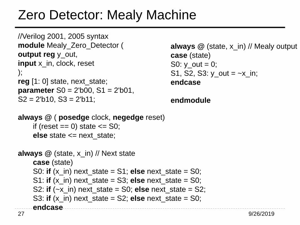
Zero Detector: Mealy Machine
9/26/201927
//Verilog 2001, 2005 syntax
module Mealy_Zero_Detector (
output reg y_out,
input x_in, clock, reset
);
reg [1: 0] state, next_state;
parameter S0 = 2'b00, S1 = 2'b01,
S2 = 2'b10, S3 = 2'b11;
always @ ( posedge clock, negedge reset)
if (reset == 0) state <= S0;
else state <= next_state;
always @ (state, x_in) // Next state
case (state)
S0: if (x_in) next_state = S1; else next_state = S0;
S1: if (x_in) next_state = S3; else next_state = S0;
S2: if (~x_in) next_state = S0; else next_state = S2;
S3: if (x_in) next_state = S2; else next_state = S0;
endcase
always @ (state, x_in) // Mealy output
case (state)
S0: y_out = 0;
S1, S2, S3: y_out = ~x_in;
endcase
endmodule

Binary Counter: Moore Machine
9/26/201928

Binary Counter: Moore Machine
▪ Write a Verilog code for Binary Counter (Moore
Machine).
9/26/201929