Embed Size (px)
Citation preview

Click to edit Master title style CE-363
Lecture - 4: Track Modulus,
Stresses in Track
Dr. Ankit Gupta, Assistant Professor
Department of Civil Engineering
National Institute of Technology Hamirpur
Lecture Outline
Track Modulus
Relief of Stress
Stresses in track: Static load condition
Stresses in track: Dynamic effects

Track Modulus
Based on Elastic Theory
Track Modulus
It is an index for stiffness of track.
Defined as load per unit length of the rail
required to produce a unit depression in
the track.
Track Modulus
Depends up on
Gauge
Type of rail section
Type and density of sleepers
Type and section of ballast
Sub-grade
Track Modulus
Recommended values of track modulus
BG = 70 to 90 kg/cm2
MG = 42 to 54 kg/cm2
NG = 30 kg/cm2

Track Modulus
Experimental Computation
Observe the deflection below sleepers
provided per rail length
Then track modulus can be calculated as
µ = P / ( x L)
Where, P = Load of engine on one rail
= average deflection, and
L = rail length

Track Modulus
Experimental Computation
Calculation
Average deflection
= Sum of deflection under sleepers / number of sleepers
= i / N
µ = P x N / (i x L) or
µ = P / (i x S)
Where, S = Average spacing between sleepers = L / N
Relief of Stresses
Can be defined as:
‘This is a state that is reached when a
group of wheel loads working close to
each other act simultaneously on the
rail.’

Relief of Stresses
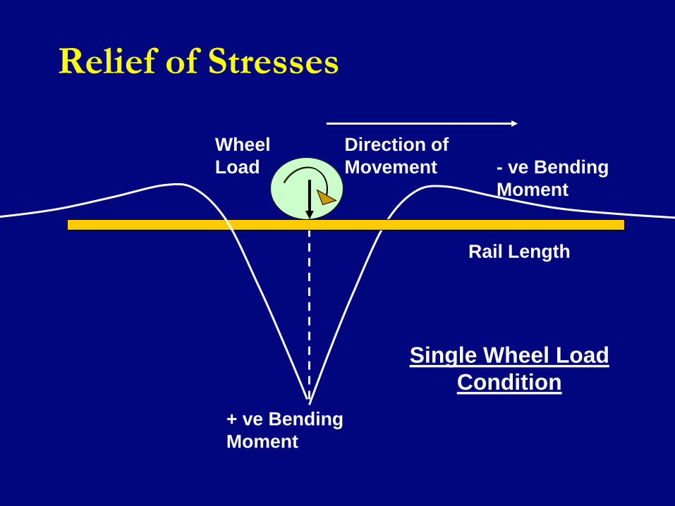
Single wheel load condition:
When a single wheel load acts on the
rail, the rail deflects at that point and a
maximum bending moment gets
produced below the center of the rail
seat.
Relief of Stresses
Single Wheel Load
Condition
Wheel
Load
+ ve Bending
Moment
Direction of
Movement - ve Bending
Moment
Rail Length

Relief of Stresses
Single wheel load condition:
This bending moment becomes negative
after the point of contra flexure. It attains
Maximum negative bending moment at
some distance from the wheel load (due
to which it is produced) and becomes
negligible at a further distance along the
rail length.

Relief of Stresses
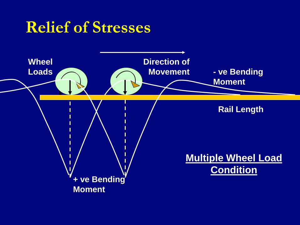
Group of wheel loads:
In case of group of wheel loads, the maximum
positive bending moment produced below the
centre of rail seat on which the wheel load
under consideration is acting gets
counteracted by the negative bending moment
produced by the adjacent wheel load.
Therefore, the net bending moment under the
wheel considered will be less than the
maximum positive bending moment.
Relief of Stresses
Multiple Wheel Load
Condition
Wheel
Loads
+ ve Bending
Moment
Direction of
Movement - ve Bending
Moment
Rail Length

Relief of Stresses
Hence, the magnitude of the relief of stress depends upon the distance of the point of contra flexure of the rail and spacing of wheels.
In case of wagons, the axle distances are very large as compared to the axle distances of the locomotives.
Also, stresses due to locomotives are higher as compared to the wagon, because of heavier weight of the locomotive.
This relief of stress under the wheel may be up to 50 percent.

Track Stresses
Forces acting on Track
Vertical dead loads and dynamic augment
Lateral Forces
Lateral movement of loads, eccentricity,
shunting etc.
Longitudinal forces
Tractive effort and braking forces
Contact stresses
Wheel and rail contact
Stresses due to surface defects
Track Stresses: Static Loads
Vertical loads
Dead load
Usually taken from axle-load diagram.
Causes bending stresses in the rail
Track Stresses: Static Loads
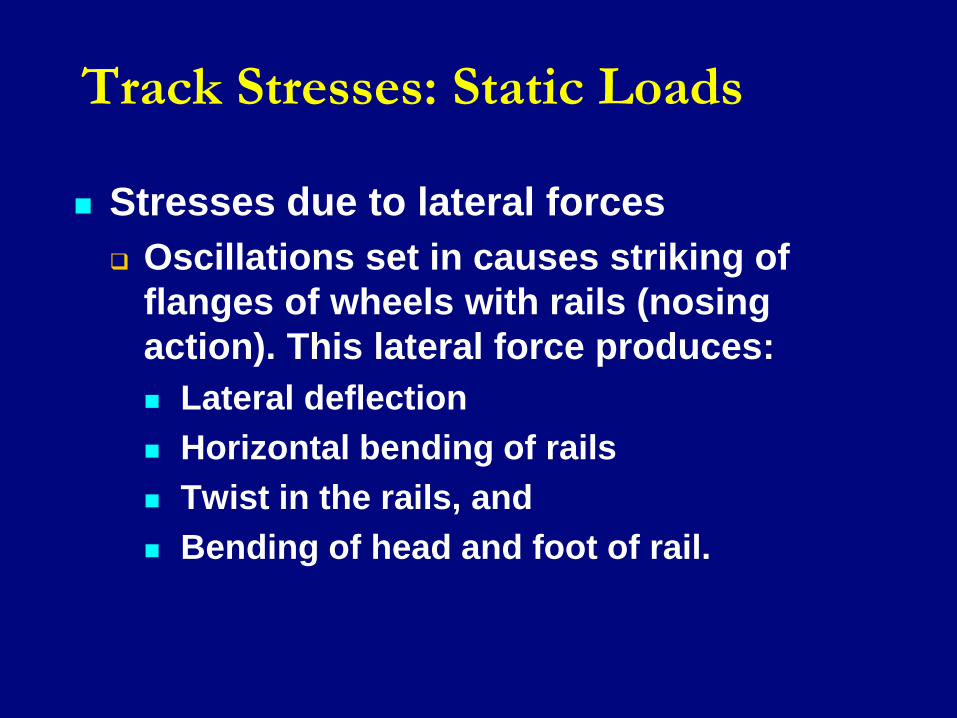
Stresses due to lateral forces
Oscillations set in causes striking of
flanges of wheels with rails (nosing
action). This lateral force produces:
Lateral deflection
Horizontal bending of rails
Twist in the rails, and
Bending of head and foot of rail.

Track Stresses: Static Loads
This is resisted by rail-sleeper fastenings,
friction between rail and sleeper and
ballast cover.
Design load against horizontal thrust on
tangent is taken as 40% of the axle load
plus 2 tons.

Track Stresses
Stresses due to longitudinal forces
Caused due to:
Tractive effort of the locomotive
Braking force of wheels; and
Temperature variation in welded rails.
Longitudinal force on account of tractive
effort for AC:
30 to 40% weight of locomotive
Track Stresses
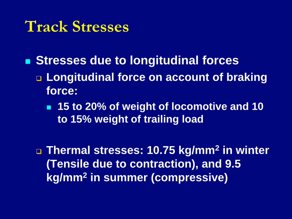
Stresses due to longitudinal forces
Longitudinal force on account of braking
force:
15 to 20% of weight of locomotive and 10
to 15% weight of trailing load
Thermal stresses: 10.75 kg/mm2 in winter
(Tensile due to contraction), and 9.5
kg/mm2 in summer (compressive)

Track Stresses
Contact Stresses between rail and wheel
Wheel and rail head are assumed to be
two cylinders with their axis at right
angles to each other and having an
elliptical contact area.
The maximum contact shear stress at the
contact point between the wheel and rail
is given by:
F = 4.13 (P/R)1/2 in kg/mm2
Track Stresses
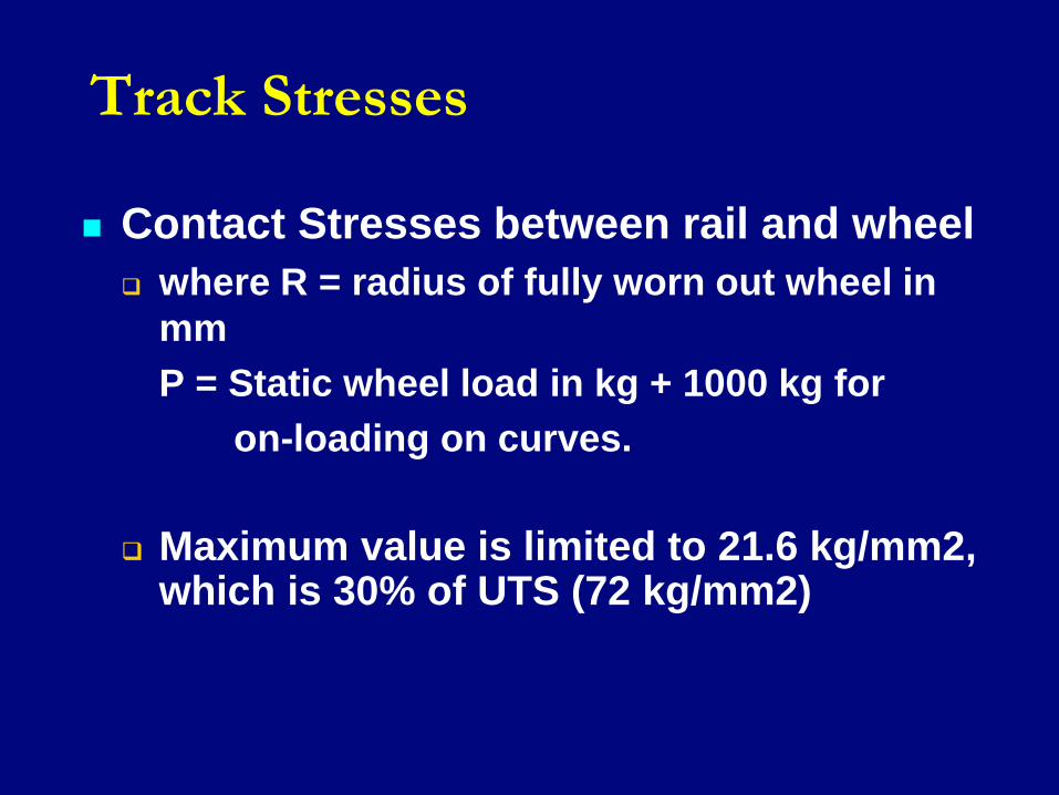
Contact Stresses between rail and wheel
where R = radius of fully worn out wheel in
mm
P = Static wheel load in kg + 1000 kg for
on-loading on curves.
Maximum value is limited to 21.6 kg/mm2, which is 30% of UTS (72 kg/mm2)

Track Stresses
Contact Stresses between rail and wheel

Track Stresses
Stresses due to surface defects
Caused due to:
Unevenness of ballast or sub grade,
Non-uniformity in the gauge, and
Level difference in the top of rails.

Track Stresses
Stresses due to surface defects
Surface defects causes deflection as high
as 1.5 times the depth of flat or low spot at
critical speed of 30 km ph.
Additional BM is also caused (~ 370 T.cm
for BG group – A route with WDM 4
locomotive).

Track Stresses
Stresses due to curves
Causes:
Lateral bending due to rigid wheel base of
the vehicles,
Excessive vertical load over the normal
wheel load on the inner or outer rail
depending upon super-elevation and
speed of the vehicle, and
Non-uniform distribution of pressure over
outer and inner wheels.

Track Stresses: Dynamic Effects
Due to Speed
The effect is measured in terms of Speed or
impact factor and is given by
= V / (18.2 õ)
Where
V = speed of train in km ph
µ = track modulus in kg/cm2

Track Stresses: Dynamic Effects
Due to Speed (New formula)
For speed up to 100 km ph
Speed factor = V2/30000
For speed above 100 km ph
Speed factor = (4.5 V2/105) – (1.5V3/107)
In case of static load, it is multiplied to wheel
load to account for dynamic effect due to speed.

Track Stresses: Dynamic Effects
Hammer Blow It is a case of steam locomotives.
Revolving masses (crank pins, connecting rods, coupled rods, bolts, etc.) in the driving and coupled wheels revolve eccentrically with the wheel.
The effect of these masses is counteracted by balancing weight placed at the opposite side to crank.
Track Stresses: Dynamic Effects
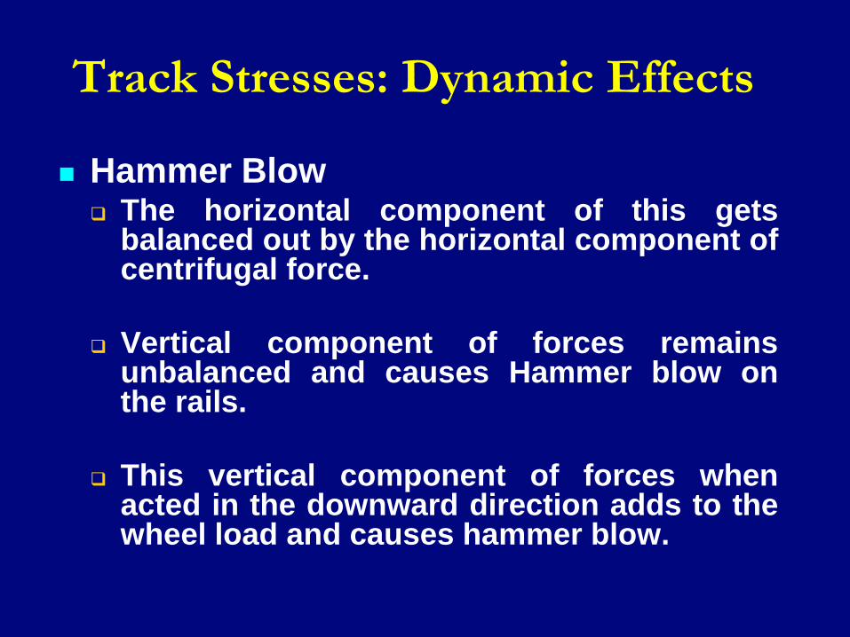
Hammer Blow The horizontal component of this gets
balanced out by the horizontal component of centrifugal force.
Vertical component of forces remains unbalanced and causes Hammer blow on the rails.
This vertical component of forces when acted in the downward direction adds to the wheel load and causes hammer blow.
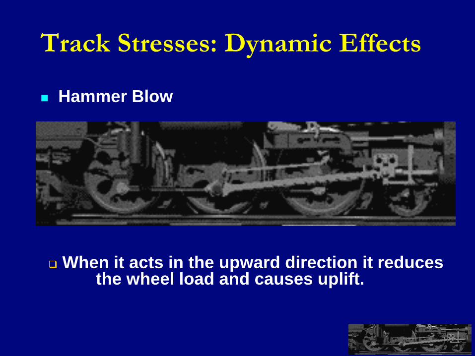
Track Stresses: Dynamic Effects
Hammer Blow
When it acts in the upward direction it reduces the wheel load and causes uplift.
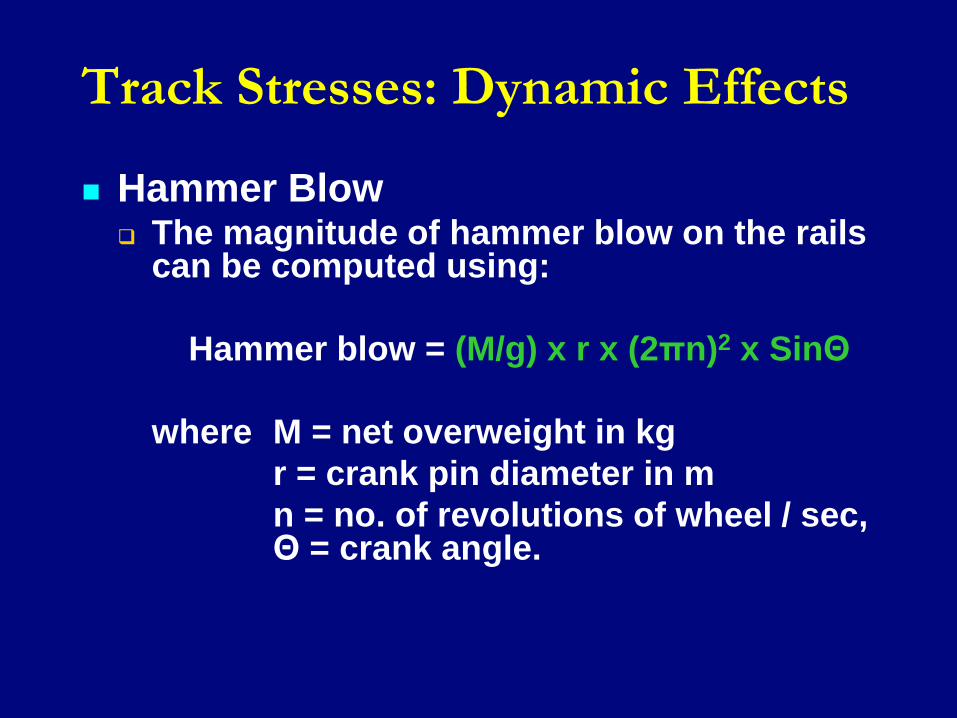
Track Stresses: Dynamic Effects
Hammer Blow The magnitude of hammer blow on the rails
can be computed using:
Hammer blow = (M/g) x r x (2πn)2 x SinΘ
where M = net overweight in kg
r = crank pin diameter in m
n = no. of revolutions of wheel / sec, Θ = crank angle.

Track Stresses: Dynamic Effects
Steam Effect
It is a case of steam locomotives.
It is caused due to steam pressure on
piston, which is transmitted to the driving
wheels through crank pins and
connecting rod.
The vertical component of crank pin and
connecting rod is at an angle with the
piston rod.
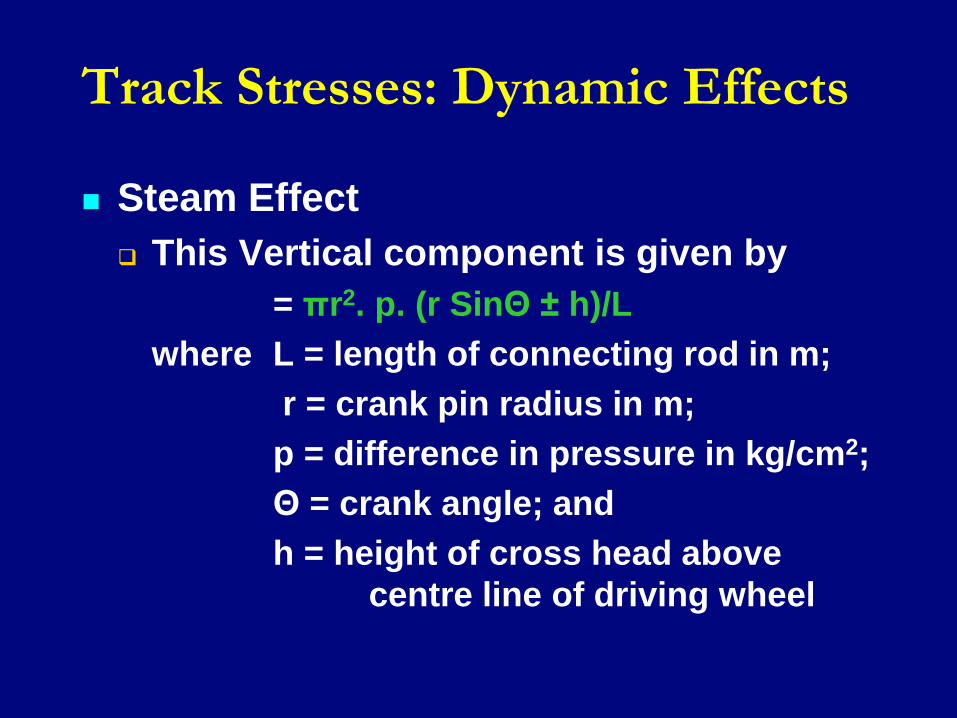
Track Stresses: Dynamic Effects
Steam Effect
This Vertical component is given by
= πr2. p. (r SinΘ ± h)/L
where L = length of connecting rod in m;
r = crank pin radius in m;
p = difference in pressure in kg/cm2;
Θ = crank angle; and
h = height of cross head above
centre line of driving wheel
Track Stresses: Dynamic Effects
Steam Effect
This force adds to the wheel load when
crank pin is in the downward direction
and subtracts the effect of the wheel
load when it is in the upward direction.
It is not in synchronization with the
hammer blow caused due to balancing
weights.

Track Stresses: Dynamic Effects
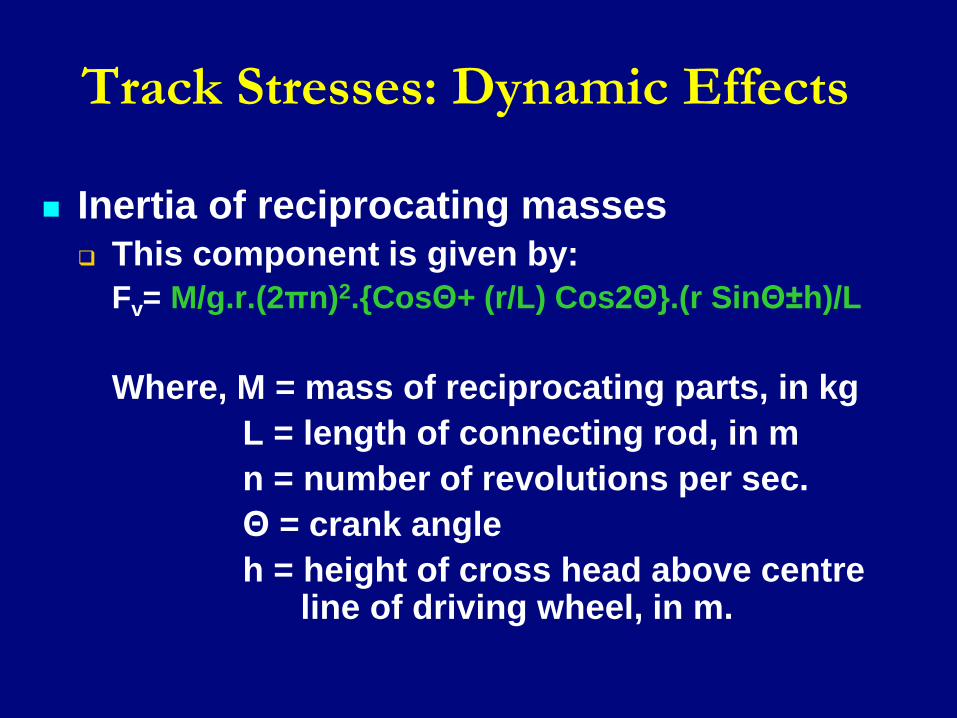
Inertia of reciprocating masses
The effect of inertia of the reciprocating masses and the acceleration caused, changes pressure on the piston and hence also changes the force in the connecting rod during the revolution of the wheel.
Track Stresses: Dynamic Effects
Inertia of reciprocating masses
This component is given by:
Fv= M/g.r.(2πn)2.{CosΘ+ (r/L) Cos2Θ}.(r SinΘ±h)/L
Where, M = mass of reciprocating parts, in kg
L = length of connecting rod, in m
n = number of revolutions per sec.
Θ = crank angle
h = height of cross head above centre line of driving wheel, in m.