Embed Size (px)
Citation preview

Electric Circuits (Fall 2017) Pingqiang Zhou
Lecture 3Circuit Theorems
10/16/2017
1
Electric Circuits (Fall 2017) Pingqiang Zhou
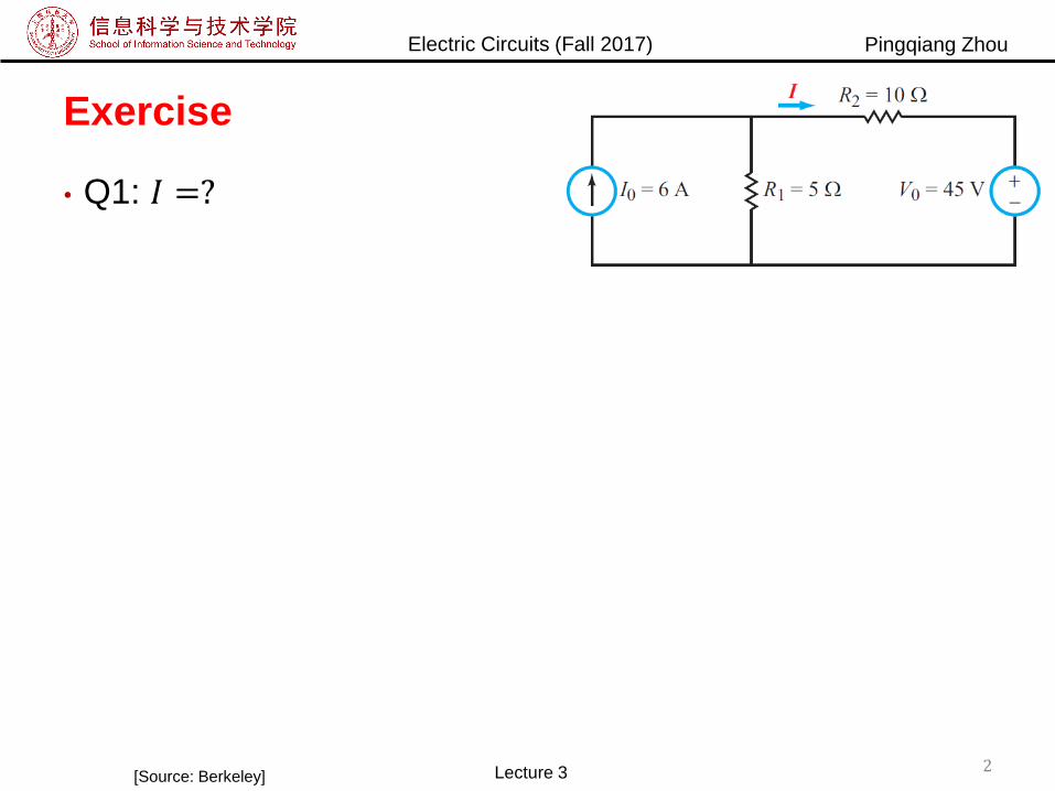
Exercise
• Q1: 𝐼 =?
2Lecture 3[Source: Berkeley]
Electric Circuits (Fall 2017) Pingqiang Zhou
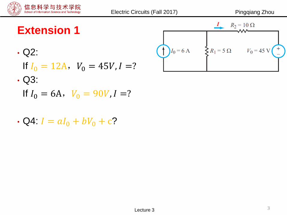
Extension 1
• Q2:
If 𝐼0 = 12A,𝑉0 = 45𝑉, 𝐼 =?
• Q3:
If 𝐼0 = 6A,𝑉0 = 90𝑉, 𝐼 =?
• Q4: 𝐼 = 𝑎𝐼0 + 𝑏𝑉0 + c?
3Lecture 3
Electric Circuits (Fall 2017) Pingqiang Zhou
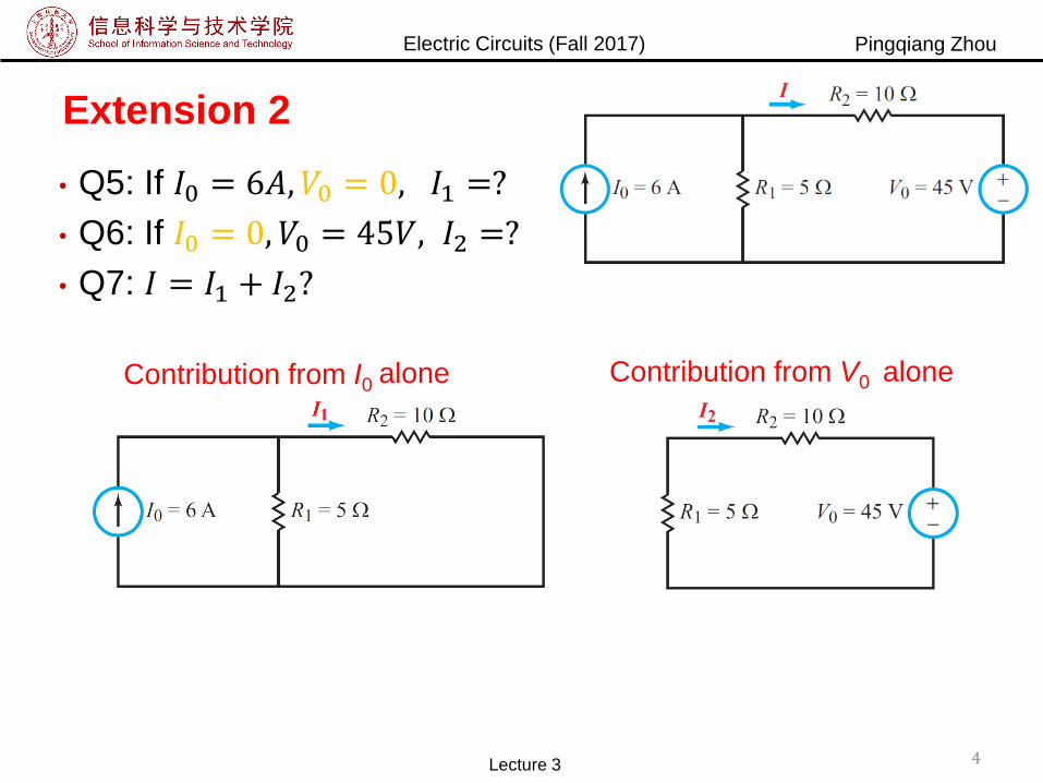
Extension 2
• Q5: If 𝐼0 = 6𝐴, 𝑉0 = 0, 𝐼1 =?
• Q6: If 𝐼0 = 0, 𝑉0 = 45𝑉, 𝐼2 =?
• Q7: 𝐼 = 𝐼1 + 𝐼2?
4Lecture 3
Contribution from I0 Contribution from V0alone alone

Electric Circuits (Fall 2017) Pingqiang Zhou
Extension 3
• Q7: If 𝑅2 = 1Ω, 𝐼 =?
• Q8: What if 𝑅2 = 5Ω?
5Lecture 3

Electric Circuits (Fall 2017) Pingqiang Zhou
Outline
• Linearity property
• Superposition
• Thevenin’s theorem
• Source transformation
• Norton’s theorem
Lecture 3 6
Electric Circuits (Fall 2017) Pingqiang Zhou
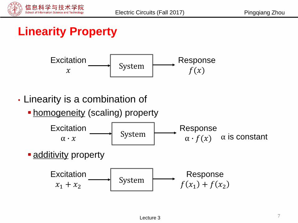
Linearity Property
• Linearity is a combination of
homogeneity (scaling) property
additivity property
SystemExcitation
𝑥Response
𝑓(𝑥)
SystemExcitation
α ∙ 𝑥Response
α ∙ 𝑓(𝑥) α is constant
SystemExcitation
𝑥1 + 𝑥2
Response
𝑓 𝑥1 + 𝑓 𝑥2
Lecture 3 7
Electric Circuits (Fall 2017) Pingqiang Zhou
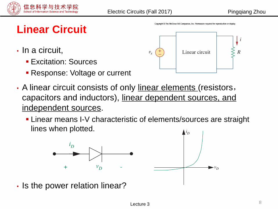
Linear Circuit
• In a circuit,
Excitation: Sources
Response: Voltage or current
• A linear circuit consists of only linear elements (resistors,capacitors and inductors), linear dependent sources, and
independent sources.
Linear means I-V characteristic of elements/sources are straight
lines when plotted.
• Is the power relation linear?
8Lecture 3

Electric Circuits (Fall 2017) Pingqiang Zhou
Exercise
• Power due to 𝐼0, 𝑃1 =?
• Power due to 𝑉0, 𝑃2 =?
• Power due to both 𝑉0 and 𝐼0, 𝑃 =?
9Lecture 3
Electric Circuits (Fall 2017) Pingqiang Zhou
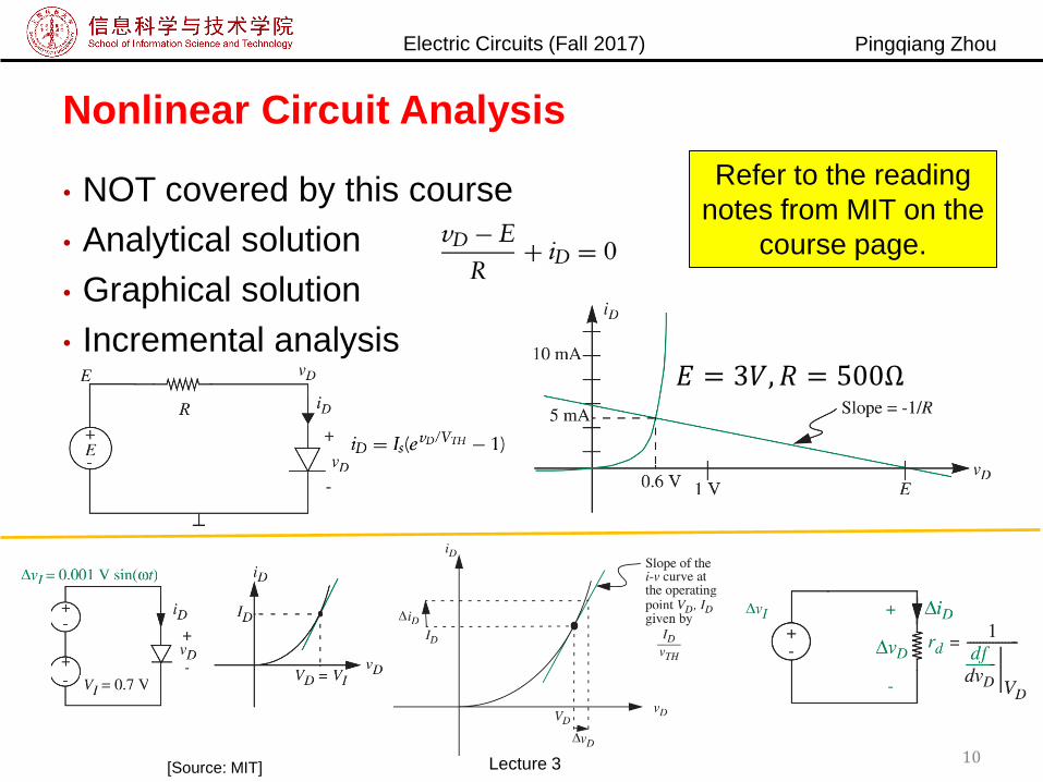
Nonlinear Circuit Analysis
• NOT covered by this course
• Analytical solution
• Graphical solution
• Incremental analysis
10Lecture 3
Refer to the reading
notes from MIT on the
course page.
𝐸 = 3𝑉, 𝑅 = 500Ω
[Source: MIT]
Electric Circuits (Fall 2017) Pingqiang Zhou
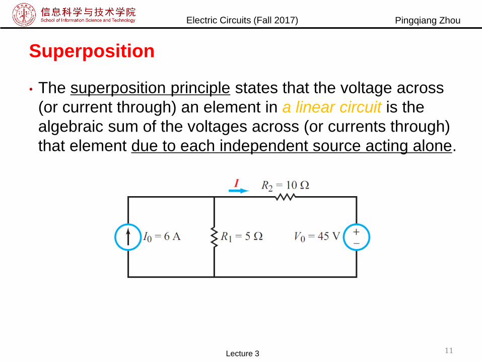
Superposition
• The superposition principle states that the voltage across
(or current through) an element in a linear circuit is the
algebraic sum of the voltages across (or currents through)
that element due to each independent source acting alone.
Lecture 3 11
Electric Circuits (Fall 2017) Pingqiang Zhou
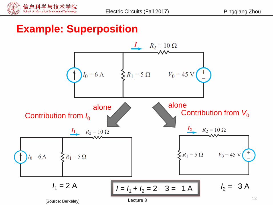
Example: Superposition
Contribution from I0Contribution from V0
I1 = 2 A I = I1 + I2 = 2 ‒ 3 = ‒1 A
alone alone
I2 = ‒3 A
[Source: Berkeley] Lecture 3 12
Electric Circuits (Fall 2017) Pingqiang Zhou
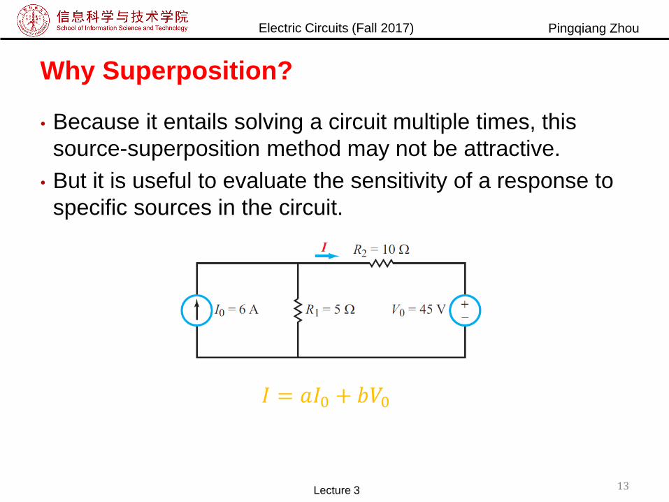
Why Superposition?
• Because it entails solving a circuit multiple times, this
source-superposition method may not be attractive.
• But it is useful to evaluate the sensitivity of a response to
specific sources in the circuit.
13Lecture 3
𝐼 = 𝑎𝐼0 + 𝑏𝑉0
Electric Circuits (Fall 2017) Pingqiang Zhou
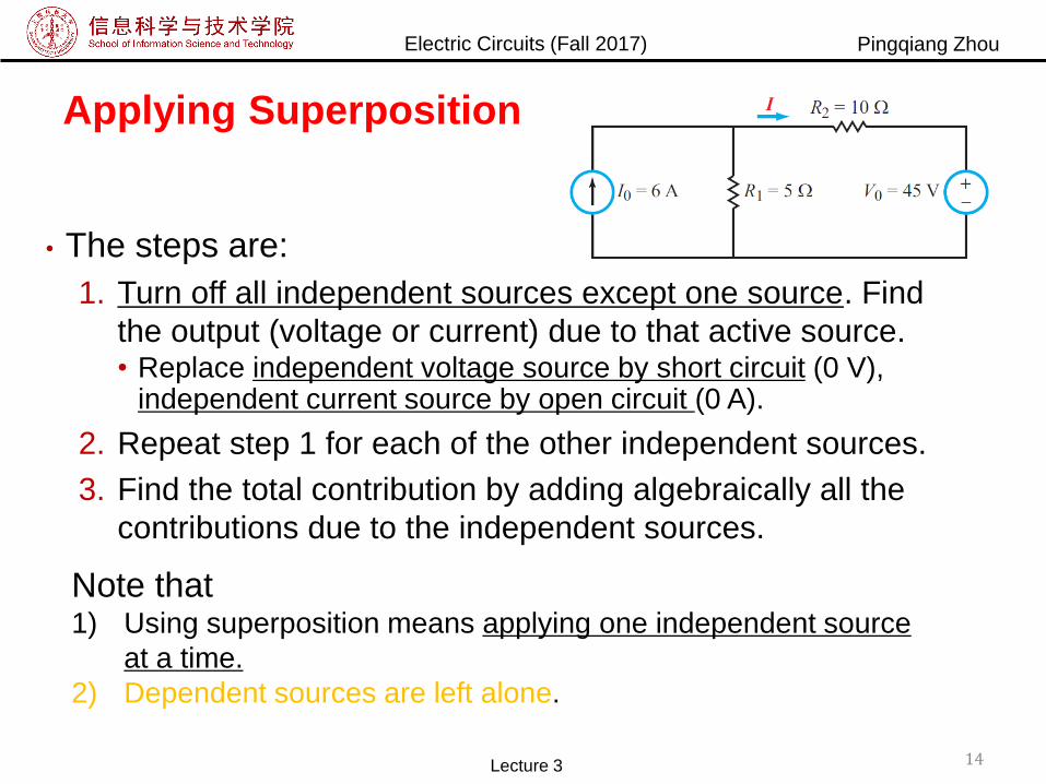
Applying Superposition
• The steps are:
1. Turn off all independent sources except one source. Find
the output (voltage or current) due to that active source.• Replace independent voltage source by short circuit (0 V),
independent current source by open circuit (0 A).
2. Repeat step 1 for each of the other independent sources.
3. Find the total contribution by adding algebraically all the
contributions due to the independent sources.
Lecture 3 14
Note that1) Using superposition means applying one independent source
at a time.
2) Dependent sources are left alone.

Electric Circuits (Fall 2017) Pingqiang Zhou
Open Circuit and Short Circuit
• Open circuit
i=0, i.e., cut off the branch
• Short circuit
v=0, i.e., replace the element by wire
• Turn off an independent voltage source means
V=0
Replace by wire
Short circuit
• Turn off an independent current source means
i=0
Cut off the branch
open circuitLecture 3 15
Electric Circuits (Fall 2017) Pingqiang Zhou
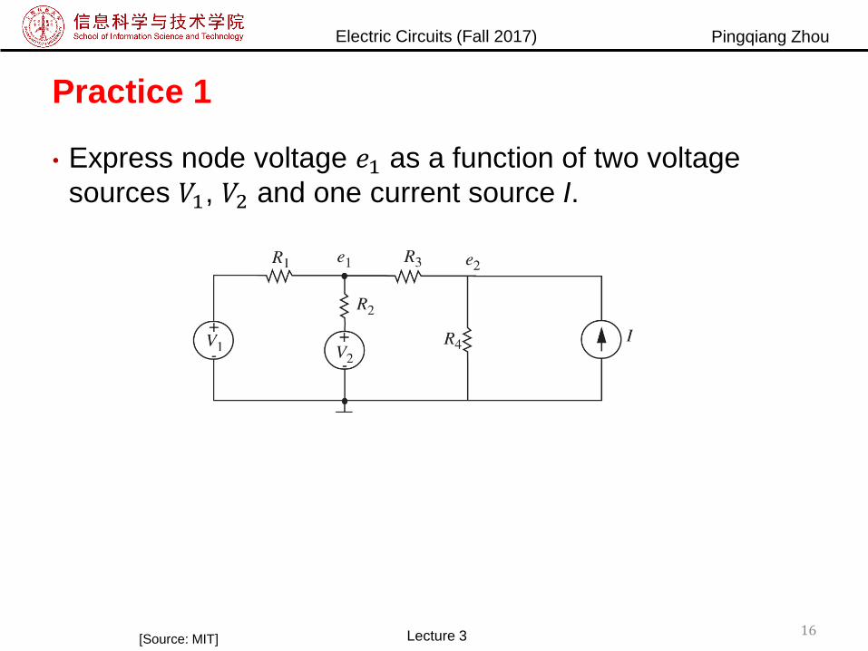
Practice 1
• Express node voltage 𝑒1 as a function of two voltage
sources 𝑉1, 𝑉2 and one current source I.
16Lecture 3[Source: MIT]
Electric Circuits (Fall 2017) Pingqiang Zhou
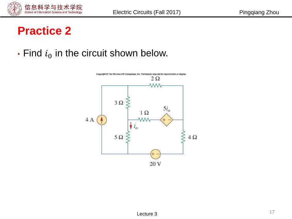
Practice 2
• Find 𝑖0 in the circuit shown below.
17Lecture 3
Electric Circuits (Fall 2017) Pingqiang Zhou
Outline
• Linearity property
• Superposition
• Thevenin’s theorem
• Source transformation
• Norton’s theorem
Lecture 3 18
Electric Circuits (Fall 2017) Pingqiang Zhou
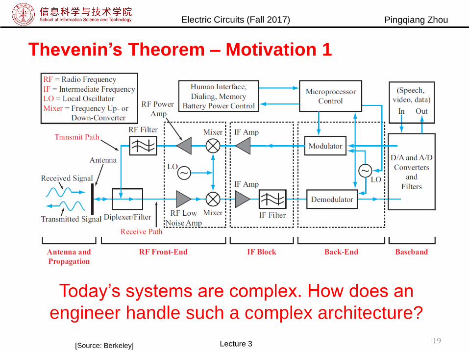
Thevenin’s Theorem – Motivation 1
Today’s systems are complex. How does an
engineer handle such a complex architecture?
[Source: Berkeley] Lecture 3 19
Electric Circuits (Fall 2017) Pingqiang Zhou
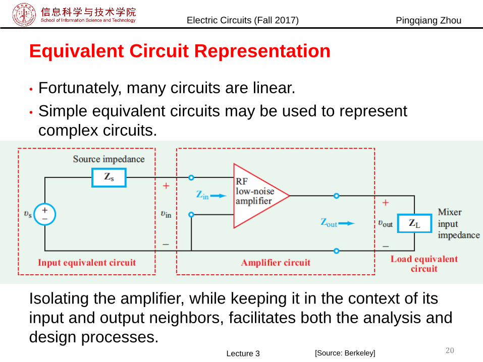
Equivalent Circuit Representation
• Fortunately, many circuits are linear.
• Simple equivalent circuits may be used to represent
complex circuits.
Isolating the amplifier, while keeping it in the context of its
input and output neighbors, facilitates both the analysis and
design processes.Lecture 3 20[Source: Berkeley]

Electric Circuits (Fall 2017) Pingqiang Zhou
Extension 3
• Q7: If 𝑅2 = 1Ω, 𝐼 =?
• Q8: What if 𝑅2 = 5Ω?
21Lecture 3
Electric Circuits (Fall 2017) Pingqiang Zhou
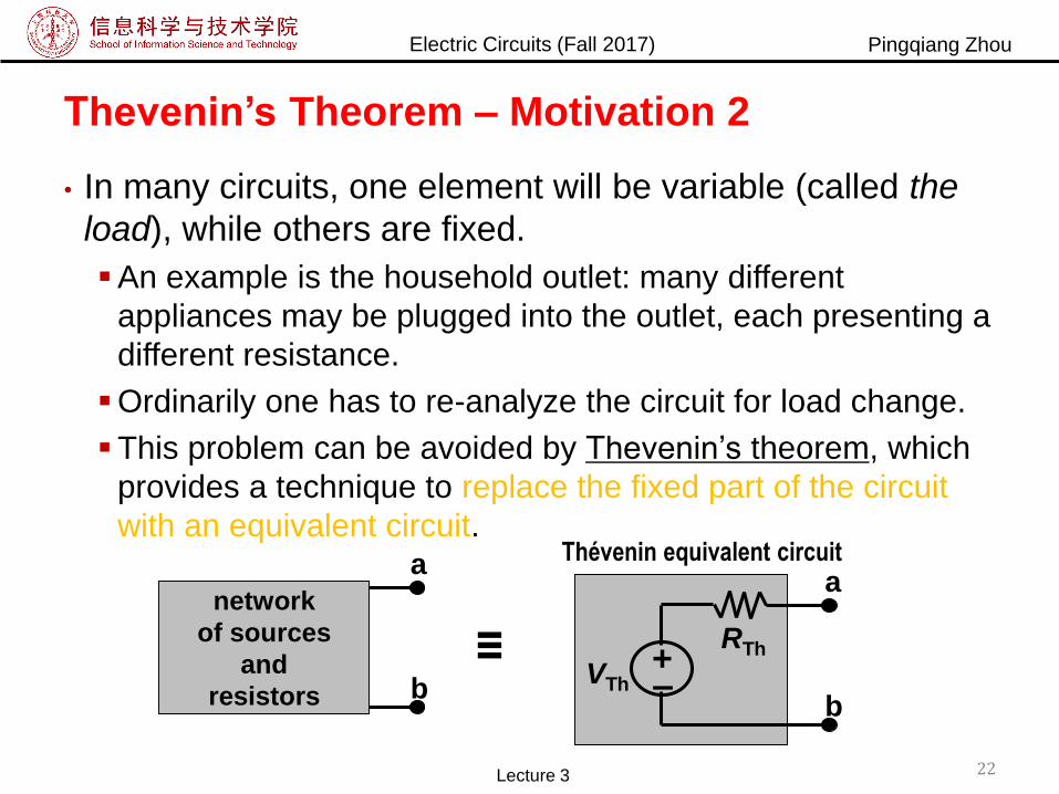
Thevenin’s Theorem – Motivation 2
• In many circuits, one element will be variable (called the
load), while others are fixed.
An example is the household outlet: many different
appliances may be plugged into the outlet, each presenting a
different resistance.
Ordinarily one has to re-analyze the circuit for load change.
This problem can be avoided by Thevenin’s theorem, which
provides a technique to replace the fixed part of the circuit
with an equivalent circuit.
network
of sources
and
resistors
≡
–+
VTh
RTh
a
b
a
b
Thé venin equivalent circuit
Lecture 3 22
Electric Circuits (Fall 2017) Pingqiang Zhou
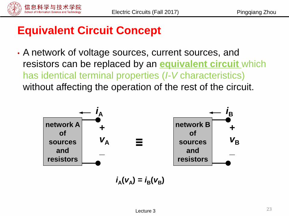
Equivalent Circuit Concept
• A network of voltage sources, current sources, and
resistors can be replaced by an equivalent circuit which
has identical terminal properties (I-V characteristics)
without affecting the operation of the rest of the circuit.
23Lecture 3
+
vA
_
network A
of
sources
and
resistors
iA
≡
+
vB
_
network B
of
sources
and
resistors
iB
iA(vA) = iB(vB)
Electric Circuits (Fall 2017) Pingqiang Zhou
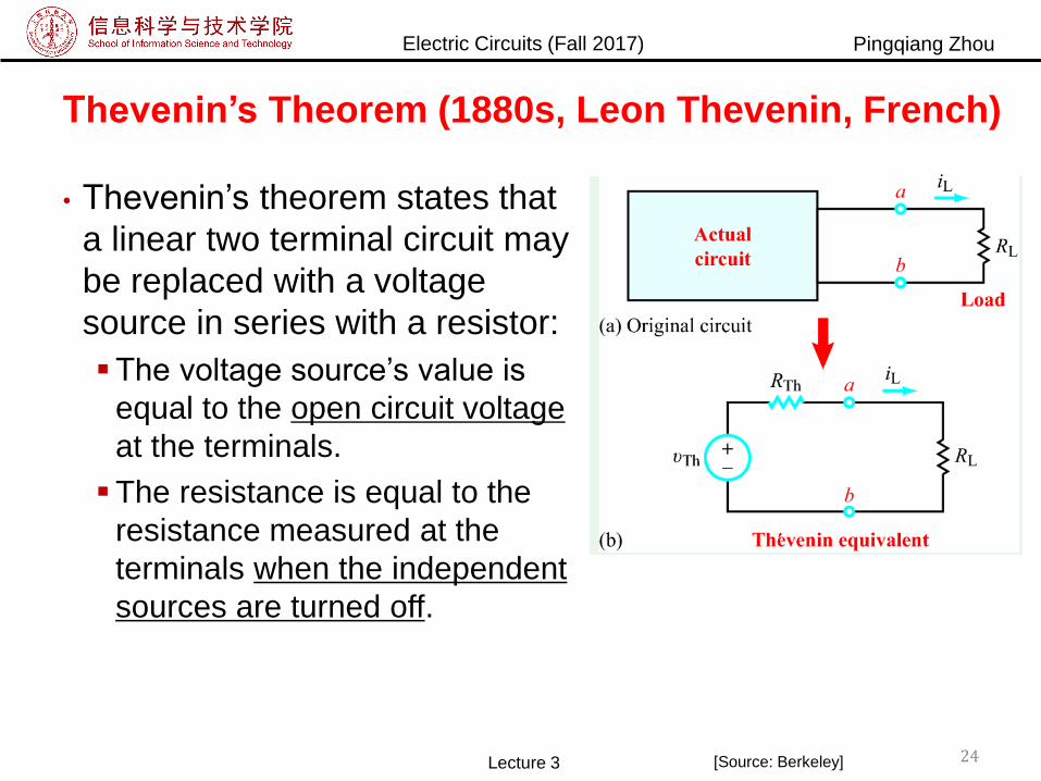
Thevenin’s Theorem (1880s, Leon Thevenin, French)
• Thevenin’s theorem states that
a linear two terminal circuit may
be replaced with a voltage
source in series with a resistor:
The voltage source’s value is
equal to the open circuit voltage
at the terminals.
The resistance is equal to the
resistance measured at the
terminals when the independent
sources are turned off.
Lecture 3 24[Source: Berkeley]
Electric Circuits (Fall 2017) Pingqiang Zhou
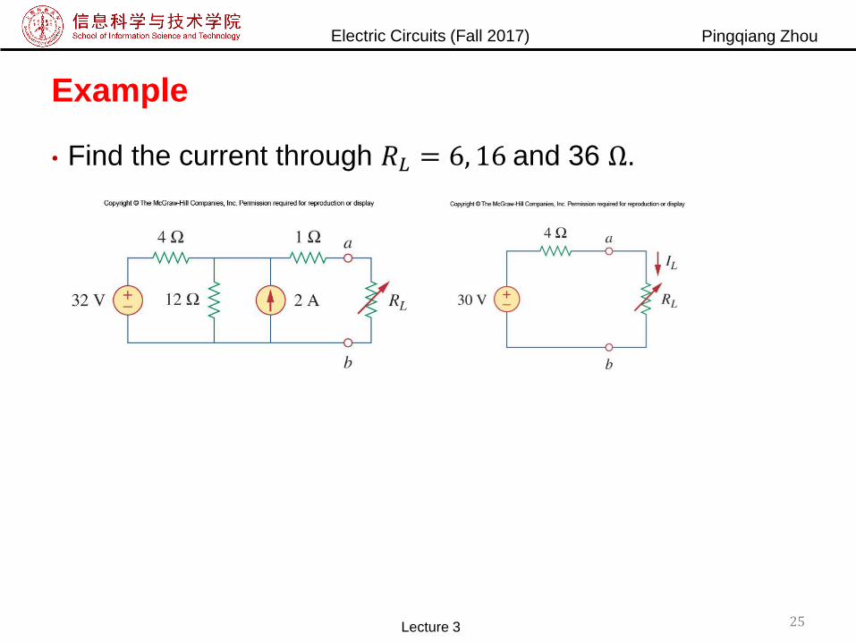
Example
• Find the current through 𝑅𝐿 = 6, 16 and 36 Ω.
25Lecture 3
Electric Circuits (Fall 2017) Pingqiang Zhou
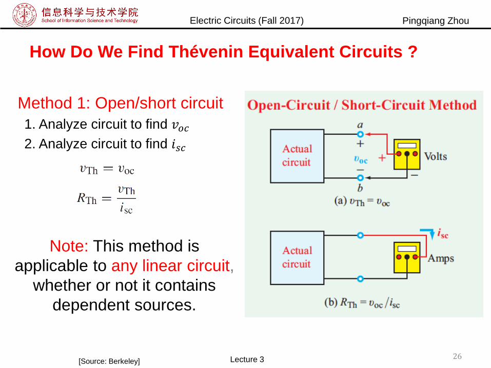
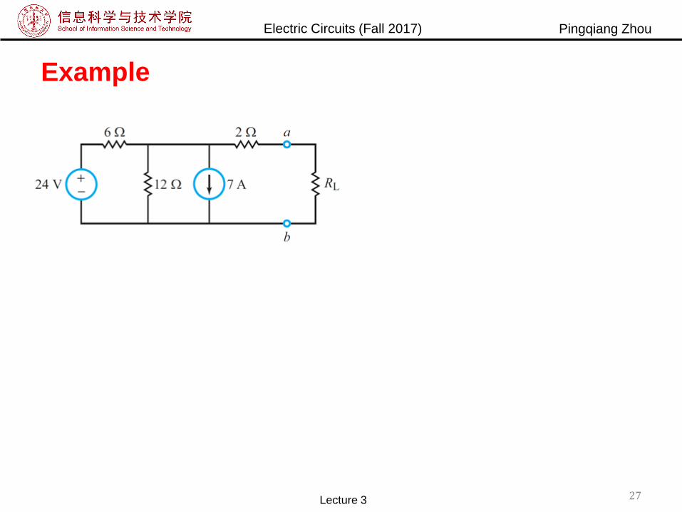
How Do We Find Thévenin Equivalent Circuits ?
Method 1: Open/short circuit
1. Analyze circuit to find 𝑣𝑜𝑐2. Analyze circuit to find 𝑖𝑠𝑐
Note: This method is
applicable to any linear circuit,
whether or not it contains
dependent sources.
[Source: Berkeley] Lecture 3 26
Electric Circuits (Fall 2017) Pingqiang Zhou
Example
Lecture 3 27

Electric Circuits (Fall 2017) Pingqiang Zhou
How Do We Find Thévenin Equivalent Circuits?
Method 2: Equivalent Resistance
1. Analyze circuit to find 𝑣𝑜𝑐
Note: This method does not
apply to circuits that contain
dependent sources.
2. Deactivate all independent sources
by replacing voltage sources with
short circuits and current sources
with open circuits.
3. Simplify circuit to find equivalent
resistance.
[Source: Berkeley] Lecture 3 28
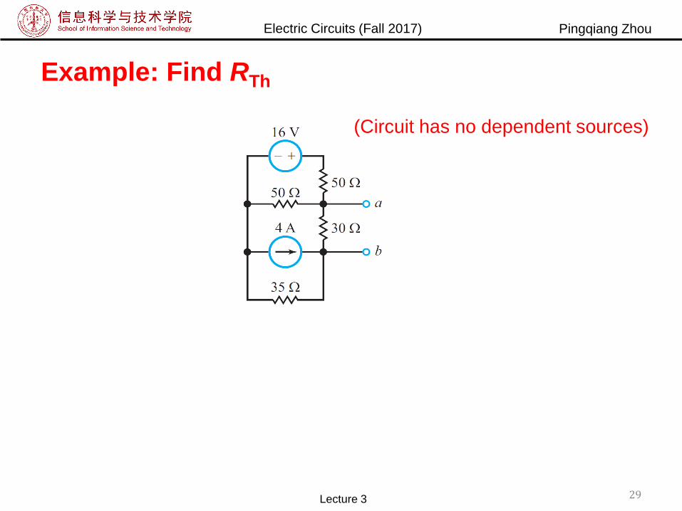
Electric Circuits (Fall 2017) Pingqiang Zhou
Example: Find RTh
(Circuit has no dependent sources)
Lecture 3 29

Electric Circuits (Fall 2017) Pingqiang Zhou
Practice
30Lecture 3

Electric Circuits (Fall 2017) Pingqiang Zhou
How Do We Find Thévenin Equivalent Circuits?
Method 3:
[Source: Berkeley] Lecture 3 31
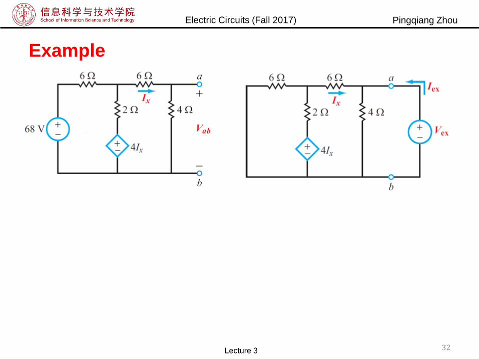
Electric Circuits (Fall 2017) Pingqiang Zhou
Example
Lecture 3 32
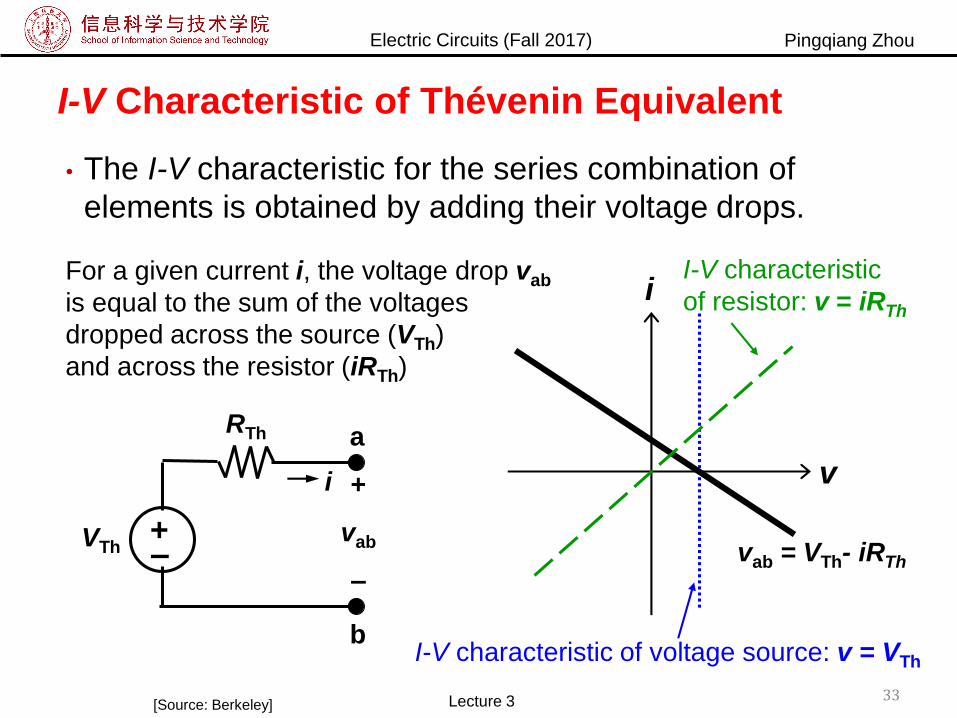
Electric Circuits (Fall 2017) Pingqiang Zhou
I-V Characteristic of Thévenin Equivalent
• The I-V characteristic for the series combination of
elements is obtained by adding their voltage drops.
–+
VTh
RTh a
b
i +
vab
–
For a given current i, the voltage drop vab
is equal to the sum of the voltages
dropped across the source (VTh)
and across the resistor (iRTh)
i
I-V characteristic of voltage source: v = VTh
vab = VTh- iRTh
v
I-V characteristic
of resistor: v = iRTh
Lecture 3 33[Source: Berkeley]
Electric Circuits (Fall 2017) Pingqiang Zhou
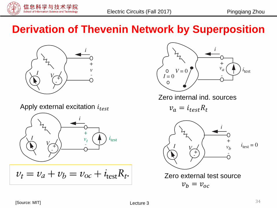
Derivation of Thevenin Network by Superposition
34Lecture 3[Source: MIT]
Apply external excitation 𝑖𝑡𝑒𝑠𝑡
Zero internal ind. sources
Zero external test source
𝑣𝑎 = 𝑖𝑡𝑒𝑠𝑡𝑅𝑡
𝑣𝑏 = 𝑣𝑜𝑐
Electric Circuits (Fall 2017) Pingqiang Zhou
Outline
• Linearity property
• Superposition
• Thevenin’s theorem
• Source transformation
• Norton’s theorem
Lecture 3 35
Electric Circuits (Fall 2017) Pingqiang Zhou
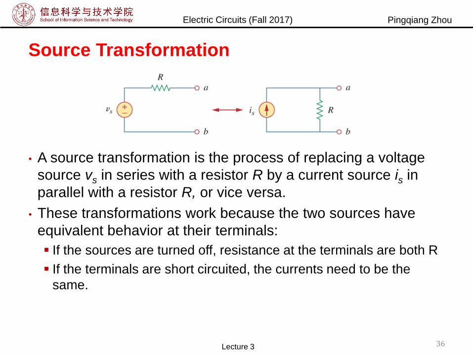
Source Transformation
• A source transformation is the process of replacing a voltage
source vs in series with a resistor R by a current source is in
parallel with a resistor R, or vice versa.
• These transformations work because the two sources have
equivalent behavior at their terminals:
If the sources are turned off, resistance at the terminals are both R
If the terminals are short circuited, the currents need to be the
same.
Lecture 3 36
Electric Circuits (Fall 2017) Pingqiang Zhou
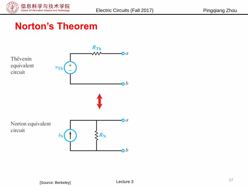
Norton’s Theorem
[Source: Berkeley] Lecture 3 37
Electric Circuits (Fall 2017) Pingqiang Zhou
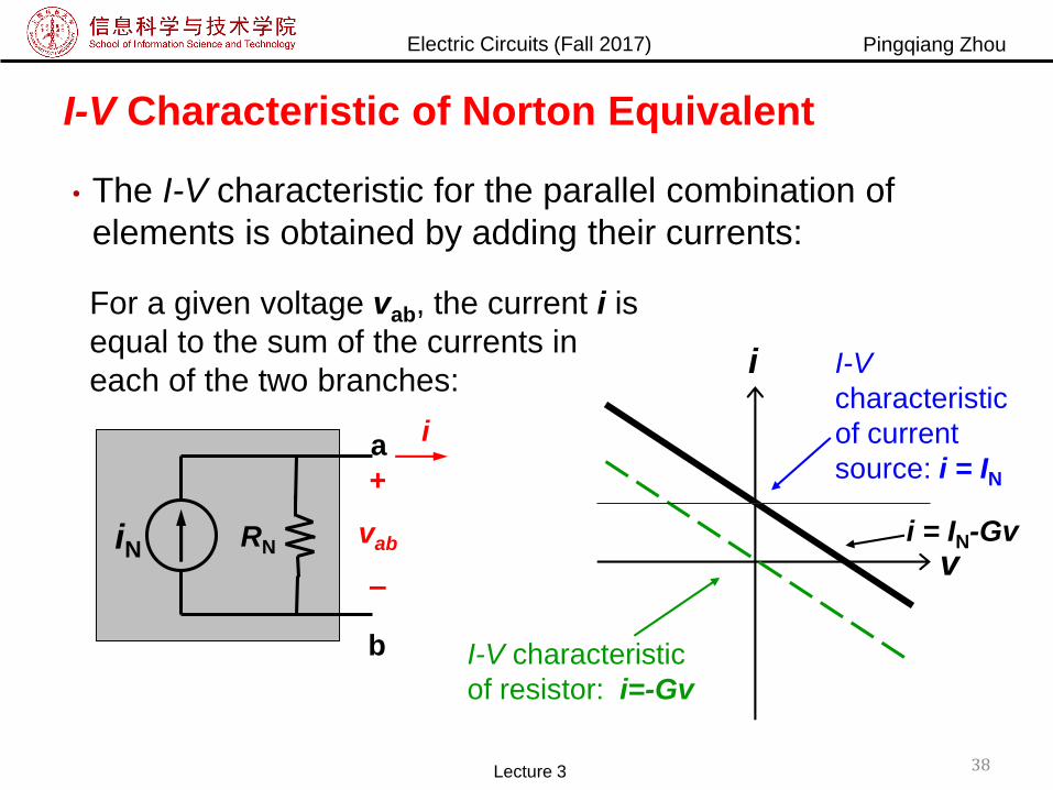
I-V Characteristic of Norton Equivalent
• The I-V characteristic for the parallel combination of
elements is obtained by adding their currents:
i I-V
characteristic
of current
source: i = IN
I-V characteristic
of resistor: i=-Gv
For a given voltage vab, the current i is
equal to the sum of the currents in
each of the two branches:
vi = IN-Gv
i
+
vab
–
iN
b
RN
a
Lecture 3 38

Electric Circuits (Fall 2017) Pingqiang Zhou
Derivation of Norton Network
39Lecture 3[Source: MIT]

Electric Circuits (Fall 2017) Pingqiang Zhou
Summary
• Superposition Voltage off SC
Current off OC
• Thevenin and Norton Equivalent Circuits Solve for OC voltage
Solve for SC current
Lecture 3 40
ThN
Th
VI
R
RNIN
a
b
–+
VTh
RTh a
b
ThN RR

Electric Circuits (Fall 2017) Pingqiang Zhou
New Content for the Discussion Session
• Max Power Transfer
• Tellegen’s Theorem?
41Lecture 3
–+
VTh
RTh
RL
iL+
vL
–
https://en.wikipedia.org/wiki/Tellegen%2
7s_theorem
Electric Circuits (Fall 2017) Pingqiang Zhou
42Lecture 3
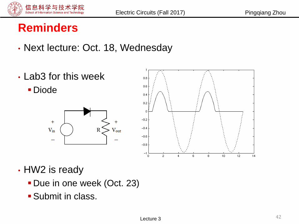
Reminders
• Next lecture: Oct. 18, Wednesday
• Lab3 for this week
Diode
• HW2 is ready
Due in one week (Oct. 23)
Submit in class.


![algebraic topologyamathew/ATnotes.pdf · 2015-09-03 · the theorem 55 Lecture 17 [Section] 10/4 ... approximation theorem 58 x4 Lefschetz xed point theorem 59 Lecture 19 10/8 x1](https://img.pdfslide.us/doc/110x75/5ea492f5a0779303944d67a4/algebraic-topology-amathewatnotespdf-2015-09-03-the-theorem-55-lecture-17.jpg)