Embed Size (px)
Citation preview
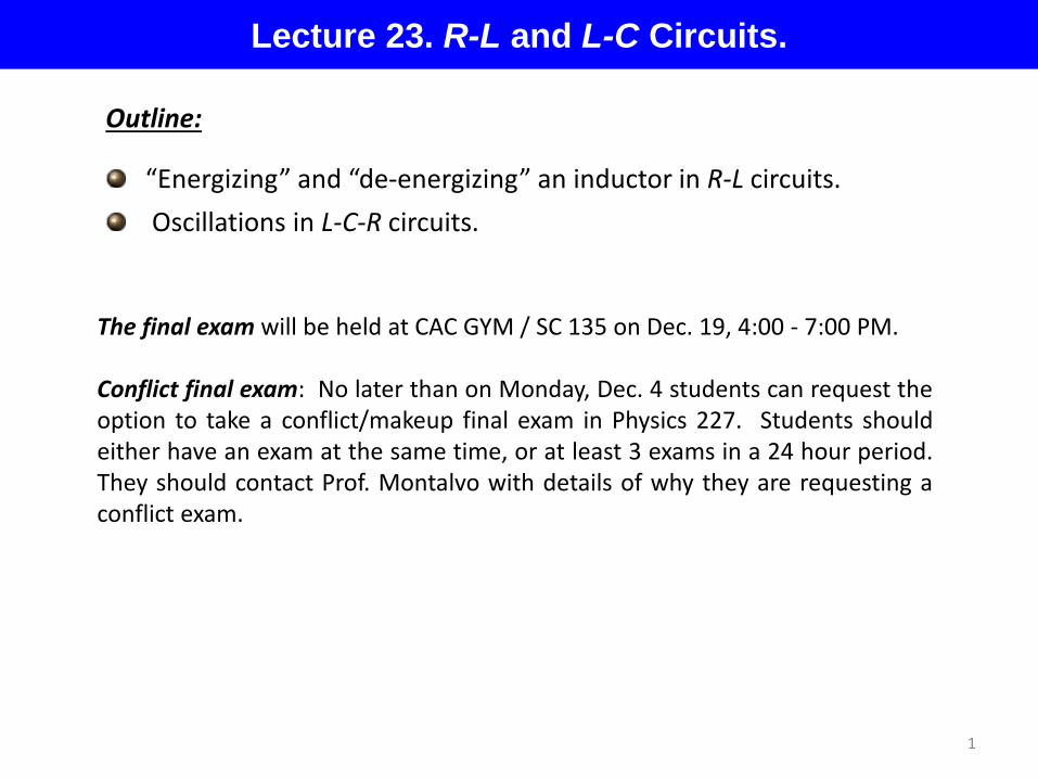
Lecture 23. R-L and L-C Circuits.
Outline:
“Energizing” and “de-energizing” an inductor in R-L circuits. Oscillations in L-C-R circuits.
1
The final exam will be held at CAC GYM / SC 135 on Dec. 19, 4:00 - 7:00 PM. Conflict final exam: No later than on Monday, Dec. 4 students can request the option to take a conflict/makeup final exam in Physics 227. Students should either have an exam at the same time, or at least 3 exams in a 24 hour period. They should contact Prof. Montalvo with details of why they are requesting a conflict exam.

2
#01B7289E 33 #07005C5B 34 #0B9BDB4B 59 #0BA555FB 30 #0BE96A88 41 #0CC5E42D 57 #0D4B480E 66 #0D4C3C7D 44 #0E774C35 51 #39315B53 25 #418309CB 21 #418675B2 32 #419A4299 33 #429D4B94 23 #42AE876B 27 #4551ECF8 21 #48484B4B 26 #491FA9FF 40 #8E7CBA48 54 #9AD32D64 30
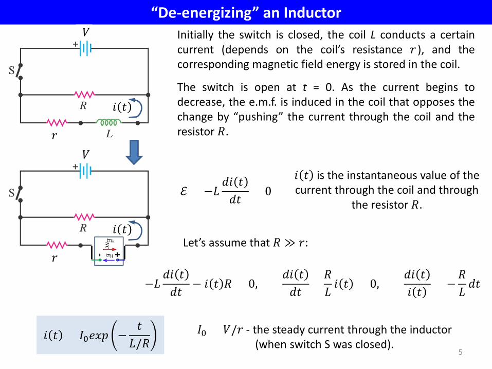
“De-energizing” an Inductor
5
𝑟
Initially the switch is closed, the coil L conducts a certain current (depends on the coil’s resistance 𝑟 ), and the corresponding magnetic field energy is stored in the coil.
The switch is open at t = 0. As the current begins to decrease, the e.m.f. is induced in the coil that opposes the change by “pushing” the current through the coil and the resistor 𝑅.
ℰ = −𝐿𝑑𝑑 𝑡𝑑𝑡 > 0
𝑑 𝑡 is the instantaneous value of the current through the coil and through
the resistor 𝑅.
𝑑 𝑡
𝑉
𝐼0 = 𝑉/𝑟 - the steady current through the inductor (when switch S was closed).
Let’s assume that 𝑅 ≫ 𝑟:
𝑑 𝑡 = 𝐼0𝑣𝑒𝑒 −𝑡
𝐿/𝑅
−𝐿𝑑𝑑 𝑡𝑑𝑡 − 𝑑 𝑡 𝑅 = 0,
𝑑𝑑 𝑡𝑑𝑡 +
𝑅𝐿 𝑑 𝑡 = 0,
𝑑𝑑 𝑡𝑑 𝑡 = −
𝑅𝐿 𝑑𝑡

“De-energizing” an Inductor
6
𝑟
𝑑 𝑡
𝑑 𝑡 = 𝐼0𝑣𝑒𝑒 −𝑡
𝐿/𝑅
𝐼0
𝑡 = 𝜏
𝜏 =𝐿𝑅
- the time constant of the circuit which consists of an inductor 𝐿 and resistor 𝑅 .
Let’s check that 𝐿/𝑅 has units of time:
𝐿𝑅 =
𝐿𝐼2
𝑅𝐼2 →𝐽𝐽/𝑠 = 𝑠
𝑉
𝐼0 = 𝑉/𝑟 - the steady current through the inductor (when switch S was closed).
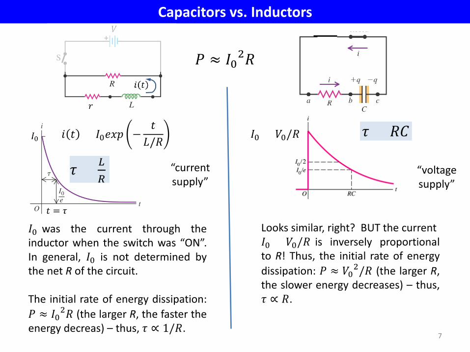
Capacitors vs. Inductors
7
𝐼0 was the current through the inductor when the switch was “ON”. In general, 𝐼0 is not determined by the net R of the circuit. The initial rate of energy dissipation: 𝑃 ≈ 𝐼02𝑅 (the larger R, the faster the energy decreas) – thus, 𝜏 ∝ 1/𝑅.
𝑑 𝑡 = 𝐼0𝑣𝑒𝑒 −𝑡
𝐿/𝑅
Looks similar, right? BUT the current 𝐼0 = 𝑉0/𝑅 is inversely proportional to R! Thus, the initial rate of energy dissipation: 𝑃 ≈ 𝑉02/𝑅 (the larger R, the slower energy decreases) – thus, 𝜏 ∝ 𝑅.
𝜏 = 𝑅𝑅 𝐼0 = 𝑉0/𝑅
“current supply”
“voltage supply”
𝑃 ≈ 𝐼02𝑅
𝜏 = 𝐿𝑅
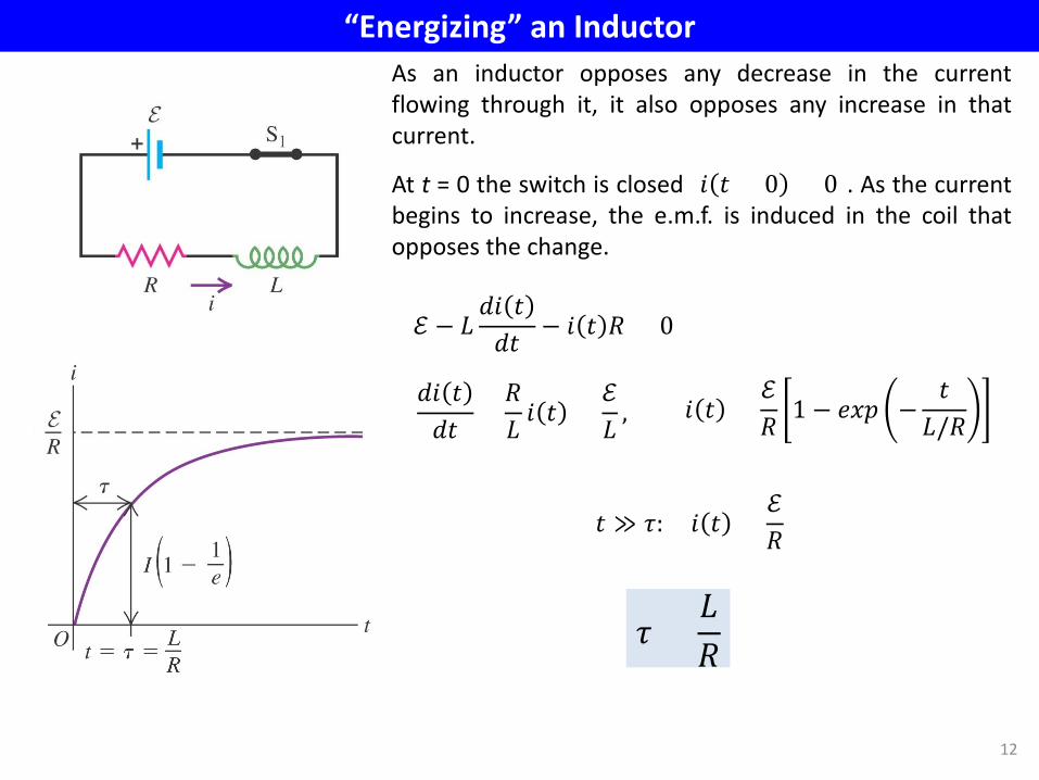
“Energizing” an Inductor
12
As an inductor opposes any decrease in the current flowing through it, it also opposes any increase in that current.
At t = 0 the switch is closed [𝑑 𝑡 = 0 = 0]. As the current begins to increase, the e.m.f. is induced in the coil that opposes the change.
ℰ − 𝐿𝑑𝑑 𝑡𝑑𝑡
− 𝑑 𝑡 𝑅 = 0
𝑑 𝑡 =ℰ𝑅 1 − 𝑣𝑒𝑒 −
𝑡𝐿/𝑅
𝑑𝑑 𝑡𝑑𝑡 +
𝑅𝐿 𝑑 𝑡 =
ℰ𝐿 ,
𝑡 ≫ 𝜏: 𝑑 𝑡 =ℰ𝑅
𝜏 =𝐿𝑅
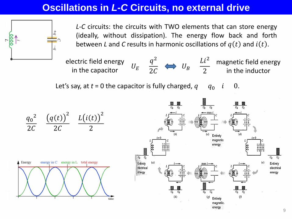
Oscillations in L-C Circuits, no external drive
19
L-C circuits: the circuits with TWO elements that can store energy (ideally, without dissipation). The energy flow back and forth between L and C results in harmonic oscillations of 𝑞 𝑡 and 𝑑 𝑡 .
𝑈𝐸 =𝑞2
2𝑅 𝑈𝐵 =𝐿𝑑2
2 electric field energy
in the capacitor magnetic field energy
in the inductor
Let’s say, at t = 0 the capacitor is fully charged, 𝑞 = 𝑞0 𝑑 = 0.
𝑞02
2𝑅 =𝑞 𝑡 2
2𝑅 +𝐿 𝑑 𝑡 2
2
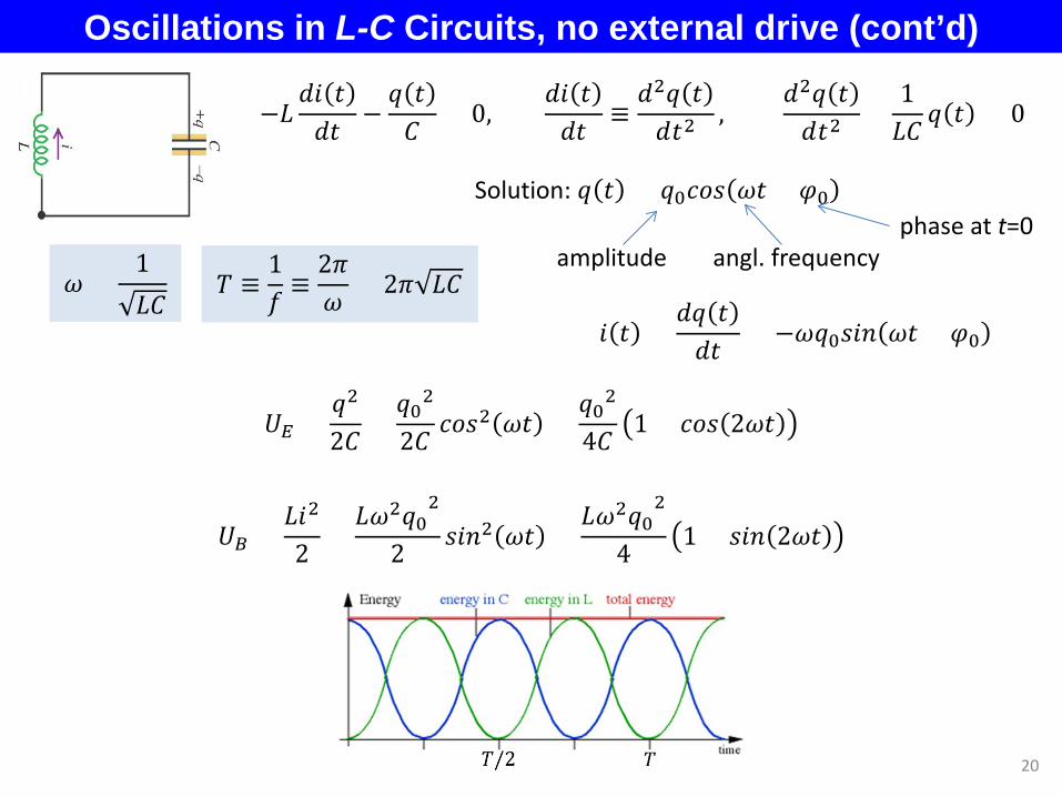
Oscillations in L-C Circuits, no external drive (cont’d)
20
−𝐿𝑑𝑑 𝑡𝑑𝑡
−𝑞 𝑡𝑅
= 0,𝑑𝑑 𝑡𝑑𝑡
≡𝑑2𝑞 𝑡𝑑𝑡2
, 𝑑2𝑞 𝑡𝑑𝑡2
+1𝐿𝑅
𝑞 𝑡 = 0
Solution: 𝑞 𝑡 = 𝑞0𝑐𝑣𝑠 𝜔𝑡 + 𝜑0
amplitude angl. frequency phase at t=0
𝜔 =1𝐿𝑅
𝑇 ≡1𝑓≡2𝜋𝜔
= 2𝜋 𝐿𝑅
𝑈𝐸 =𝑞2
2𝑅 =𝑞02
2𝑅 𝑐𝑣𝑠2 𝜔𝑡 =𝑞02
4𝑅 1 + 𝑐𝑣𝑠 2𝜔𝑡
𝑑 𝑡 =𝑑𝑞 𝑡𝑑𝑡
= −𝜔𝑞0𝑠𝑑𝑠 𝜔𝑡 + 𝜑0
𝑈𝐵 =𝐿𝑑2
2 =𝐿𝜔2𝑞0
2
2 𝑠𝑑𝑠2 𝜔𝑡 =𝐿𝜔2𝑞0
2
4 1 + 𝑠𝑑𝑠 2𝜔𝑡
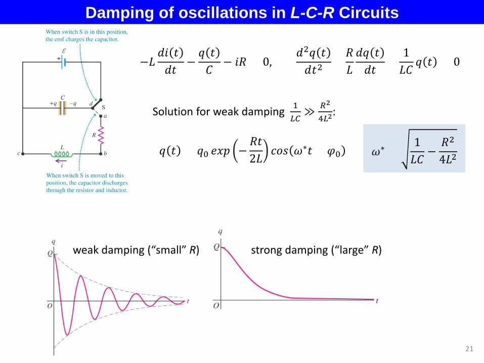
Damping of oscillations in L-C-R Circuits
21
weak damping (“small” R) strong damping (“large” R)
−𝐿𝑑𝑑 𝑡𝑑𝑡 −
𝑞 𝑡𝑅 − 𝑑𝑅 = 0,
𝑑2𝑞 𝑡𝑑𝑡2 +
𝑅𝐿𝑑𝑞 𝑡𝑑𝑡 +
1𝐿𝑅
𝑞 𝑡 = 0
Solution for weak damping 1𝐿𝐿≫ 𝑅2
4𝐿2:
𝑞 𝑡 = 𝑞0 𝑣𝑒𝑒 −𝑅𝑡2𝐿
𝑐𝑣𝑠 𝜔∗𝑡 + 𝜑0 𝜔∗ =1𝐿𝑅
−𝑅2
4𝐿2

24
Next time: Lecture 24. Impedance of AC circuits, §§ 31.3 - 6
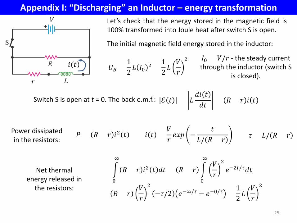
Appendix I: “Discharging” an Inductor – energy transformation
25
𝑟
𝑑 𝑡
Let’s check that the energy stored in the magnetic field is 100% transformed into Joule heat after switch S is open.
The initial magnetic field energy stored in the inductor:
𝑈𝐵 =12𝐿 𝐼0 2 =
12𝐿𝑉𝑟
2
𝐼0 = 𝑉/𝑟 - the steady current through the inductor (switch S
is closed).
𝑉
Power dissipated in the resistors:
𝑃 = 𝑅 + 𝑟 𝑑2 𝑡
Net thermal energy released in
the resistors:
� 𝑅 + 𝑟 𝑑2 𝑡 𝑑𝑡∞
0
= 𝑅 + 𝑟 �𝑉𝑟
2𝑣−2𝑡/𝜏𝑑𝑡
∞
0
= 𝑅 + 𝑟𝑉𝑟
2−𝜏/2 𝑣−∞/𝜏 − 𝑣−0/𝜏 =
12 𝐿
𝑉𝑟
2
ℰ 𝑡 = 𝐿𝑑𝑑 𝑡𝑑𝑡 = 𝑅 + 𝑟 𝑑 𝑡 Switch S is open at t = 0. The back e.m.f.:
𝑑 𝑡 =𝑉𝑟 𝑣𝑒𝑒 −
𝑡𝐿/ 𝑅 + 𝑟 𝜏 = 𝐿/ 𝑅 + 𝑟

A. never
B. always
C. only if R+r is sufficiently small
D. only if R+r is sufficiently large
Appendix II: Example
26
𝑟
Initially the switch is closed, the coil L conducts a certain current, and the corresponding magnetic field energy is stored in the coil. The switch is open at t = 0, and the back e.m.f. ℰ is induced in the coil. Can ℰ 𝑡 = 0 be greater than V?
𝑑 𝑡
𝑉
ℰ = −𝐿𝑑𝑑 𝑡𝑑𝑡
= −𝐿𝑑𝑑𝑡 𝑑0𝑣𝑒𝑒 −
𝑡𝐿/ 𝑅 + 𝑟
= 𝐿𝑑0𝑅 + 𝑟𝐿 𝑣𝑒𝑒 −
𝑡𝐿/ 𝑅 + 𝑟
=𝑉𝑟 𝑅 + 𝑟 𝑣𝑒𝑒 −
𝑡𝐿/ 𝑅 + 𝑟
𝑑0 = 𝑉/𝑟


![L 26 Electricity and Magnetism [3] Electric circuits Electric circuits what conducts electricity what conducts electricity what doesn’t conduct electricity](https://img.pdfslide.us/doc/110x75/56649dc55503460f94ab893c/l-26-electricity-and-magnetism-3-electric-circuits-electric-circuits-what.jpg)

![1 L 27 Electricity and Magnetism [4] simple electrical circuits – direct current DC simple electrical circuits – direct current DC Alternating current](https://img.pdfslide.us/doc/110x75/56649dbc5503460f94aad840/1-l-27-electricity-and-magnetism-4-simple-electrical-circuits-direct.jpg)