Embed Size (px)
DESCRIPTION
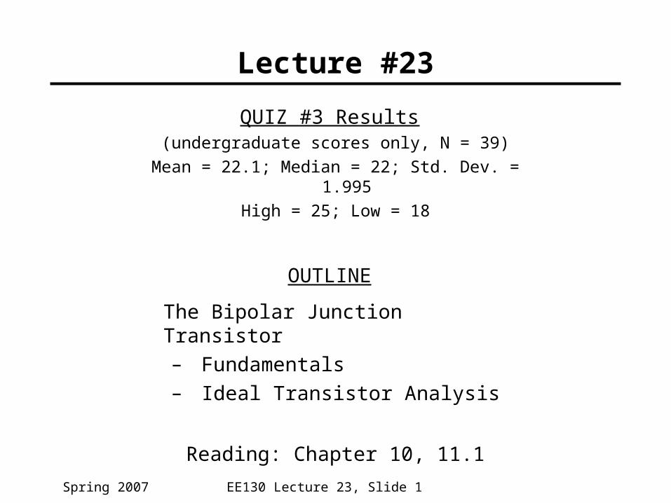
QUIZ #3 Results (undergraduate scores only, N = 39) Mean = 22.1; Median = 22; Std. Dev. = 1.995 High = 25; Low = 18 OUTLINE The Bipolar Junction Transistor Fundamentals Ideal Transistor Analysis Reading: Chapter 10, 11.1. Lecture #23. Base Current Components (Active Bias). - PowerPoint PPT Presentation
Citation preview
EE130 Lecture 23, Slide 1Spring 2007
Lecture #23
QUIZ #3 Results (undergraduate scores only, N = 39)
Mean = 22.1; Median = 22; Std. Dev. = 1.995
High = 25; Low = 18
OUTLINE
The Bipolar Junction Transistor– Fundamentals– Ideal Transistor Analysis
Reading: Chapter 10, 11.1
EE130 Lecture 23, Slide 2Spring 2007
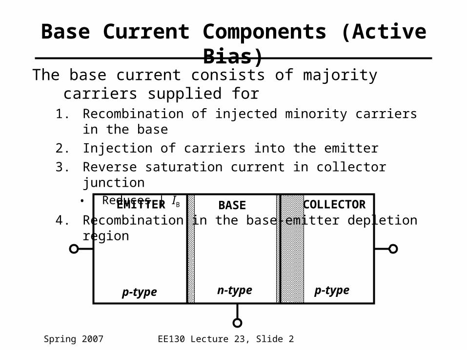
The base current consists of majority carriers supplied for1. Recombination of injected minority carriers in the base
2. Injection of carriers into the emitter
3. Reverse saturation current in collector junction• Reduces | IB |
4. Recombination in the base-emitter depletion region
Base Current Components (Active Bias)
EMITTER BASE COLLECTOR
p-type n-type p-type

EE130 Lecture 23, Slide 3Spring 2007
Circuit Configurations
Output Characteristics for Common-Emitter Configuration
EE130 Lecture 23, Slide 4Spring 2007
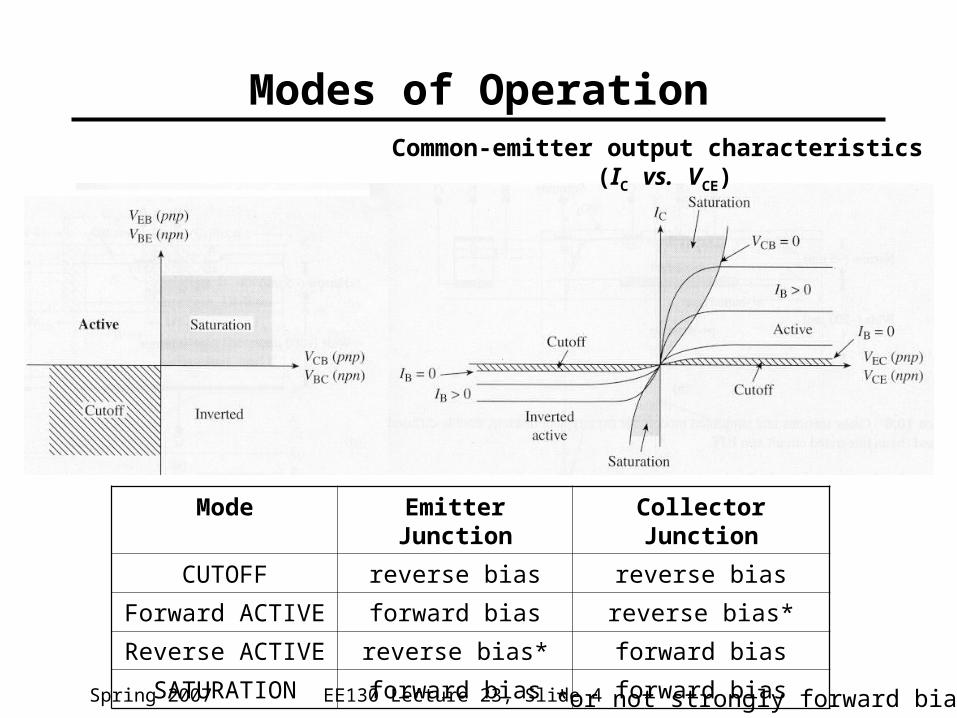
Modes of OperationCommon-emitter output characteristics
(IC vs. VCE)
Mode Emitter Junction Collector Junction
CUTOFF reverse bias reverse bias
Forward ACTIVE forward bias reverse bias*
Reverse ACTIVE reverse bias* forward bias
SATURATION forward bias forward bias
*or not strongly forward biased
EE130 Lecture 23, Slide 5Spring 2007
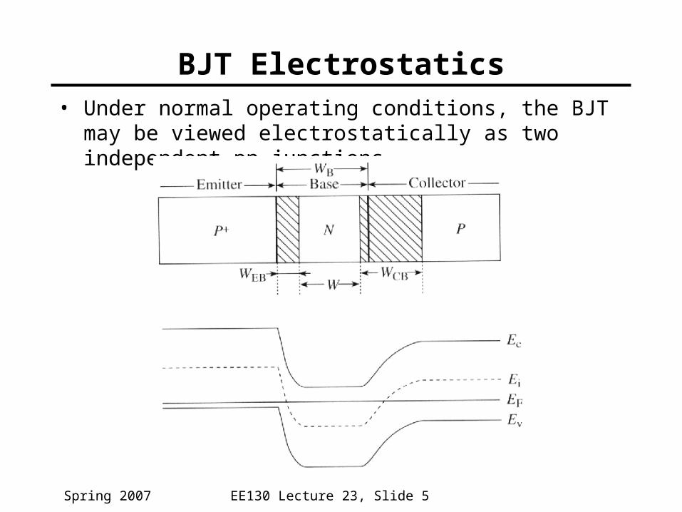
BJT Electrostatics• Under normal operating conditions, the BJT may be
viewed electrostatically as two independent pn junctions
EE130 Lecture 23, Slide 6Spring 2007
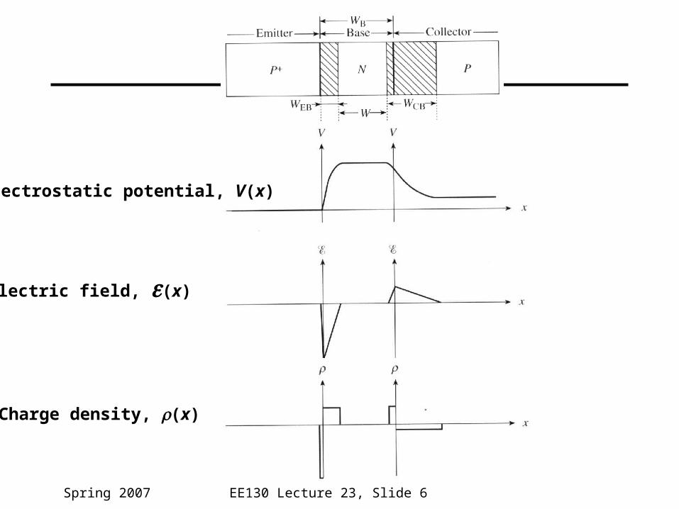
Electrostatic potential, V(x)
Electric field, (x)
Charge density, (x)
EE130 Lecture 23, Slide 7Spring 2007
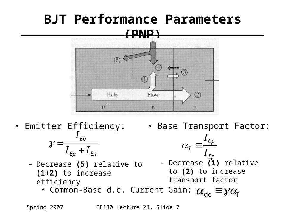
BJT Performance Parameters (PNP)
• Emitter Efficiency:
– Decrease (5) relative to (1+2) to increase efficiency
• Base Transport Factor:
– Decrease (1) relative to (2) to increase transport factor
Ep
CpT I
I
Tdc • Common-Base d.c. Current Gain:
EnEp
Ep
II
I

EE130 Lecture 23, Slide 8Spring 2007
Collector Current (PNP)• The collector current is comprised of
• Holes injected from emitter, which do not recombine in the base (2)
• Reverse saturation current of collector junction (3)
where ICB0 is the collector current
which flows when IE = 0
0
0
0
α1α1
α
α
CEB
dc
CBB
dc
dcC
CBBCdcC
IβI
III
IIII
0α CBEdcC III
• Common-Emitter d.c. Current Gain:
dc
dc
B
Cdc I
I
1
EE130 Lecture 23, Slide 9Spring 2007
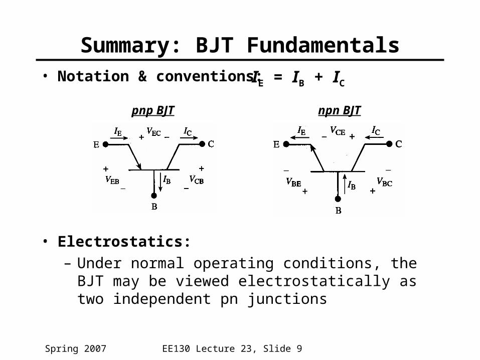
Summary: BJT Fundamentals• Notation & conventions:
• Electrostatics:– Under normal operating conditions, the BJT may
be viewed electrostatically as two independent pn junctions
IE = IB + IC
pnp BJT npn BJT
EE130 Lecture 23, Slide 10Spring 2007
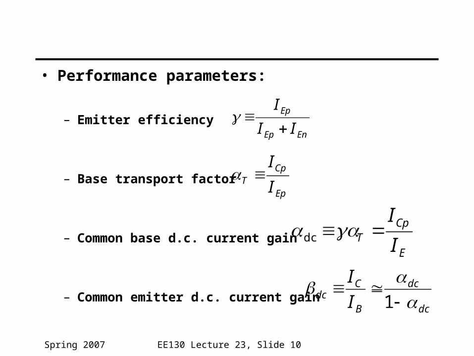
• Performance parameters:
– Emitter efficiency
– Base transport factor
– Common base d.c. current gain
– Common emitter d.c. current gain
EnEp
Ep
II
I
E
CpT I
Idc
dc
dc
B
Cdc I
I
1
Ep
CpT I
I
EE130 Lecture 23, Slide 11Spring 2007
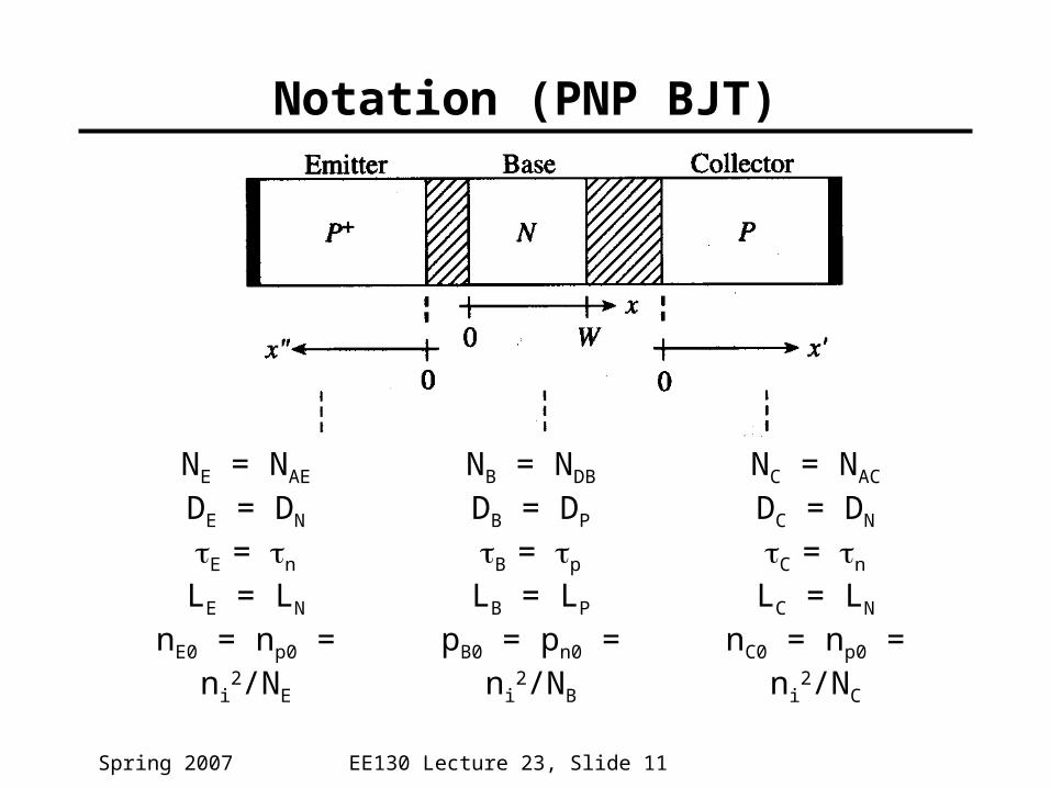
Notation (PNP BJT)
NE = NAE
DE = DN
E = n
LE = LN
nE0 = np0 = ni2/NE
NB = NDB
DB = DP
B = p
LB = LP
pB0 = pn0 = ni2/NB
NC = NAC
DC = DN
C = n
LC = LN
nC0 = np0 = ni2/NC
EE130 Lecture 23, Slide 12Spring 2007
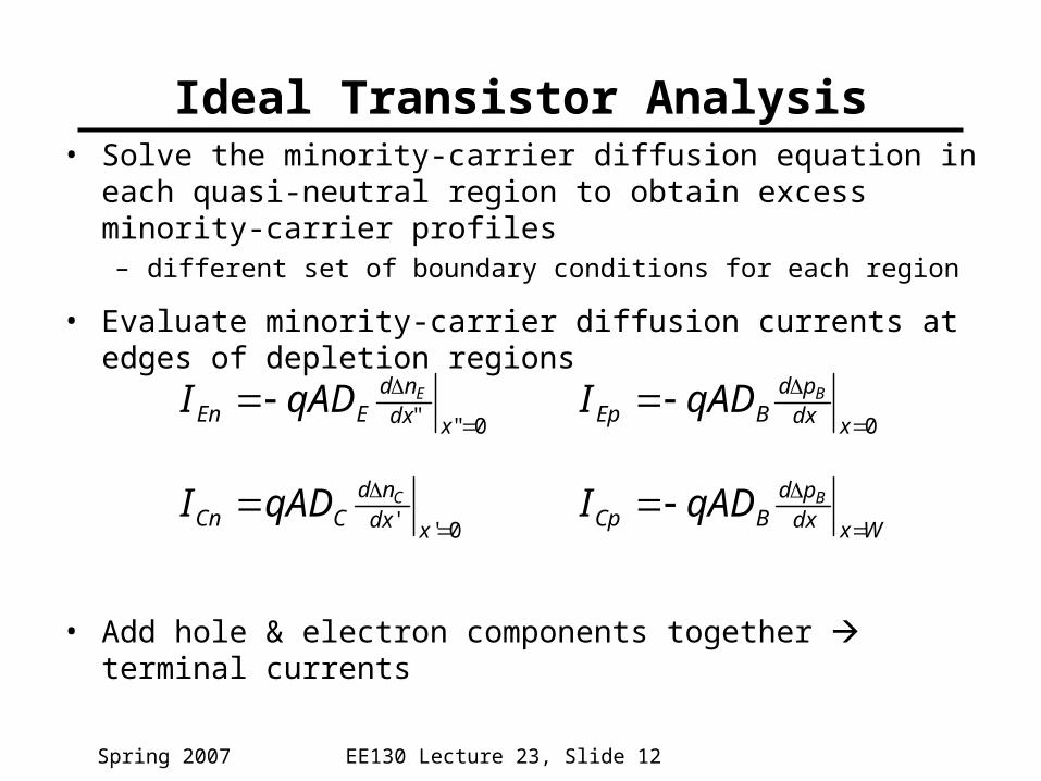
Ideal Transistor Analysis• Solve the minority-carrier diffusion equation in each quasi-neutral
region to obtain excess minority-carrier profiles– different set of boundary conditions for each region
• Evaluate minority-carrier diffusion currents at edges of depletion regions
• Add hole & electron components together terminal currents
0""
xdx
ndEEn
EqADI0
xdx
pdBEp
BqADI
Wxdxpd
BCpBqADI
0''
xdx
ndCCn
CqADI

EE130 Lecture 23, Slide 13Spring 2007
Emitter Region Formulation
• Diffusion equation:
• Boundary Conditions:
E
EE n
dx
ndED
2
2
"0
)1()0"(
0)"(/
0
kTqV
EE
E
EBenxn
xn
EE130 Lecture 23, Slide 14Spring 2007
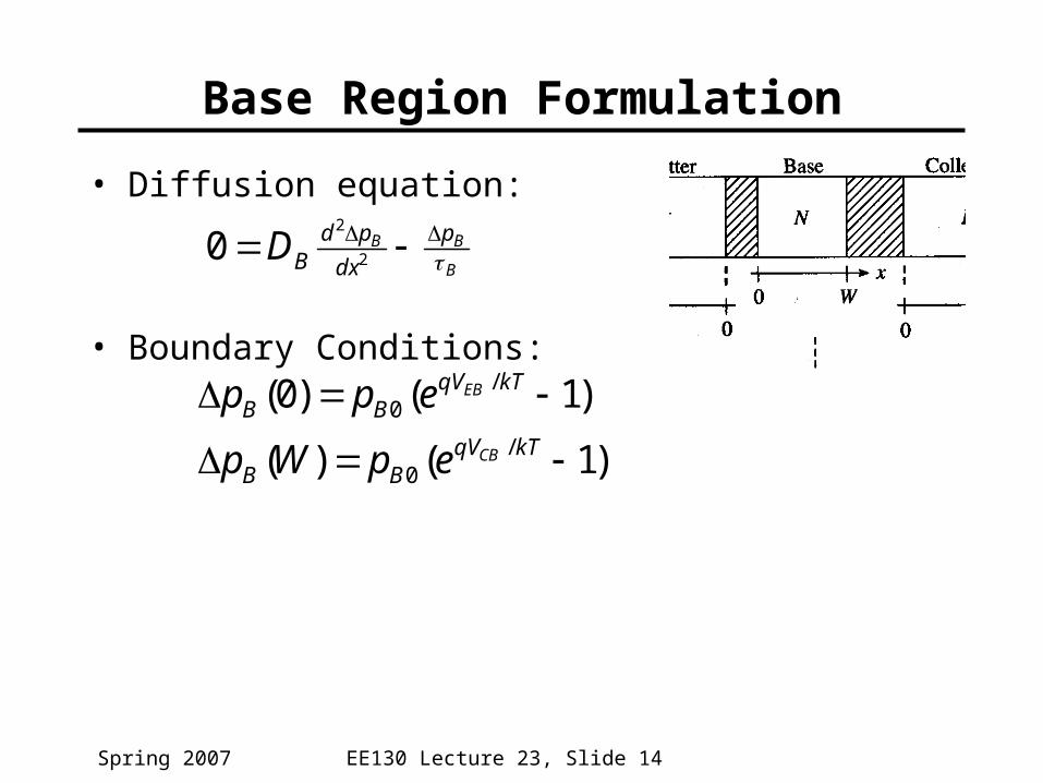
Base Region Formulation
• Diffusion equation:
• Boundary Conditions:
B
BB p
dx
pdBD
2
2
0
)1()(
)1()0(/
0
/0
kTqV
BB
kTqVBB
CB
EB
epWp
epp
EE130 Lecture 23, Slide 15Spring 2007
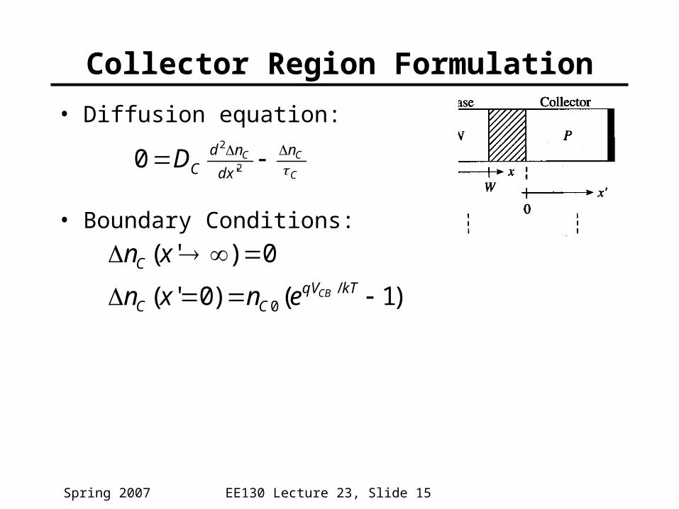
Collector Region Formulation
• Diffusion equation:
• Boundary Conditions:
C
CC n
dx
ndCD
2
2
'0
)1()0'(
0)'(/
0
kTqV
CC
C
CBenxn
xn