Embed Size (px)
Citation preview
Lecture 1a 3/13/2007
Optimization of Thin Walled Structures Slide No: 1/34
LECTURE 1a Introduction to ship structural design
A very competitive ship market and emergence of novel concepts, including advanced marine vehicles, has created a need for improvements in design methods. Improvements should be made both
in applicable analysis tools in synthesis -decision making techniques
to form a balanced design procedure. Methods should be capable of
validating new concepts generating competitive designs.
Lecture 1a 3/13/2007
Optimization of Thin Walled Structures Slide No: 2/34
Decision support (DS) problem formulation
should be the base for any rational decision-making. It is formulated combining: (a) the insight into basic features of the design problem by
experienced designer (b) its mathematical formulation, solvable with available techniques and hardware, which is developed by
operations research (OR) specialist.
Lecture 1a 3/13/2007
Optimization of Thin Walled Structures Slide No: 3/34
It is a problem of
inertia in university education and in research departments that useful and applicable synthesis techniques are not included in standard design office procedures. Also,
reluctance of many experienced designers to accept OR specialist as ‘driver’ of their DS model
and to start the process as early as possible,
prevents the possible reductions of design cycle time, design cost and a simultaneous increase of structural safety through rationally
based distribution of material.
Lecture 1a 3/13/2007
Optimization of Thin Walled Structures Slide No: 4/34
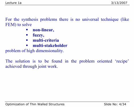
For the synthesis problems there is no universal technique (like FEM) to solve
non-linear, fuzzy, multi-criteria multi-stakeholder
problem of high dimensionality. The solution is to be found in the problem oriented ‘recipe’ achieved through joint work.
Lecture 1a 3/13/2007
Optimization of Thin Walled Structures Slide No: 5/34
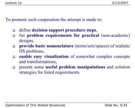
To promote such cooperation the attempt is made to:
define decision support procedure steps, list problem requirements for practical (non-academic)
designs, provide basic nomenclature (terms/sets/spaces) of realistic
DS problems, enable easy visualization of somewhat complex concepts
and transformations, present some useful problem manipulations and solution
strategies for listed requirements.
Lecture 1a 3/13/2007
Optimization of Thin Walled Structures Slide No: 6/34
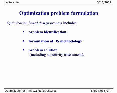
Optimization problem formulation
Optimization based design process includes:
problem identification, formulation of DS methodology
problem solution
(including sensitivity assessment).
Lecture 1a 3/13/2007
Optimization of Thin Walled Structures Slide No: 7/34
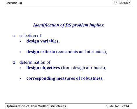
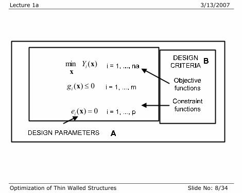
Identification of DS problem implies:
selection of design variables,
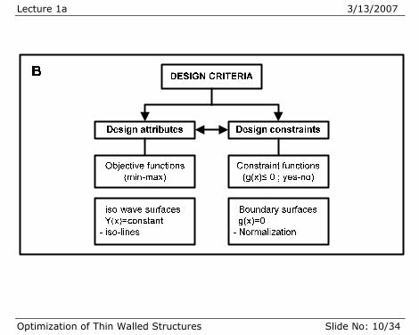
design criteria (constraints and attributes),
determination of
design objectives (from design attributes), corresponding measures of robustness.
Lecture 1a 3/13/2007
Optimization of Thin Walled Structures Slide No: 8/34
)(min xx
iY
0)( ≤xig
0)( =xie
Lecture 1a 3/13/2007
Optimization of Thin Walled Structures Slide No: 9/34
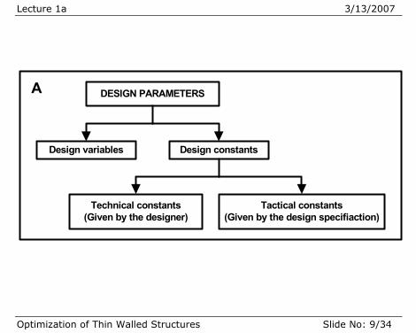
DESIGN PARAMETERS
Design variables Design constants
Technical constants(Given by the designer)
Tactical constants(Given by the design specifiaction)
A
Lecture 1a 3/13/2007
Optimization of Thin Walled Structures Slide No: 10/34
Lecture 1a 3/13/2007
Optimization of Thin Walled Structures Slide No: 11/34
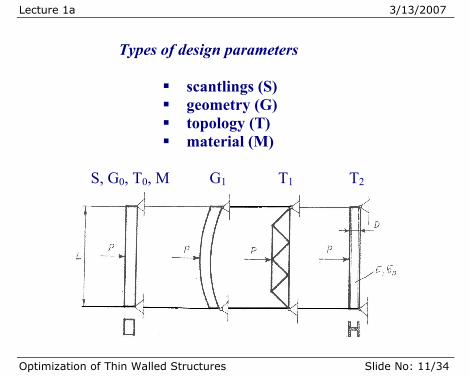
Types of design parameters
scantlings (S) geometry (G) topology (T) material (M)
S, G0, T0, M G1 T1 T2
Lecture 1a 3/13/2007
Optimization of Thin Walled Structures Slide No: 12/34
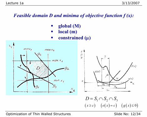
Feasible domain D and minima of objective function f (x):
global (M) local (m) constrained (μ)
1 2 3D S S S= ∩ ∩ ( )x c≥ ( )( )e x c= ( )( )0g x ≤
Lecture 1a 3/13/2007
Optimization of Thin Walled Structures Slide No: 13/34
Formulation of Decision Support Methodology DS methodology can be efficiently formulated after the basic characteristics of design requirements & designer's preferences are revealed. It involves:
DS problem manipulation into equivalent but mathematically more convenient form,
selection of solution strategy (e.g. optimization technique)
for the manipulated problem,
development of the final selection method for the generated design variants (preferred designs ,
sensitivity / uncertainty analysis.
Lecture 1a 3/13/2007
Optimization of Thin Walled Structures Slide No: 14/34
DS problem solution
Requires practical implementation of selected methodology through two basic calculation (mathematical) models:
Design analysis model for: technical (safety, weight, etc.) evaluations economical (cost) evaluations
Synthesis model which includes:
interactive decision-making shell design utilities (optimization and sensitivity
modules, databases, graphics, etc.).
Lecture 1a 3/13/2007
Optimization of Thin Walled Structures Slide No: 15/34
Basic requirements on practical calculation models
Response calculations for large complex structural models (e.g. 10-deck passenger ship)
Stochastic definition of loading (ship in a seaway) for reliability comparisons
Numerous safety criteria checks, including ultimate strength, based on library of various modes of failure under combined loads (e.g. few hundred thousand safety checks).
Safety criteria might be expressed in the deterministic or reliability formats, which however imply time consuming reliability calculations, even for semi probabilistic approach.
Lecture 1a 3/13/2007
Optimization of Thin Walled Structures Slide No: 16/34
Basic requirements on practical calculation
models
Structural redundancy and plastic collapse mechanisms should also be assessed as ultimate strength criteria involving time consuming non-linear models.
Some form of system reliability should also be included in the design process.
Design criteria should include relevant aspects of design, besides safety, such as building cost, maintenance cost, weight, ship stability, etc. implying multi-criteria approach.
Lecture 1a 3/13/2007
Optimization of Thin Walled Structures Slide No: 17/34
Basic requirements on practical calculation
models
Design variables should include geometry of structure, scantlings of structural elements, material selection
However, topology (layout) of structural elements is usually fixed for the structural designer by requirements of principal designer.
Variables used could be continuous or discrete (e.g. number of stiffeners) or given by available values (e.g. thickness of plates, available rolled profiles, etc.).
Dimensionality can reach thousands of design variables.
Lecture 1a 3/13/2007
Optimization of Thin Walled Structures Slide No: 18/34
Basic requirements on practical calculation
models
Final selection of preferred design is influenced by subjective reasoning of structural and general designer, owners and shipyard management. Accommodation for subjective decisions should be part of the design process.
Design method should be practical for use in design offices, easily modified and interactive
Design method should be applicable in case studies of advanced concepts capable of expansion to new criteria and methods.
Lecture 1a 3/13/2007
Optimization of Thin Walled Structures Slide No: 19/34
Basic requirements on practical calculation
models
Each good new design contains its own ‘grain of salt’ and the flexibility of the design model definition should be one of the first priorities to accommodate such design needs.
Basic analysis tools, such as FEM, also affect design procedure via required accuracy of stress/displacement/vibration levels and as a time penalty in synthesis algorithms.
Lecture 1a 3/13/2007
Optimization of Thin Walled Structures Slide No: 20/34
DS problem solution advantages
In meeting these conflicting requirements the advances in
modern engineering hardware should also be taken into account.
Design procedure requires only a comparison of competing
designs, therefore relative and not absolute values of design attributes are needed. All considerations that are the same, or similar, for different designs could be excluded from the design process.
The real quality of the design process is not based on inclusion of all possible or available complex calculations but, on the contrary, on a reasonable exclusion of all unnecessary considerations by concentrating on relevant ones used in key decisions on the design characteristics.
Lecture 1a 3/13/2007
Optimization of Thin Walled Structures Slide No: 21/34
DS problem solution advantages
Development of parallel processing on modern computers or
parallel work on workstations fit very well with design methods where, despite the spiral character of the overall design process, many of the calculation steps are parallel in nature.
The increased speed of clusters of engineering workstations is opening the possibility of incorporating complex design criteria into realistic design procedure.
Lecture 1a 3/13/2007
Optimization of Thin Walled Structures Slide No: 22/34
DESIGN ANALYSIS MODULES
Complexity of synthesis procedure shown through its
dimensionality,
nonlinearity of response and feasibility models,
stochastic definition of loading and material,
subjectivity of quality assessments permit only certain combinations of analytical and synthesis modules in DS problem formulations for different phases of design process.
Lecture 1a 3/13/2007
Optimization of Thin Walled Structures Slide No: 23/34
Design phases
Concept design is the phase in structural design when
geometry and topology are open to modification structural variants are analyzed in accordance with needs of
general design. applied loads are usually taken as deterministic
Selection of appropriate scantlings is only important for
approximate assessment of structural weight, achievable clearances regarding height of beams and
girders in structure etc. with a goal to define best structural layout.
Benefits of optimization procedure in this phase are the biggest (Krueger 2001).
Lecture 1a 3/13/2007
Optimization of Thin Walled Structures Slide No: 24/34
Design phases
Reliability based concept design
In theory, full probabilistic analysis (FPA) is always superior to any lower level method of equal level of complexity due to higher threshold of realism for phenomena defined in uncertain environment.
FPA methods will not become replacement for simple
deterministic models due to complexity of decisions to be made and due to underlined need for simplicity.
Compromise in concept design phase can be in performing
reliability-based design with aim only to compare designs, while value of failure probability is only approximate.
The only requirement on such analysis is that design variants
maintain mutual order w.r.t failure probability.
Lecture 1a 3/13/2007
Optimization of Thin Walled Structures Slide No: 25/34
Design phases
Preliminary design
It is the phase in structural design when most scantlings and
some topological variables are determined to obtain the approval of the structure from classification societies.
Topological variables can typically be number or type of stiffeners in stiffened panels and sometimes stiffener orientation.
Lecture 1a 3/13/2007
Optimization of Thin Walled Structures Slide No: 26/34
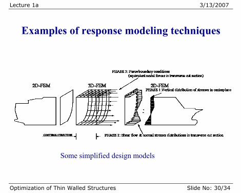
Response modeling techniques
Classical finite element modeling, giving good insight into
stresses and deformations is not capable of giving efficient and fast answers regarding feasibility criteria particularly in structural optimization context.
Most of the local failure criteria, e.g. different buckling failure
modes of stiffened panels, require specified force and displacement boundary conditions.
They are available only if logical structural parts such as
complete stiffened panels between girders and frames are modeled. This mesh size is also sufficient for vibration analysis.
Lecture 1a 3/13/2007
Optimization of Thin Walled Structures Slide No: 27/34
Response modeling techniques
Super-element modeling may help in this respect but it is
usually impractical except for some particularly complex parts where stress or deformation levels are needed.
Specially developed macroelements, combining numerical and
analytical approaches to logical meta-structures: o stiffened panels, o bracketed and locally reinforced girders, o cell elements,
could be a fruitful alternative. Their use is grossly simplifying and speeding up design work in all described design procedure.
Lecture 1a 3/13/2007
Optimization of Thin Walled Structures Slide No: 28/34
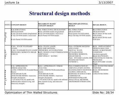
Structural design methods
MODUL CONCEPT DESIGN RELIABILITY BASED
CONCEPT DESIGN PRELIMINARY/INITIAL DESIGN DETAIL DESIGN
M O D E L
C.1: STRUCTURAL IDEALIZATION C.1.1: 2D FEM models (longitudinal) C 1.2: 2D FEM models ( transverse) C.1.3: Partial 3D FEM models
R.1: STRUCTURAL IDEALIZATION R.1.1: 2D FEM models (longitudinal) R 1.2: 2D FEM models ( transverse) R.1.3: Partial 3D FEM models
P.1: STRUCTURAL IDEALIZATION P.1.1: partial 3D FEM models P.1.2: full ship 3D FEM models
D.1: STRUCTURAL IDEALIZATION D.1.1: partial 3D fine mesh FEM models D.1.2: partial 2D fine mesh FEM mod.
L O A D S
C.2.1: STATIC STANDARD LOADS C.2.2: STANDARD WAVE LOADS PRESSURES, MOMENTS, SHEAR FORCES
R.2.1: STATIC LOADS R.2.2: SHIP MOTIONS, PRESSURES, ACCELERATIONS R.2.3: DESIGN LOAD COMBINATIONS-SHIP’S RAO -SHIP OPERAT. MATRIX
P.2.1: EXTREME MOTIONS AND LOADS : EQUIVAL. WAVE, ACCELERATIONS, PRESSURES, MOMENTS, SHEAR FORCES P.2.2: DYNAMIC LOADS ANDPHASING BETWEEN EXTREME L.
D.2.1: DISPLACEMENT FROM GLOBAL FEM MODEL AS BOUNDARY CONDITION (top-down approach) D.2.2: SELFWEIGHT, CONCENTRATE FORCES, PRESSURES D.2.3: DYNAMIC LOADS-fatigue
R E S P O N S E
C.3.1 APPROXIMATE STRESS ANALYSIS: -LONG. STRENGTH (Extended Beam theory) -FEM SHEAR FLOW -FEM FRAME MODEL- transverse strength calculations - 3-D ANALYTICAL model with stiffened plate element (Long. and transverse strength)
R.3.1 1 APPROXIMATE STRESS ANALYSIS: -LONG. STRENGTH (Extended Beam theory) -FEM SHEAR FLOW -FEM FRAME MODEL- transverse strength calculations - 3-D ANALYTICAL model with stiffened plate element (Long. and transverse strength)
P.3.1: COMBINATION OF : -SHIP (FULL/PART) 3D FEM MACROELEMENT RESPONSE -GLOBAL AND LOCAL RESPONSE OF STRUCTURES COMPOSED OF STIFFENED PANELS BY ANALYTICAL METHODS -MICROMESH STRESS CONC.
D.3.1: 3D FEM FINE MESH RESPONSE D.3.2 : MICROMESH STRESS CONCENTRATIONS
Lecture 1a 3/13/2007
Optimization of Thin Walled Structures Slide No: 29/34
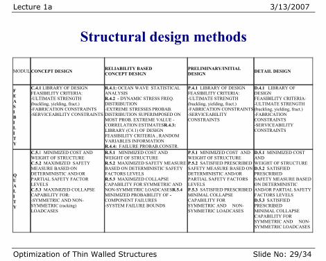
Structural design methods
MODUL CONCEPT DESIGN RELIABILITY BASED
CONCEPT DESIGN PRELIMINARY/INITIAL DESIGN DETAIL DESIGN
F E A S I B I L I T Y
C.4.1 LIBRARY OF DESIGN FEASIBILITY CRITERIA: -ULTIMATE STRENGTH (buckling, yielding, fract.) -FABRICATION CONSTRAINTS -SERVICEABILITY CONSTRAINTS
R.4.1: OCEAN WAVE STATISTICAL ANALYSIS R.4.2 - DYNAMIC STRESS FREQ. DISTRIBUTION -EXTREME STRESSES PROBAB. DISTRIBUTION SUPERIMPOSED ON MOST PROB. EXTREME VALUE - CORRELATION ESTIMATESR.4.3: LIBRARY (C4.1) OF DESIGN FEASIBILITY CRITERIA , RANDOM VARIABLES INFORMATION R.4.4: FAILURE PROBAB.CONSTR.
P.4.1 LIBRARY OF DESIGN FEASIBILITY CRITERIA: -ULTIMATE STRENGTH (buckling, yielding, fract.) -FABRICATION CONSTRAINTS-SERVICEABILITY CONSTRAINTS
D.4.1 LIBRARY OF DESIGN FEASIBILITY CRITERIA: -ULTIMATE STRENGTH (buckling, yielding, fract.) -FABRICATION CONSTRAINTS -SERVICEABILITY CONSTRAINTS
Q U A L I T Y
C.5.1 MINIMIZED COST AND WEIGHT OF STRUCTURE C.5.2 MAXIMIZED SAFETY MEASURE BASED ON DETERMINISTIC AND/OR PARTIAL SAFETY FACTOR LEVELS C.5.3 MAXIMIZED COLLAPSE CAPABILITY FOR: -SYMMETRIC AND NON- SYMMETRIC (racking) LOADCASES
R.5.1 MINIMIZED COST AND WEIGHT OF STRUCTURE R.5.2 MAXIMIZED SAFETY MEASURE BASED ON DETERMINISTIC SAFETY FACTORS LEVELS R.5.3 MAXIMIZED COLLAPSE CAPABILITY FOR SYMMETRIC AND NON-SYMMETRIC LOADCASESR.5.4 MINIMIZED PROBABILITY OF -COMPONENT FAILURES -SYSTEM FAILURE BOUNDS
P.5.1 MINIMIZED COST AND WEIGHT OF STRUCTURE P.5.2 SATISFIED PRESCRIBEDSAFETY MEASURE BASED ON DETERMINISTIC AND/OR PARTIAL SAFETY FACTORS LEVELS P.5.3 SATISFIED PRESCRIBEDMINIMAL COLLAPSE CAPABILITY FOR SYMMETRIC AND NON-SYMMETRIC LOADCASES
D.5.1 MINIMIZED COST AND WEIGHT OF STRUCTURE D.5.2 SATISFIED PRESCRIBED SAFETY MEASURE BASED ON DETERMINISTIC AND/OR PARTIAL SAFETY FACTORS LEVELS D.5.3 SATISFIED PRESCRIBED MINIMAL COLLAPSE CAPABILITY FOR SYMMETRIC AND NON-SYMMETRIC LOADCASES
Lecture 1a 3/13/2007
Optimization of Thin Walled Structures Slide No: 30/34
Examples of response modeling techniques
Some simplified design models
Lecture 1a 3/13/2007
Optimization of Thin Walled Structures Slide No: 31/34
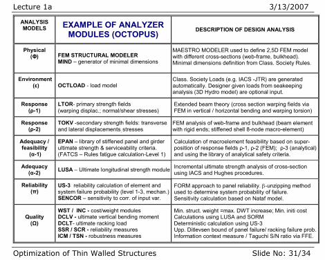
ANALYSIS MODELS EXAMPLE OF ANALYZER
MODULES (OCTOPUS) DESCRIPTION OF DESIGN ANALYSIS
Physical (Φ) FEM STRUCTURAL MODELER
MIND – generator of minimal dimensions
MAESTRO MODELER used to define 2,5D FEM model with different cross-sections (web-frame, bulkhead). Minimal dimensions definition from Class. Society Rules.
Environment (ε) OCTLOAD - load model
Class. Society Loads (e.g. IACS -JTR) are generated automatically. Designer given loads from seakeeping analysis (3D Hydro model) are optional input.
Response (ρ-1)
LTOR- primary strength fields (warping displac.; normal/shear stresses)
Extended beam theory (cross section warping fields via FEM in vertical / horizontal bending and warping torsion)
Response (ρ-2)
TOKV -secondary strength fields: transverse and lateral displacements; stresses
FEM analysis of web-frame and bulkhead (beam element with rigid ends; stiffened shell 8-node macro-element)
Adequacy / feasibility
(α-1)
EPAN – library of stiffened panel and girder ultimate strength & serviceability criteria. (FATCS – Rules fatigue calculation-Level 1)
Calculation of macroelement feasibility based on super-position of response fields ρ-1, ρ-2 (FEM); ρ-3 (analytical) and using the library of analytical safety criteria.
Adequacy (α-2) LUSA – Ultimate longitudinal strength module Incremental ultimate strength analysis of cross-section
using IACS and Hughes procedures.
Reliability (π)
US-3 reliability calculation of element and system failure probability (level 1-3, mechan.)SENCOR – sensitivity to corr. of input var.
FORM approach to panel reliability. β-unzipping method used to determine system probability of failure. Sensitivity calculation based on Nataf model.
Quality
(Ω)
WST / INC - cost/weight modules DCLV - ultimate vertical bending moment DCLT- ultimate racking load SSR / SCR - reliability measures ICM / TSN - robustness measures
Min. struct. weight =max. DWT increase; Min. initi cost Calculations using LUSA and SORM Deterministic calculation using US-3 Upp. Ditlevsen bound of panel failure/ racking failure prob.Information context measure / Taguchi S/N ratio via FFE.
Lecture 1a 3/13/2007
Optimization of Thin Walled Structures Slide No: 32/34
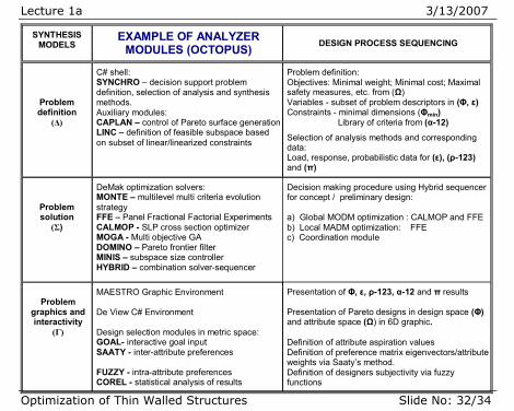
SYNTHESIS MODELS
EXAMPLE OF ANALYZER MODULES (OCTOPUS) DESIGN PROCESS SEQUENCING
Problem definition
(Δ)
C# shell: SYNCHRO – decision support problem definition, selection of analysis and synthesis methods. Auxiliary modules: CAPLAN – control of Pareto surface generationLINC – definition of feasible subspace based on subset of linear/linearized constraints
Problem definition: Objectives: Minimal weight; Minimal cost; Maximal safety measures, etc. from (Ω) Variables - subset of problem descriptors in (Φ, ε) Constraints - minimal dimensions (Φmin) Library of criteria from (α-12)
Selection of analysis methods and corresponding data: Load, response, probabilistic data for (ε), (ρ-123) and (π)
Problem solution
(Σ)
DeMak optimization solvers: MONTE – multilevel multi criteria evolution strategy FFE – Panel Fractional Factorial Experiments CALMOP - SLP cross section optimizer MOGA - Multi objective GA DOMINO – Pareto frontier filter MINIS – subspace size controller HYBRID – combination solver-sequencer
Decision making procedure using Hybrid sequencer for concept / preliminary design: a) Global MODM optimization : CALMOP and FFE b) Local MADM optimization: FFE c) Coordination module
Problem
graphics and interactivity
(Γ)
MAESTRO Graphic Environment De View C# Environment Design selection modules in metric space: GOAL- interactive goal input SAATY - inter-attribute preferences FUZZY - intra-attribute preferences COREL - statistical analysis of results
Presentation of Φ, ε, ρ-123, α-12 and π results Presentation of Pareto designs in design space (Φ) and attribute space (Ω) in 6D graphic. Definition of attribute aspiration values Definition of preference matrix eigenvectors/attribute weights via Saaty’s method. Definition of designers subjectivity via fuzzy functions
Lecture 1a 3/13/2007
Optimization of Thin Walled Structures Slide No: 33/34
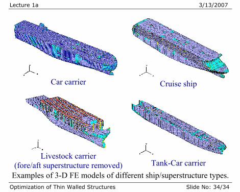
Examples of response modeling techniques
Four extreme models of multideck ships were selected according to different superstructure/lower hull arrangement for calibration of the generic design models to different ship type’s:
Model 1 – basic (e.g. car carrier) closed superstructure with sides
without openings or with side ramp;
Model 2 (livestock carrier) open superstructure on pillar arrangement, high reduction of shear stiffness of superstructure sides, decks weakly restrained fore/aft;
Model 3 (cruise ship) large openings in superstructure sides, internal empty spaces, non alignment of side walls of the superstructure with the hull sides due to life boat recess;
Model 4 (tank-car carrier) very long deck house on the very flexible upper deck.
Lecture 1a 3/13/2007
Optimization of Thin Walled Structures Slide No: 34/34
Car carrier Cruise ship
Livestock carrier
(fore/aft superstructure removed) Tank-Car carrier Examples of 3-D FE models of different ship/superstructure types.