Embed Size (px)
Citation preview
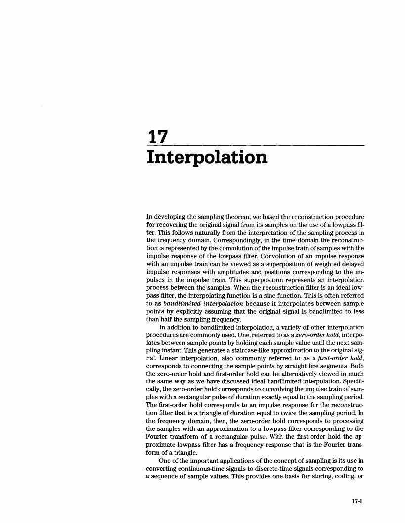
17Interpolation
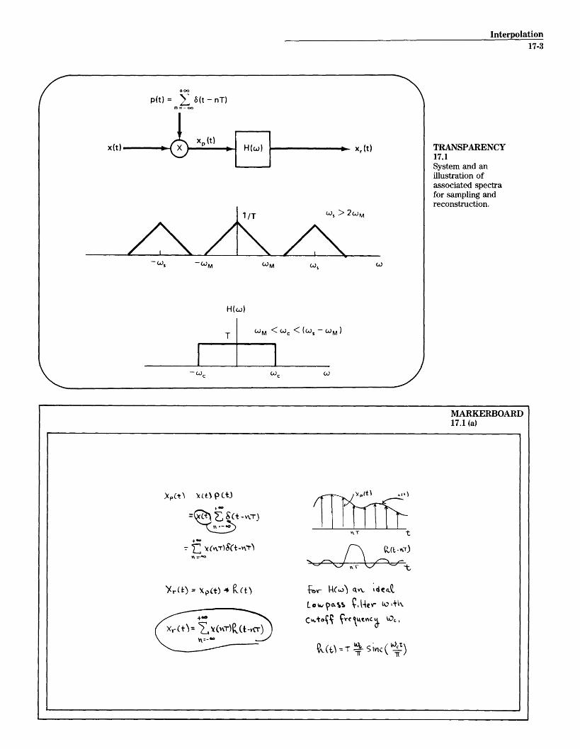
In developing the sampling theorem, we based the reconstruction procedurefor recovering the original signal from its samples on the use of a lowpass fil-ter. This follows naturally from the interpretation of the sampling process inthe frequency domain. Correspondingly, in the time domain the reconstruc-tion is represented by the convolution of the impulse train of samples with theimpulse response of the lowpass filter. Convolution of an impulse responsewith an impulse train can be viewed as a superposition of weighted delayedimpulse responses with amplitudes and positions corresponding to the im-pulses in the impulse train. This superposition represents an interpolationprocess between the samples. When the reconstruction filter is an ideal low-pass filter, the interpolating function is a sinc function. This is often referredto as bandlimited interpolation because it interpolates between samplepoints by explicitly assuming that the original signal is bandlimited to lessthan half the sampling frequency.
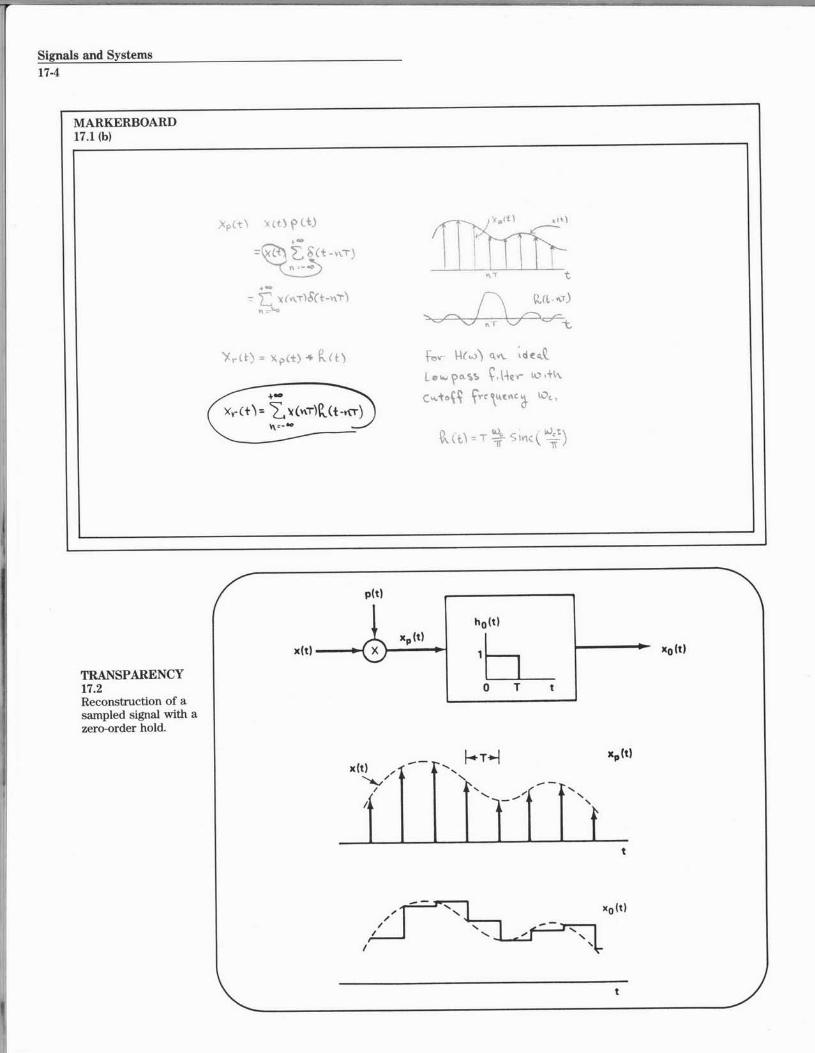
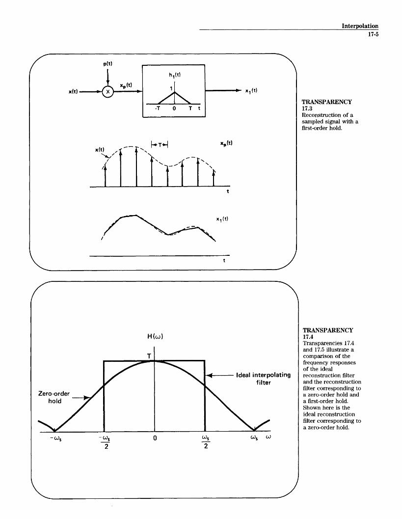
In addition to bandlimited interpolation, a variety of other interpolationprocedures are commonly used. One, referred to as a zero-order hold, interpo-lates between sample points by holding each sample value until the next sam-pling instant. This generates a staircase-like approximation to the original sig-nal. Linear interpolation, also commonly referred to as a first-order hold,corresponds to connecting the sample points by straight line segments. Boththe zero-order hold and first-order hold can be alternatively viewed in muchthe same way as we have discussed ideal bandlimited interpolation. Specifi-cally, the zero-order hold corresponds to convolving the impulse train of sam-ples with a rectangular pulse of duration exactly equal to the sampling period.The first-order hold corresponds to an impulse response for the reconstruc-tion filter that is a triangle of duration equal to twice the sampling period. Inthe frequency domain, then, the zero-order hold corresponds to processingthe samples with an approximation to a lowpass filter corresponding to theFourier transform of a rectangular pulse. With the first-order hold the ap-proximate lowpass filter has a frequency response that is the Fourier trans-form of a triangle.
One of the important applications of the concept of sampling is its use inconverting continuous-time signals to discrete-time signals corresponding toa sequence of sample values. This provides one basis for storing, coding, or
17-1
Signals and Systems17-2
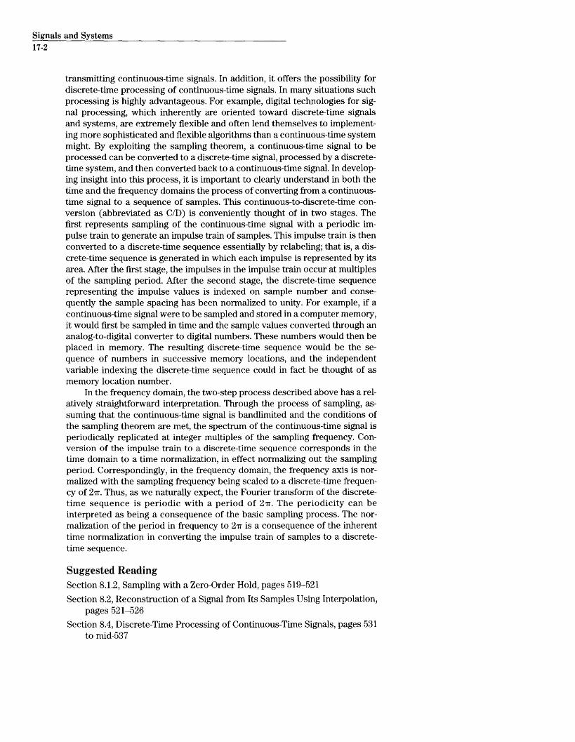
transmitting continuous-time signals. In addition, it offers the possibility fordiscrete-time processing of continuous-time signals. In many situations suchprocessing is highly advantageous. For example, digital technologies for sig-nal processing, which inherently are oriented toward discrete-time signalsand systems, are extremely flexible and often lend themselves to implement-ing more sophisticated and flexible algorithms than a continuous-time systemmight. By exploiting the sampling theorem, a continuous-time signal to beprocessed can be converted to a discrete-time signal, processed by a discrete-time system, and then converted back to a continuous-time signal. In develop-ing insight into this process, it is important to clearly understand in both thetime and the frequency domains the process of converting from a continuous-time signal to a sequence of samples. This continuous-to-discrete-time con-version (abbreviated as C/D) is conveniently thought of in two stages. Thefirst represents sampling of the continuous-time signal with a periodic im-pulse train to generate an impulse train of samples. This impulse train is thenconverted to a discrete-time sequence essentially by relabeling; that is, a dis-crete-time sequence is generated in which each impulse is represented by itsarea. After the first stage, the impulses in the impulse train occur at multiplesof the sampling period. After the second stage, the discrete-time sequencerepresenting the impulse values is indexed on sample number and conse-quently the sample spacing has been normalized to unity. For example, if acontinuous-time signal were to be sampled and stored in a computer memory,it would first be sampled in time and the sample values converted through ananalog-to-digital converter to digital numbers. These numbers would then beplaced in memory. The resulting discrete-time sequence would be the se-quence of numbers in successive memory locations, and the independentvariable indexing the discrete-time sequence could in fact be thought of asmemory location number.
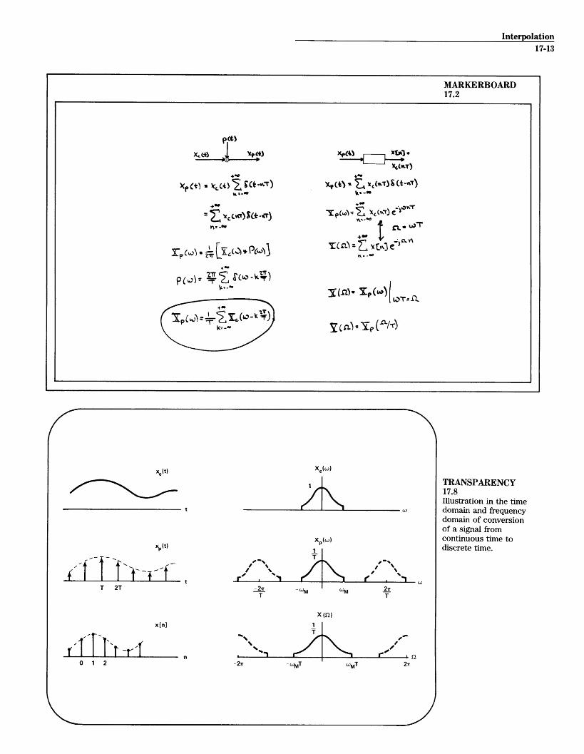
In the frequency domain, the two-step process described above has a rel-atively straightforward interpretation. Through the process of sampling, as-suming that the continuous-time signal is bandlimited and the conditions ofthe sampling theorem are met, the spectrum of the continuous-time signal isperiodically replicated at integer multiples of the sampling frequency. Con-version of the impulse train to a discrete-time sequence corresponds in thetime domain to a time normalization, in effect normalizing out the samplingperiod. Correspondingly, in the frequency domain, the frequency axis is nor-malized with the sampling frequency being scaled to a discrete-time frequen-cy of 2Tr. Thus, as we naturally expect, the Fourier transform of the discrete-time sequence is periodic with a period of 2 7r. The periodicity can beinterpreted as being a consequence of the basic sampling process. The nor-malization of the period in frequency to 27r is a consequence of the inherenttime normalization in converting the impulse train of samples to a discrete-time sequence.
Suggested ReadingSection 8.1.2, Sampling with a Zero-Order Hold, pages 519-521
Section 8.2, Reconstruction of a Signal from Its Samples Using Interpolation,pages 521-526
Section 8.4, Discrete-Time Processing of Continuous-Time Signals, pages 531to mid-537
Interpolation17-3
+oo0
P(t) 6(t - nT)n=- oo
X,(t)
WS > 2WM
M WS
H(W)
WM < Wc < (w M - M)
TRANSPARENCY17.1System and anillustration ofassociated spectrafor sampling andreconstruction.
-Ac ( cC
+* 4
t
LOI~J ~qO4 - 4ec(O+k
Cvvto 1 Ww ~ LO,,for i 7~)n de
MARKERBOARD17.1 (a)
Signals and Systems17-4
(t
t
Y, )
TRANSPARENCY17.2Reconstruction of asampled signal with azero-order hold.
p(t)
x(t)
x(t) -/M
AfNI -'
Nf N.v~FiNN%.l
- N x0 (t)/
%.~ - NN
/
MARKERBOARD17.1 (b)
X0 ()
xp(t)
___j
Xrct)=
Interpolation17-5
p(t)
x1(t)
XP(t)T*]
x, (t)
TRANSPARENCY17.3Reconstruction of asampled signal with afirst-order hold.
H (co)
I ____________ I ____________
Ideal interpolatingf ilter
cis cO
TRANSPARENCY17.4Transparencies 17.4and 17.5 illustrate acomparison of thefrequency responsesof the idealreconstruction filterand the reconstructionfilter corresponding toa zero-order hold anda first-order hold.Shown here is theideal reconstructionfilter corresponding toa zero-order hold.
x(t)
x(t)
Zero-orderhold
- WS
2
/- --
Signals and Systems
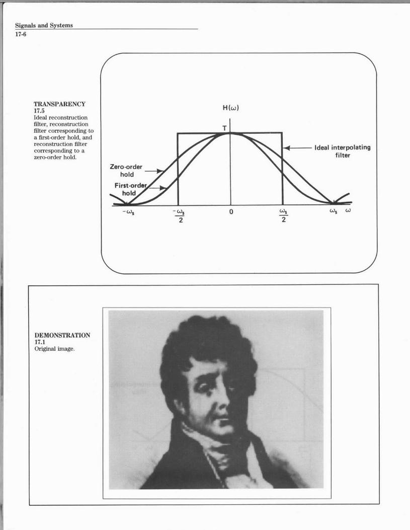
TRANSPARENCY H (w)17.5Ideal reconstructionfilter, reconstruction Tfilter corresponding -toa first-order hold, andreconstruction filtercorresponding to azero-order hold.
- W, 0 Cs ws w2 2
Ideal interpolatingfilter
DEMONSTRATION17.1Original image.
Interpolation17-7
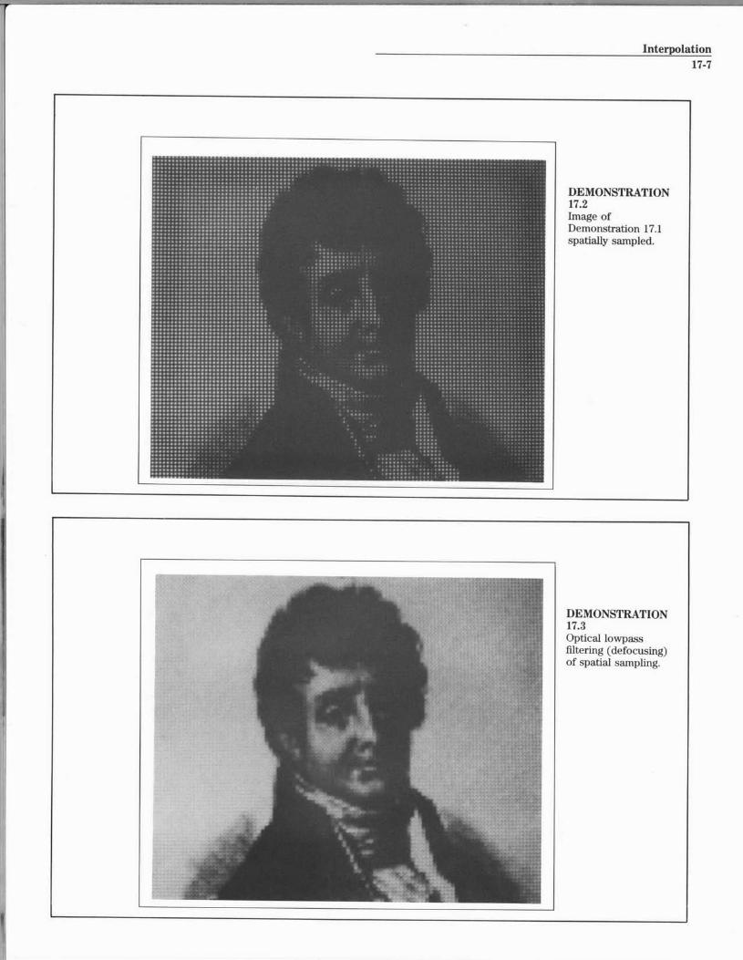
DEMONSTRATION17.2Image ofDemonstration 17.1spatially sampled.
DEMONSTRATION17.3Optical lowpassfiltering (defocusing)of spatial sampling.
Signals and Systems17-8
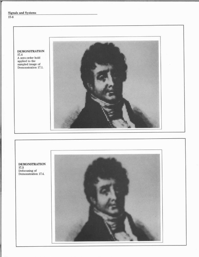
DEMONSTRATION17.5Defocusing ofDemonstration 17.4.
Interpolation17-9
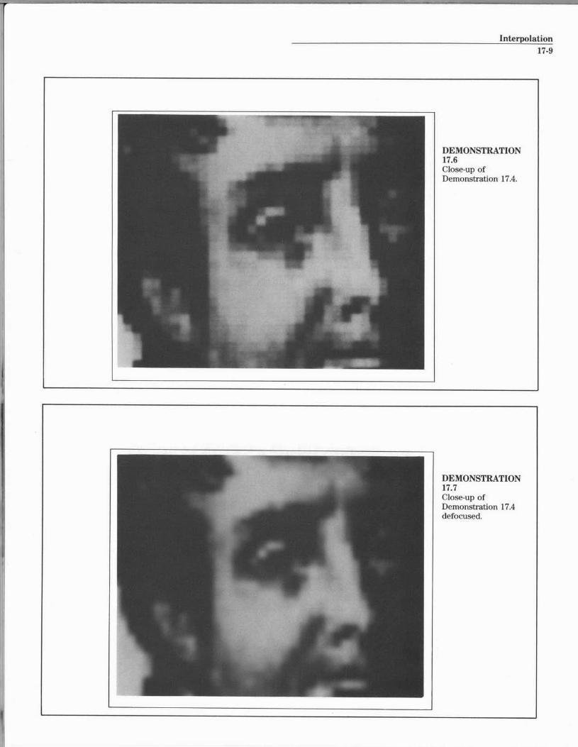
DEMONSTRATION17.7Close-up ofDemonstration 17.4defocused.
Signals and Systems
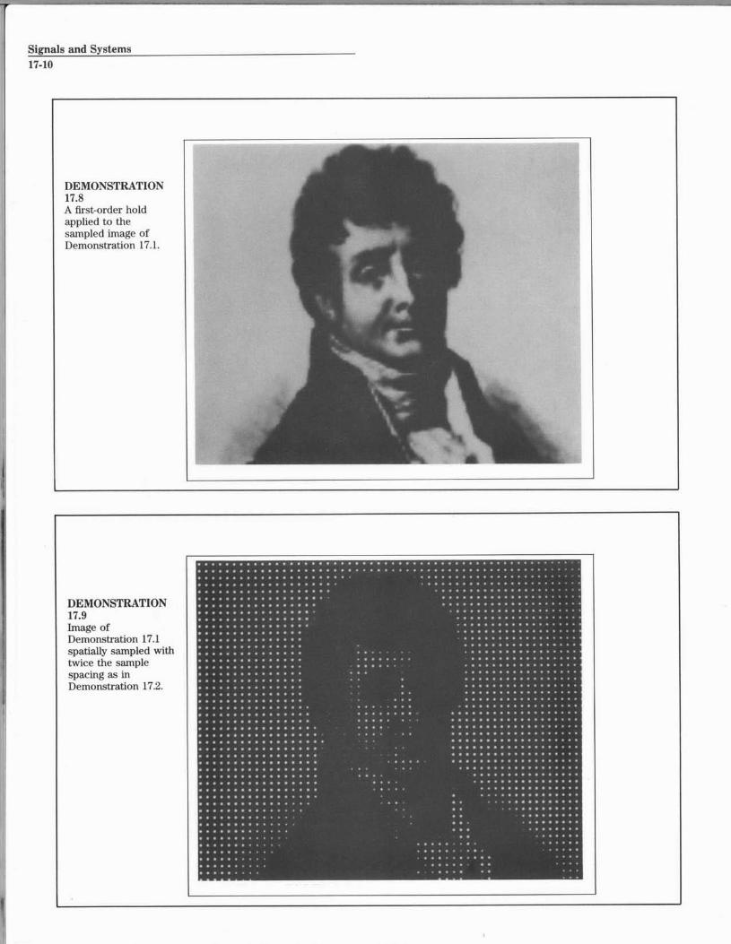
DEMONSTRATION17.8A first-order holdapplied to thesampled image ofDemonstration 17.1.
DEMONSTRATION17.9Image ofDemonstration 17.1spatially sampled withtwice the samplespacing as inDemonstration 17.2.
I
I
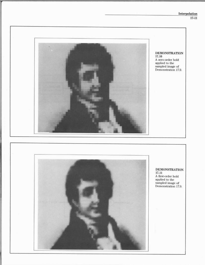
Interpolation17-11
DEMONSTRATION17.11A first-order holdapplied to thesampled image ofDemonstration 17.9.
Signals and Systems
17-12
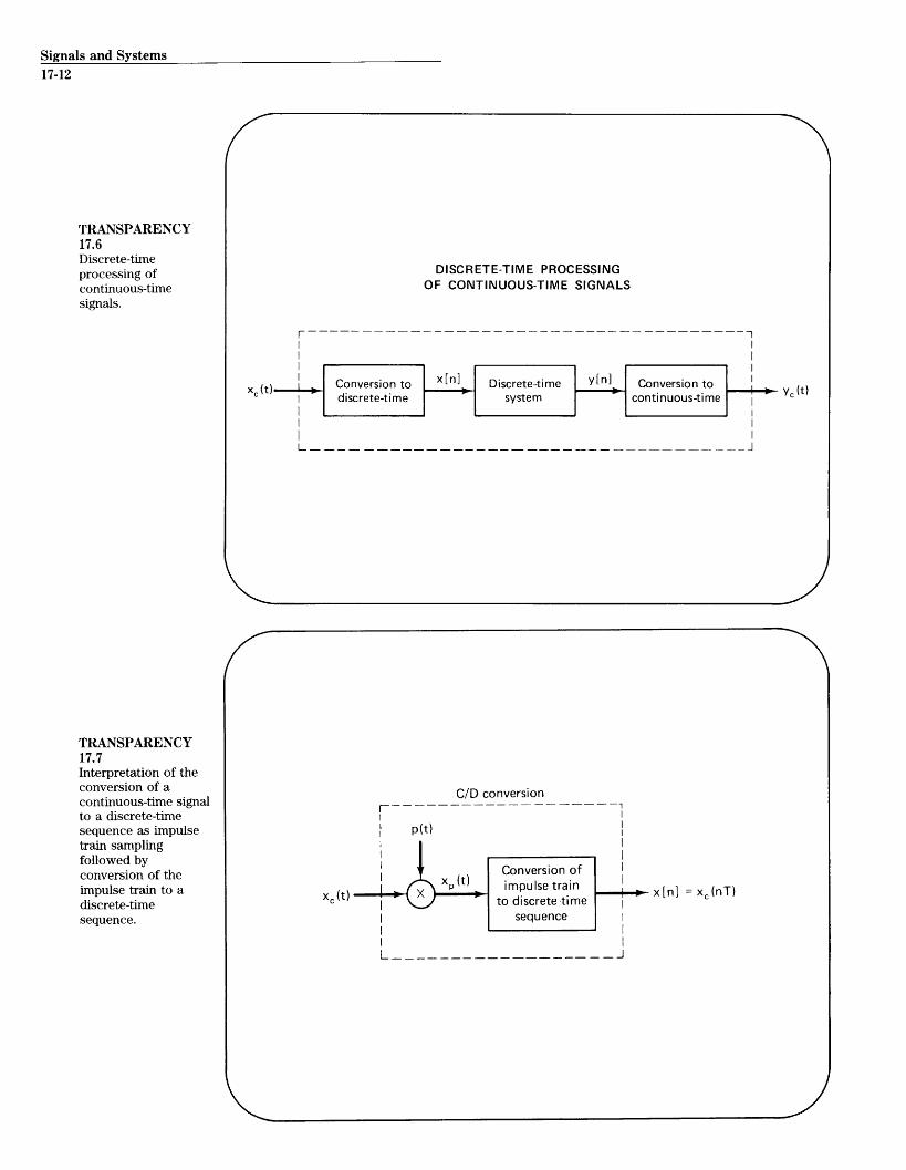
TRANSPARENCY17.6Discrete-timeprocessing ofcontinuous-timesignals.
TRANSPARENCY17.7Interpretation of theconversion of acontinuous-time signalto a discrete-timesequence as impulsetrain samplingfollowed byconversion of theimpulse train to adiscrete-timesequence.
DISCRETE-TIME PROCESSINGOF CONTINUOUS-TIME SIGNALS
Conversion to x[n] Discrete-time y[n] Conversion to y (t)discrete-time system continuous-time
L- _ - - __ J
C/D conversion
p(t)
Conversion ofx t) I xP(t) impulse train x[n] xc(nT)
c--- to discrete-timex
sequence
Interpolation
17-13
pct)
e t c(4 5 Zg.t-a
W24
440
xx 3-
T
+ '--*
0(0~
XC). p(o
x (w)xM(t)
x (w)
T 2T
x[n]
0 1 2
1
L-N-
TRANSPARENCY17.8Illustration in the timedomain and frequencydomain of conversionof a signal fromcontinuous time todiscrete time.
MARKERBOARD17.2
__j
MIT OpenCourseWare http://ocw.mit.edu
Resource: Signals and Systems Professor Alan V. Oppenheim
The following may not correspond to a particular course on MIT OpenCourseWare, but has been provided by the author as an individual learning resource.
For information about citing these materials or our Terms of Use, visit: http://ocw.mit.edu/terms.