Embed Size (px)
Citation preview

Lecture 16: WPAN IEEE 802.15 (Bluetooth &
ZigBee)Anders Vä[email protected]
08-790 44 55
Slides are a selection from the slides from chapter 15 from:http://williamstallings.com/Wireless/Wireless2e.html

802.15 Protocol Architecture

IEEE 802.15

Bluetooth Overview
• Universal short-range wireless capability• Uses 2.4-GHz band• Available globally for unlicensed users• Devices within 10 m can share up to 720 kbps
of capacity (v2.1 – 3 Mbit/s, v3+ 24 Mbit/s)• Supports open-ended list of applications
– Data, audio, graphics, video

Bluetooth Application Areas
• Data and voice access points– Real-time voice and data transmissions
• Cable replacement– Eliminates need for numerous cable attachments
for connection• Ad hoc networking
– Device with Bluetooth radio can establish connection with another when in range

Bluetooth Standards Documents
• Core specifications– Details of various layers of Bluetooth protocol
architecture• Profile specifications
– Use of Bluetooth technology to support various applications
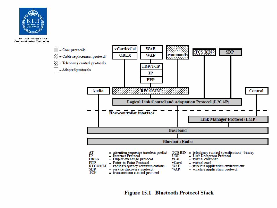

Protocol Architecture• Bluetooth is a layered protocol architecture
– Core protocols– Cable replacement and telephony control protocols– Adopted protocols
• Core protocols– Radio– Baseband– Link manager protocol (LMP)– Logical link control and adaptation protocol (L2CAP)– Service discovery protocol (SDP)

Protocol Architecture• Cable replacement protocol
– RFCOMM• Telephony control protocol
– Telephony control specification – binary (TCS BIN)• Adopted protocols
– PPP– TCP/UDP/IP– OBEX– WAE/WAP

Usage Models
• File transfer• Internet bridge• LAN access• Synchronization• Three-in-one phone (Cordless, Phone2Phone,
Cellular)• Headset

Usage Models

Piconets and Scatternets
• Piconet– Basic unit of Bluetooth networking– Master and one to seven slave devices– Master determines channel and phase
• Scatternet– Device in one piconet may exist as master or slave in
another piconet– Allows many devices to share same area– Makes efficient use of bandwidth

Wireless Network Configurations

Radio Specification
• Classes of transmitters– Class 1: Outputs 100 mW for maximum range
• Power control mandatory• Provides greatest distance
– Class 2: Outputs 2.4 mW at maximum• Power control optional
– Class 3: Nominal output is 1 mW• Lowest power

Frequency Hopping in Bluetooth
• Provides resistance to interference and multipath effects
• Provides a form of multiple access among co-located devices in different piconets
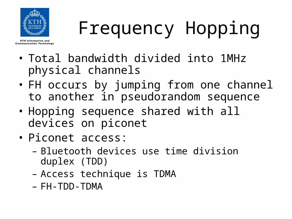
Frequency Hopping• Total bandwidth divided into 1MHz physical channels• FH occurs by jumping from one channel to another in
pseudorandom sequence• Hopping sequence shared with all devices on piconet• Piconet access:
– Bluetooth devices use time division duplex (TDD)– Access technique is TDMA– FH-TDD-TDMA

Frequency Hopping

Physical Links between Master and Slave
• Synchronous connection oriented (SCO)– Allocates fixed bandwidth between point-to-point
connection of master and slave– Master maintains link using reserved slots– Master can support three simultaneous links
• Asynchronous connectionless (ACL)– Point-to-multipoint link between master and all slaves– Only single ACL link can exist

Bluetooth Baseband format

Bluetooth Packet Fields
• Access code – used for timing synchronization, offset compensation, paging, and inquiry
• Header – used to identify packet type and carry protocol control information
• Payload – contains user voice or data and payload header, if present

Types of Access Codes
• Channel access code (CAC) – identifies a piconet
• Device access code (DAC) – used for paging and subsequent responses
• Inquiry access code (IAC) – used for inquiry purposes

Access Code• Preamble – used for DC compensation
– 0101 if LSB of sync word is 0– 1010 if LSB of synch word is 1
• Sync word – 64-bits, derived from:– 7-bit Barker sequence– Lower address part (LAP)– Pseudonoise (PN) sequence
• Trailer– 0101 if MSB of sync word is 1– 1010 if MSB of sync word is 0

Packet Header Fields
• AM_ADDR – contains “active mode” address of one of the slaves
• Type – identifies type of packet• Flow – 1-bit flow control• ARQN – 1-bit acknowledgment• SEQN – 1-bit sequential numbering schemes• Header error control (HEC) – 8-bit error detection
code

Payload Format
• Payload header– L_CH field – identifies logical channel– Flow field – used to control flow at L2CAP level– Length field – number of bytes of data
• Payload body – contains user data• CRC – 16-bit CRC code

Error Correction Schemes
• 1/3 rate FEC (forward error correction)– Used on 18-bit packet header, voice field in HV1
packet• 2/3 rate FEC
– Used in DM packets, data fields of DV packet, FHS packet and HV2 packet
• ARQ– Used with DM and DH packets
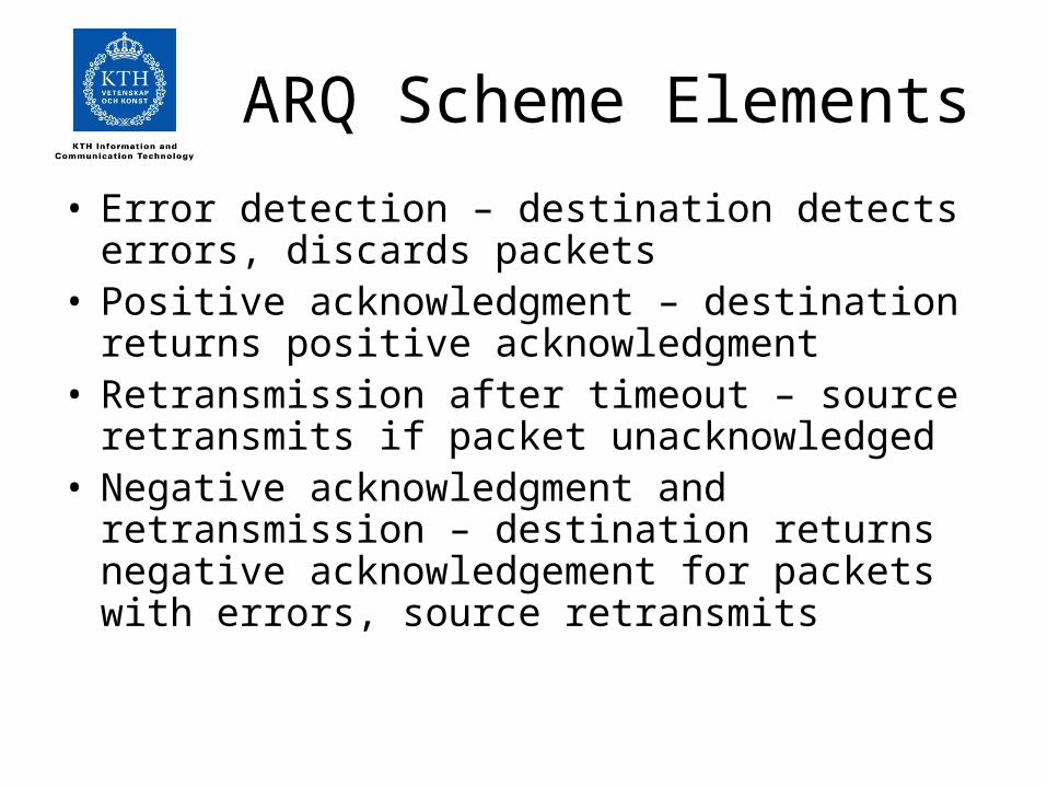
ARQ Scheme Elements• Error detection – destination detects errors, discards
packets• Positive acknowledgment – destination returns
positive acknowledgment• Retransmission after timeout – source retransmits if
packet unacknowledged• Negative acknowledgment and retransmission –
destination returns negative acknowledgement for packets with errors, source retransmits

Bluetooth ARQ

Logical Channels
• Link control (LC)• Link manager (LM)• User asynchronous (UA)• User isochronous (UI)• Use synchronous (US)

Channel Control
• States of operation of a piconet during link establishment and maintenance
• Major states– Standby – default state– Connection – device connected
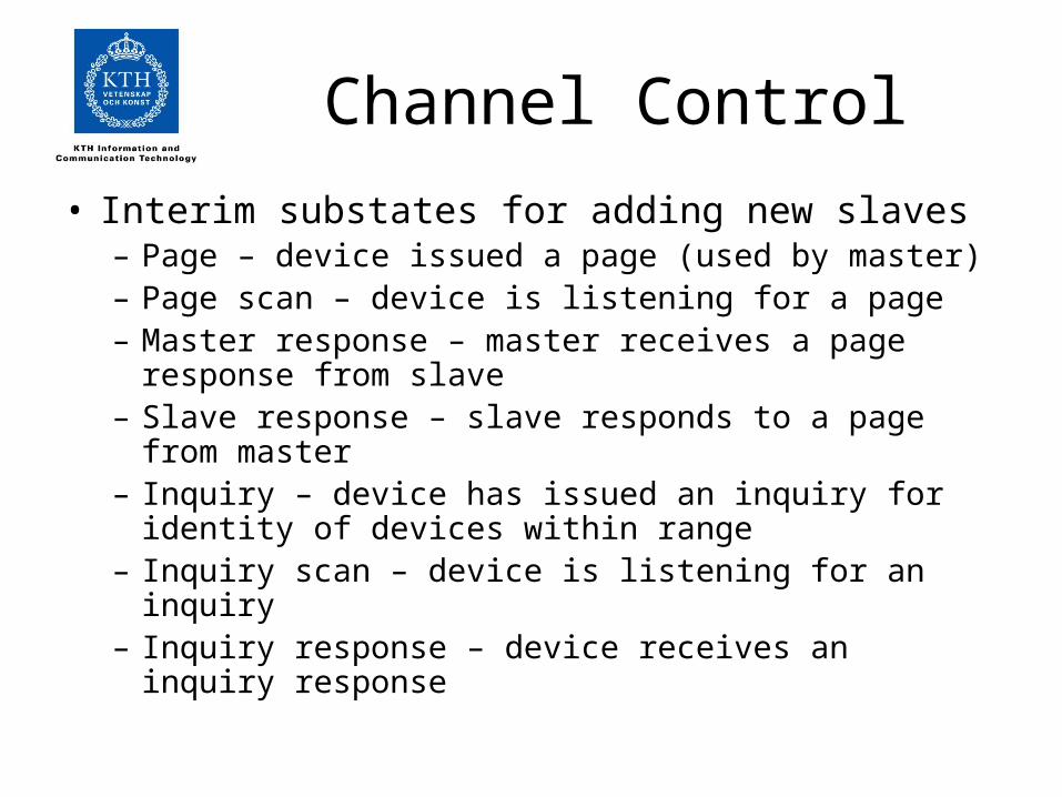
Channel Control• Interim substates for adding new slaves
– Page – device issued a page (used by master)– Page scan – device is listening for a page– Master response – master receives a page response from
slave– Slave response – slave responds to a page from master– Inquiry – device has issued an inquiry for identity of
devices within range– Inquiry scan – device is listening for an inquiry– Inquiry response – device receives an inquiry response

State Transition Diagram

Inquiry Procedure
• Potential master identifies devices in range that wish to participate– Transmits ID packet with inquiry access code (IAC)– Occurs in Inquiry state
• Device receives inquiry– Enter Inquiry Response state– Returns FHS packet with address and timing information– Moves to page scan state

Page Procedure
• Master uses devices address to calculate a page frequency-hopping sequence
• Master pages with ID packet and device access code (DAC) of specific slave
• Slave responds with DAC ID packet• Master responds with its FHS packet• Slave confirms receipt with DAC ID• Slaves moves to Connection state

Slave Connection State Modes
• Active – participates in piconet– Listens, transmits and receives packets
• Sniff – only listens on specified slots• Hold – does not support ACL packets
– Reduced power status– May still participate in SCO exchanges
• Park – does not participate on piconet– Still retained as part of piconet

Bluetooth Audio
• Voice encoding schemes:– Pulse code modulation (PCM) – Continuously variable slope delta (CVSD)
modulation• Choice of scheme made by link manager
– Negotiates most appropriate scheme for application

Bluetooth Link Security
• Elements:– Authentication – verify claimed identity– Encryption – privacy– Key management and usage
• Security algorithm parameters:– Unit address– Secret authentication key– Secret privacy key– Random number

LMP PDUs
• General response• Security Service
– Authentication– Pairing– Change link key– Change current link key– Encryption

LMP PDUs
• Time/synchronization– Clock offset request– Slot offset information– Timing accuracy information request
• Station capability– LMP version– Supported features

LMP PDUs
• Mode control– Switch master/slave role– Name request– Detach– Hold mode– Sniff mode– Park mode– Power control

LMP PDUs
• Mode control (cont.)– Channel quality-driven change between DM and
DH– Quality of service– Control of multislot packets– Paging scheme– Link supervision

L2CAP• Provides a link-layer protocol between entities with a
number of services• Relies on lower layer for flow and error control• Makes use of ACL links, does not support SCO links• Provides two alternative services to upper-layer
protocols– Connection service– Connection-mode service
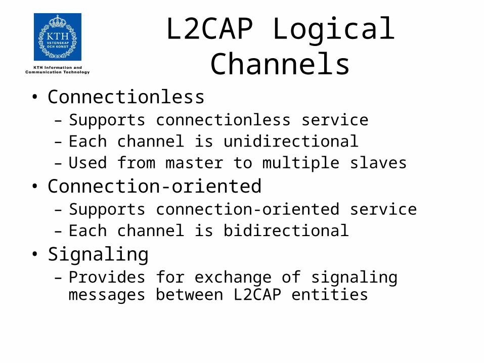
L2CAP Logical Channels• Connectionless
– Supports connectionless service– Each channel is unidirectional– Used from master to multiple slaves
• Connection-oriented– Supports connection-oriented service– Each channel is bidirectional
• Signaling– Provides for exchange of signaling messages between
L2CAP entities

L2CAP Packet Fields for Connectionless Service
• Length – length of information payload, PSM fields• Channel ID – 2, indicating connectionless channel• Protocol/service multiplexer (PSM) – identifies
higher-layer recipient for payload– Not included in connection-oriented packets
• Information payload – higher-layer user data
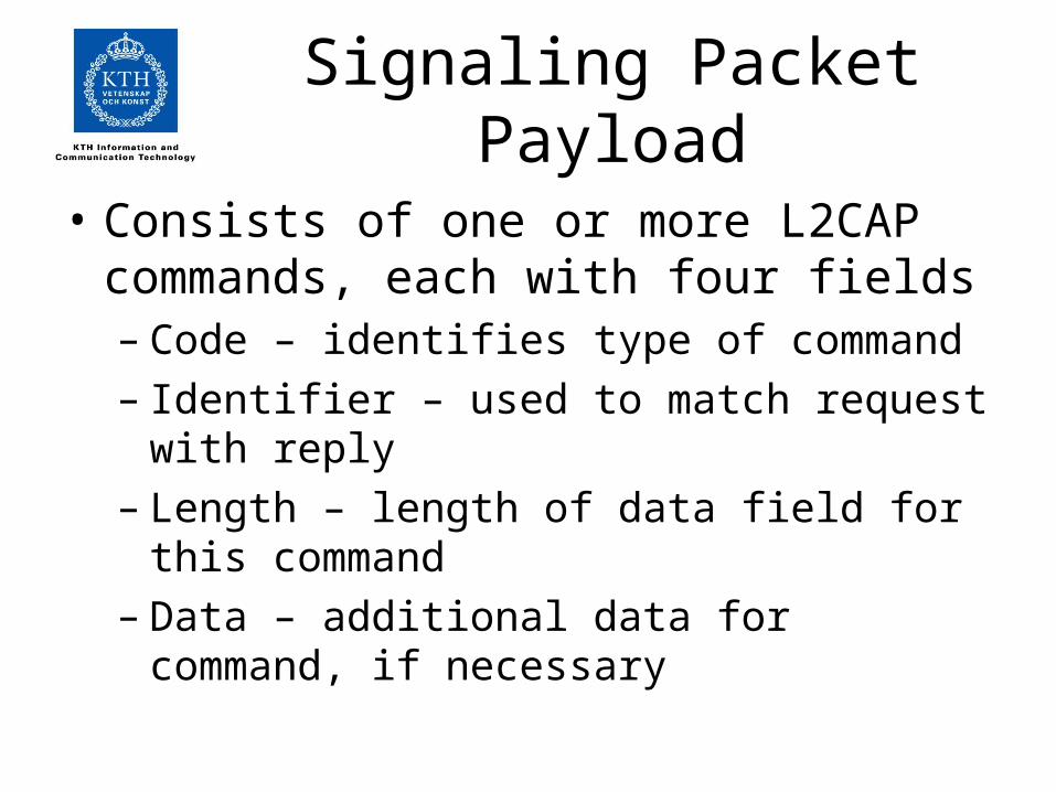
Signaling Packet Payload
• Consists of one or more L2CAP commands, each with four fields– Code – identifies type of command– Identifier – used to match request with reply– Length – length of data field for this command– Data – additional data for command, if necessary

L2CAP Signaling Command Codes
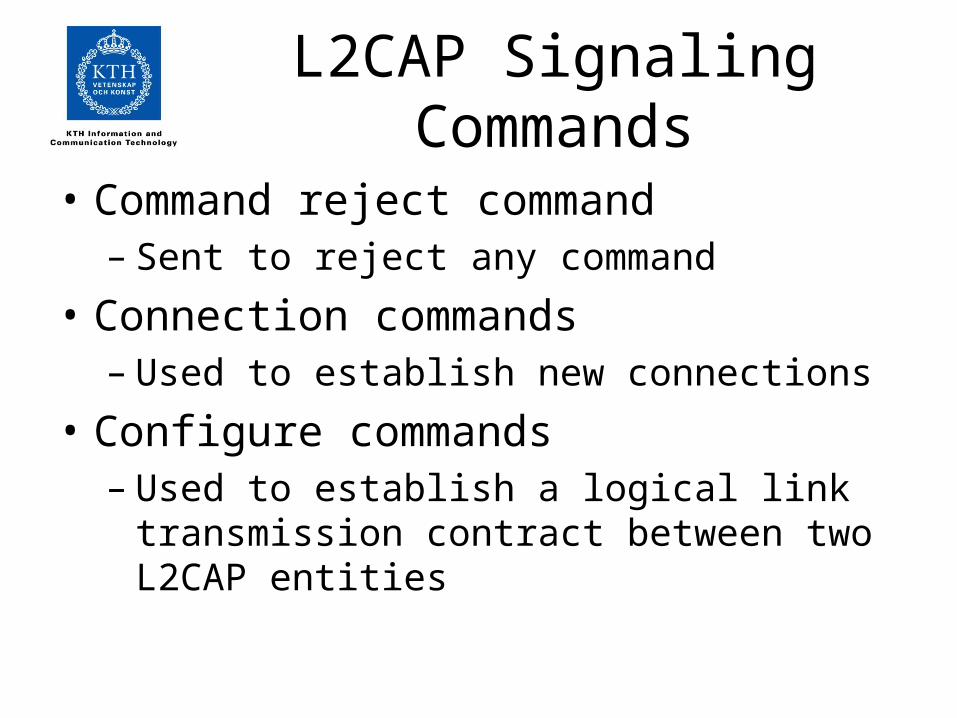
L2CAP Signaling Commands
• Command reject command– Sent to reject any command
• Connection commands – Used to establish new connections
• Configure commands – Used to establish a logical link transmission
contract between two L2CAP entities

L2CAP Signaling Commands
• Disconnection commands – Used to terminate logical channel
• Echo commands– Used to solicit response from remote L2CAP entity
• Information commands– Used to solicit implementation-specific
information from remote L2CAP entity

Flow Specification Parameters
• Service type• Token rate (bytes/second)• Token bucket size (bytes)• Peak bandwidth (bytes/second)• Latency (microseconds)• Delay variation (microseconds)

802.15.4 “Zigbee”• ZigBee is a low-power wireless
communications technology • ZigBee uses the PHY and MAC layers defined
by IEEE 802.15.4, which is the short-distance wireless communication standard for 2.4 GHz band.
• 250 kbit/s• Regional operation on 915 MHz (Americas)
and 868 MHz (Europe)• 20-40 kbit/s

Zigbee Features
• Low Power – 1 mW output power and 10-20 m range
• Support for power saving and power harvesting• Robust • Mesh Networking • Interoperability • Simple MAC layer• Secure

Applications
• Industrial control• Monitoring• Smart badges• Interconnections of environmental sensors• Remote controls

802.15.3
• WPAN Higher rate alternate PHY task group• 110 Mbit/s or greater

802.15.2
• Looks into how to co-exist WLAN and WPAN networks using the same 2.4 GHz frequency band

Trellis Coded Modulation


![{Slides} Job+ Presentation Slides [MKS-40]](https://img.pdfslide.us/doc/110x75/58f058861a28ab96248b45f5/slides-job-presentation-slides-mks-40.jpg)