Embed Size (px)
Citation preview
05/12/2016
1
Energoil
Consulting
Liquefaction Processes
Lecture 14
LNG Alternatives
Slide 1© Dr. Richard J Barnes 2015
Energoil
Consulting
Liquefaction Processes
Compressed
Natural Gas
Slide 2© Dr. Richard J Barnes 2015
05/12/2016
2
Energoil
ConsultingCompressed Natural Gas
• CNG avoids the expense of liquefaction, but does not achieve the same volume reduction.
• Limit of storage pressure is about 240 bar (3,600 psig).
• Reduction is about 1/240 compared with 1/600 for LNG.
• Storage developed to fit on conventional ships.
Slide 3© Dr. Richard J Barnes 2015
Energoil
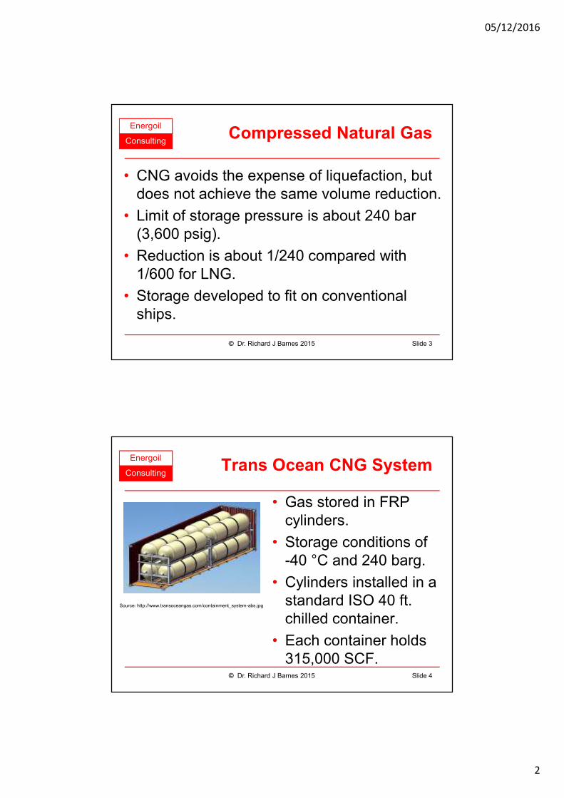
ConsultingTrans Ocean CNG System
• Gas stored in FRP cylinders.
• Storage conditions of -40 °C and 240 barg.
• Cylinders installed in a standard ISO 40 ft. chilled container.
• Each container holds 315,000 SCF.
Slide 4© Dr. Richard J Barnes 2015
Source: http://www.transoceangas.com/containment_system-abs.jpg
05/12/2016
3
Energoil
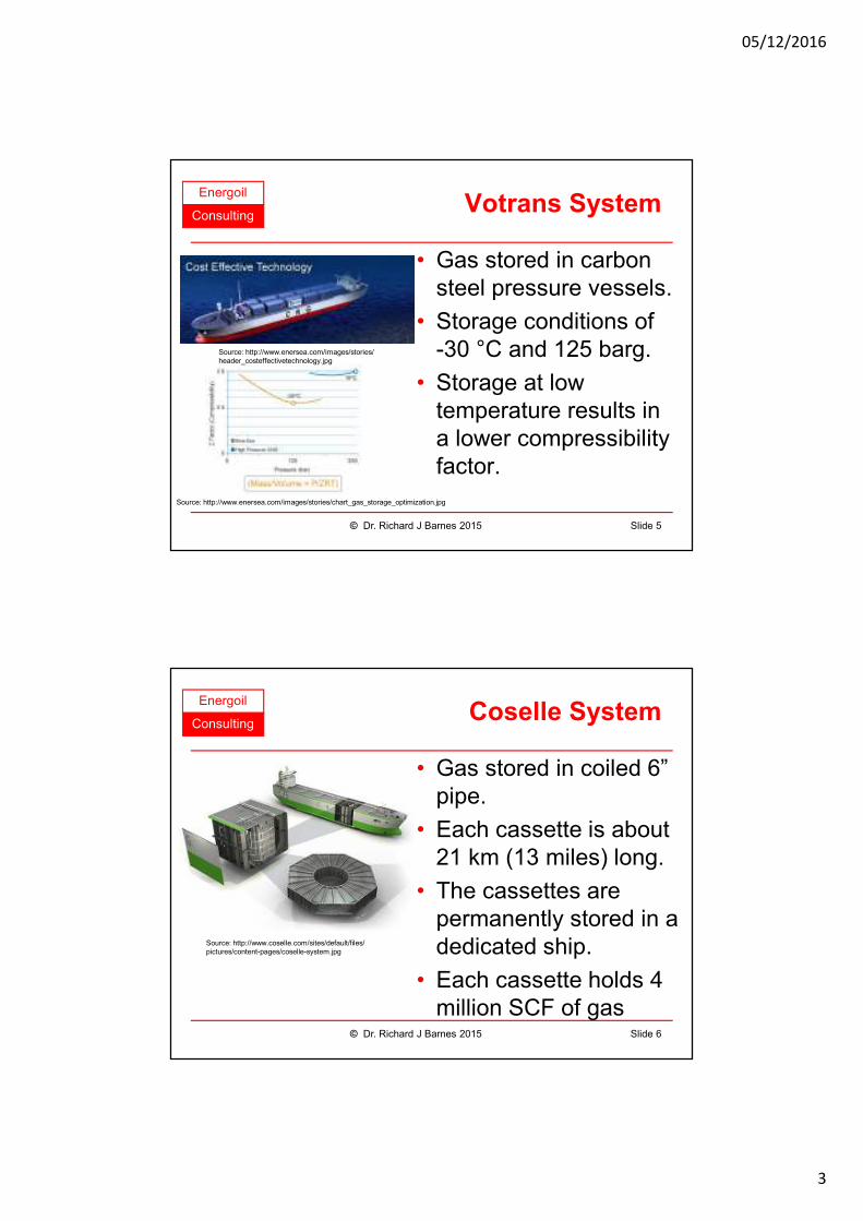
ConsultingVotrans System
• Gas stored in carbon steel pressure vessels.
• Storage conditions of -30 °C and 125 barg.
• Storage at low temperature results in a lower compressibility factor.
Slide 5© Dr. Richard J Barnes 2015
Source: http://www.enersea.com/images/stories/chart_gas_storage_optimization.jpg
Source: http://www.enersea.com/images/stories/header_costeffectivetechnology.jpg
Energoil
ConsultingCoselle System
• Gas stored in coiled 6” pipe.
• Each cassette is about 21 km (13 miles) long.
• The cassettes are permanently stored in a dedicated ship.
• Each cassette holds 4 million SCF of gas
Slide 6© Dr. Richard J Barnes 2015
Source: http://www.coselle.com/sites/default/files/pictures/content-pages/coselle-system.jpg

05/12/2016
4
Energoil
Consulting
Liquefaction Processes
Pipeline Natural
Gas
Slide 7© Dr. Richard J Barnes 2015
Energoil
Consulting
Liquefaction Processes
Slide 8© Dr. Richard J Barnes 2015
Source: http://iis-db.stanford.edu/evnts/3917/jensen_slides_rev.pdf
Natural Gas Transport
05/12/2016
5
Energoil
Consulting
Liquefaction Processes
Gas To Liquids
Slide 9© Dr. Richard J Barnes 2015
Energoil
ConsultingWhat is GTL?
• GTL is Gas to Liquids conversion technology.
• Methane is converted to liquid hydrocarbons.
• Technology is potentially useful for transporting gas over long distances.
• Big research effort over the last 10 - 20 years.
Slide 10© Dr. Richard J Barnes 2015
05/12/2016
6
Energoil
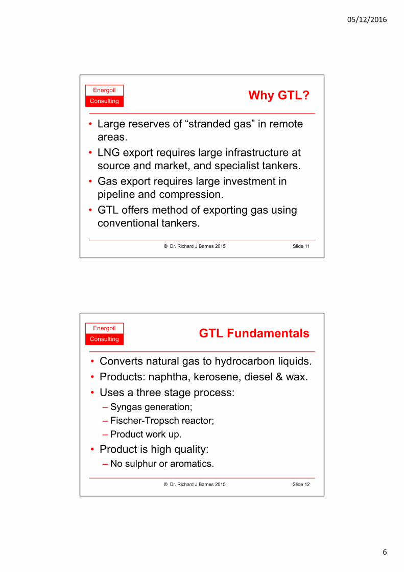
ConsultingWhy GTL?
• Large reserves of “stranded gas” in remote areas.
• LNG export requires large infrastructure at source and market, and specialist tankers.
• Gas export requires large investment in pipeline and compression.
• GTL offers method of exporting gas using conventional tankers.
Slide 11© Dr. Richard J Barnes 2015
Energoil
ConsultingGTL Fundamentals
• Converts natural gas to hydrocarbon liquids.
• Products: naphtha, kerosene, diesel & wax.
• Uses a three stage process:
– Syngas generation;
– Fischer-Tropsch reactor;
– Product work up.
• Product is high quality:
– No sulphur or aromatics.
Slide 12© Dr. Richard J Barnes 2015
05/12/2016
7
Energoil
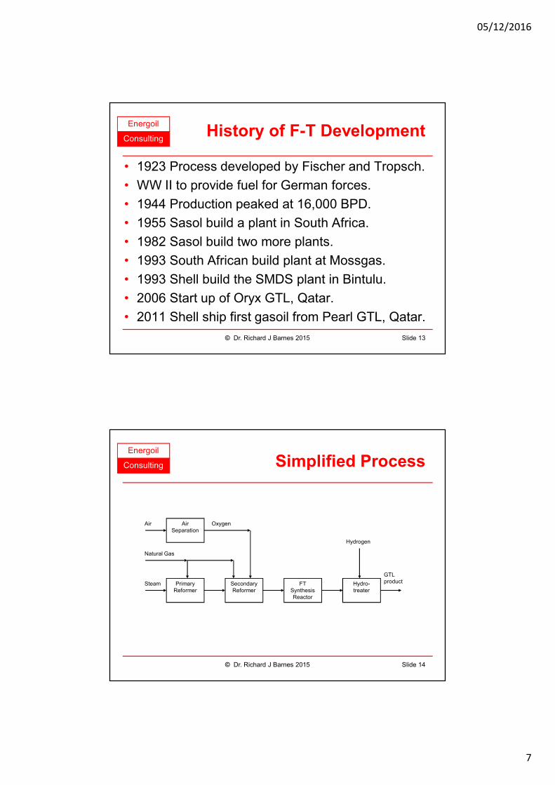
ConsultingHistory of F-T Development
• 1923 Process developed by Fischer and Tropsch.
• WW II to provide fuel for German forces.
• 1944 Production peaked at 16,000 BPD.
• 1955 Sasol build a plant in South Africa.
• 1982 Sasol build two more plants.
• 1993 South African build plant at Mossgas.
• 1993 Shell build the SMDS plant in Bintulu.
• 2006 Start up of Oryx GTL, Qatar.
• 2011 Shell ship first gasoil from Pearl GTL, Qatar.
Slide 13© Dr. Richard J Barnes 2015
Energoil
Consulting Simplified Process
Slide 14© Dr. Richard J Barnes 2015
GTL product
Hydrogen
Oxygen
Natural Gas
Steam
Air Air Separation
Primary Reformer
Secondary Reformer
FT Synthesis Reactor
Hydro-treater
05/12/2016
8
Energoil
Consulting
Liquefaction Processes
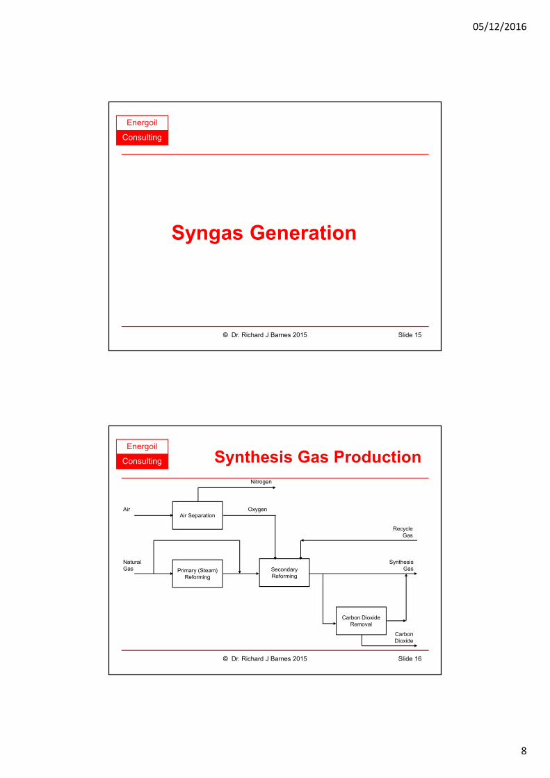
Syngas Generation
Slide 15© Dr. Richard J Barnes 2015
Energoil
Consulting Synthesis Gas Production
Air Separation
Primary (Steam)Reforming
SecondaryReforming
Carbon DioxideRemoval
Air
Nitrogen
Oxygen
NaturalGas
CarbonDioxide
RecycleGas
SynthesisGas
Slide 16© Dr. Richard J Barnes 2015
05/12/2016
9
Energoil
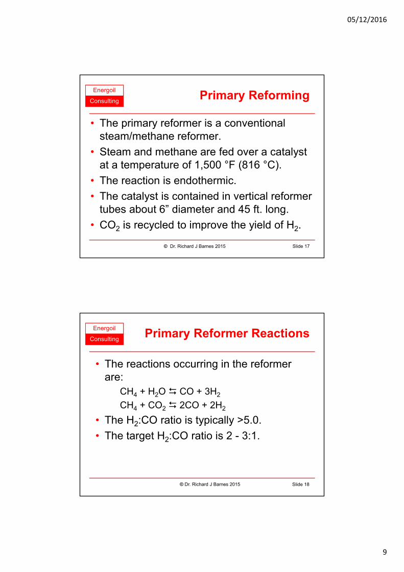
ConsultingPrimary Reforming
• The primary reformer is a conventional steam/methane reformer.
• Steam and methane are fed over a catalyst at a temperature of 1,500 °F (816 °C).
• The reaction is endothermic.
• The catalyst is contained in vertical reformer tubes about 6” diameter and 45 ft. long.
• CO2 is recycled to improve the yield of H2.
Slide 17© Dr. Richard J Barnes 2015
Energoil
Consulting
• The reactions occurring in the reformer are:
CH4 + H2O � CO + 3H2
CH4 + CO2 � 2CO + 2H2
• The H2:CO ratio is typically >5.0.
• The target H2:CO ratio is 2 - 3:1.
© Dr. Richard J Barnes 2015 Slide 18
Primary Reformer Reactions
05/12/2016
10
Energoil
ConsultingSecondary Reforming
• Objective is to make a syngas with a lower H2:CO ratio.
• Methane and oxygen are mixed with steam or CO2 and fed over a catalyst at an outlet temperature of 950 to 1100 °C (1740 to 2000 °F).
• The reaction is exothermic.
• Air can be used instead of oxygen, but dilutes the syngas with N2.
Slide 19© Dr. Richard J Barnes 2015
Energoil
Consulting
• The reactions occurring with CO2 is:
2CH4 + O2 + CO2 � 3H2 + CO + H2O
When steam is used, the reaction is:
4CH4 + O2 + 2H2O � 10H2 + 4CO
• The H2:CO ratio is typically above 2.0.
• The actual H2:CO ratio can be adjusted by variation of the proportion of methane reformed in each reactor and quantities of CO2 and steam fed.
© Dr. Richard J Barnes 2015 Slide 20
Secondary Reformer Reactions
05/12/2016
11
Energoil
Consulting
Liquefaction Processes
Fischer-Tropsch
Reactors
Slide 21© Dr. Richard J Barnes 2015
Energoil
ConsultingF-T Main Reactions
• Main reactions occurring in the F-T reactor are:
Alkenes: nCO + 2nH2 � (CH2)n + nH2O
Alkanes: nCO + (2n+1)H2 � H(CH2)nH + nH2O
Alcohols: nCO + 2nH2 � H(CH2)n OH + (n-1)H2O
Carbonyls: nCO + (2n-1)H2 � (CH2)nO + (n-1)H2O
Carboxylic acids (n>1):
nCO + (2n-2)H2 � (CH2)nO2 + (n-2)H2O
Water gas shift:
CO + H2O � CO2 + H2
Slide 22© Dr. Richard J Barnes 2015
05/12/2016
12
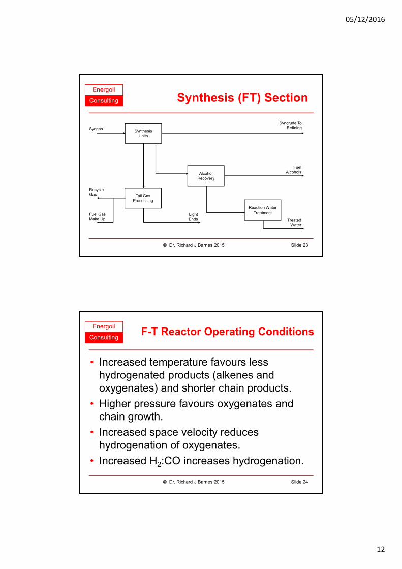
Energoil
Consulting Synthesis (FT) Section
SynthesisUnits
Tail GasProcessing
AlcoholRecovery
Reaction WaterTreatment
Syngas
RecycleGas
TreatedWater
FuelAlcohols
Fuel GasMake Up
Syncrude ToRefining
LightEnds
Slide 23© Dr. Richard J Barnes 2015
Energoil
ConsultingF-T Reactor Operating Conditions
• Increased temperature favours less hydrogenated products (alkenes and oxygenates) and shorter chain products.
• Higher pressure favours oxygenates and chain growth.
• Increased space velocity reduces hydrogenation of oxygenates.
• Increased H2:CO increases hydrogenation.
Slide 24© Dr. Richard J Barnes 2015
05/12/2016
13
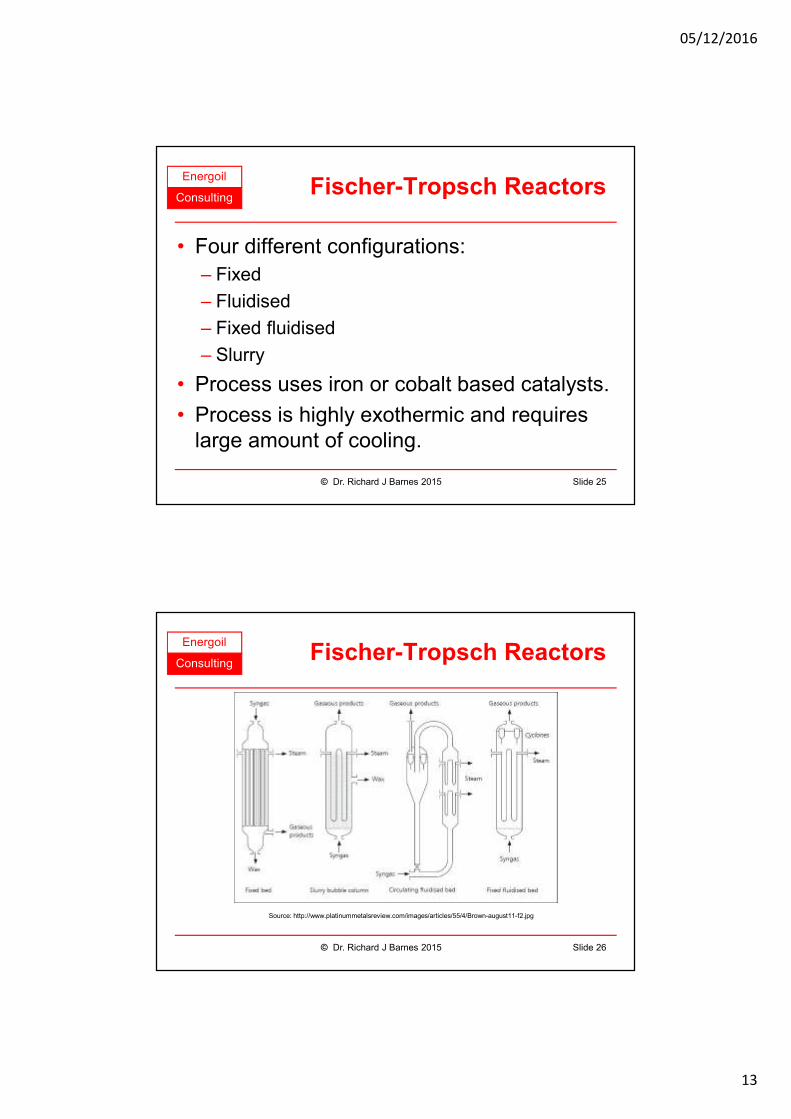
Energoil
ConsultingFischer-Tropsch Reactors
• Four different configurations:
– Fixed
– Fluidised
– Fixed fluidised
– Slurry
• Process uses iron or cobalt based catalysts.
• Process is highly exothermic and requires large amount of cooling.
Slide 25© Dr. Richard J Barnes 2015
Energoil
ConsultingFischer-Tropsch Reactors
Slide 26© Dr. Richard J Barnes 2015
Source: http://www.platinummetalsreview.com/images/articles/55/4/Brown-august11-f2.jpg
05/12/2016
14
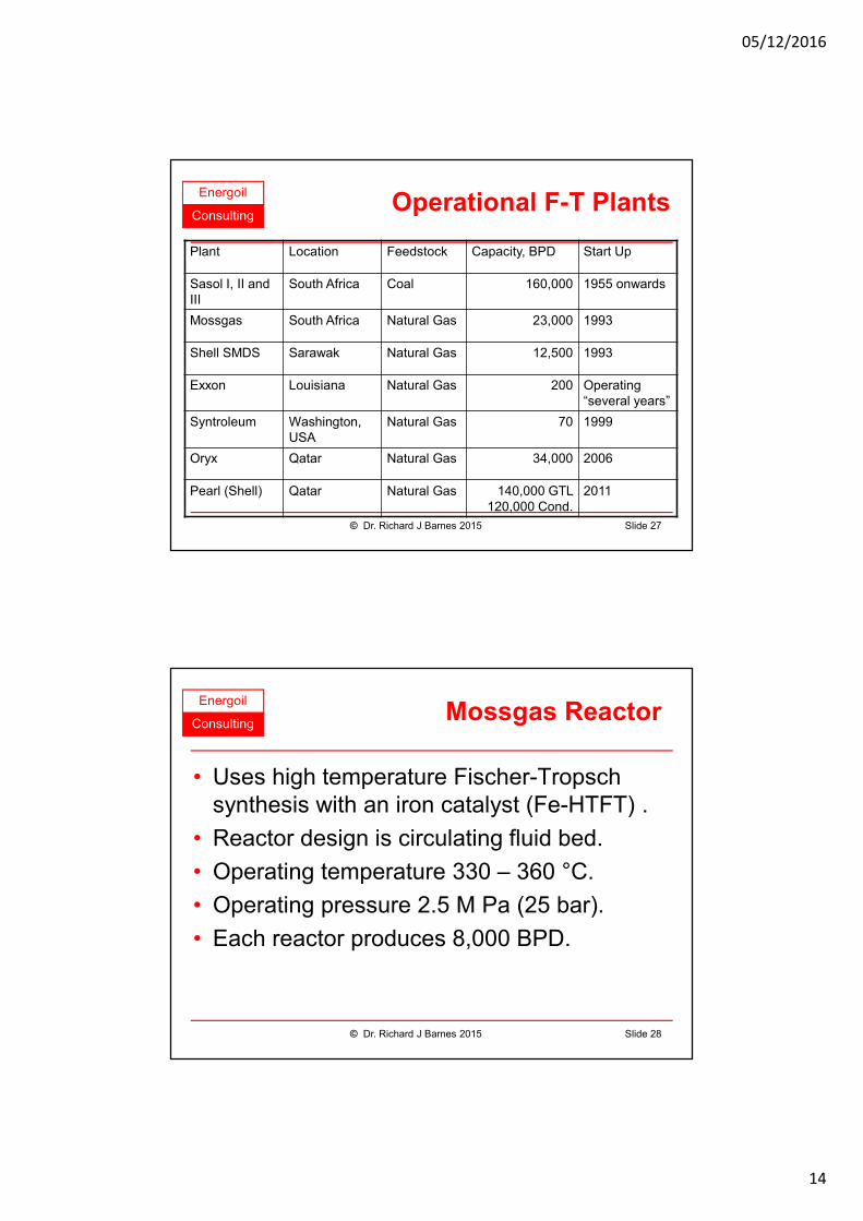
Energoil
ConsultingOperational F-T Plants
Plant Location Feedstock Capacity, BPD Start Up
Sasol I, II and III
South Africa Coal 160,000 1955 onwards
Mossgas South Africa Natural Gas 23,000 1993
Shell SMDS Sarawak Natural Gas 12,500 1993
Exxon Louisiana Natural Gas 200 Operating “several years”
Syntroleum Washington, USA
Natural Gas 70 1999
Oryx Qatar Natural Gas 34,000 2006
Pearl (Shell) Qatar Natural Gas 140,000 GTL 120,000 Cond.
2011
Slide 27© Dr. Richard J Barnes 2015
Energoil
ConsultingMossgas Reactor
• Uses high temperature Fischer-Tropsch synthesis with an iron catalyst (Fe-HTFT) .
• Reactor design is circulating fluid bed.
• Operating temperature 330 – 360 °C.
• Operating pressure 2.5 M Pa (25 bar).
• Each reactor produces 8,000 BPD.
Slide 28© Dr. Richard J Barnes 2015
05/12/2016
15
Energoil
ConsultingSMDS Bintulu
• Low temperature Fischer-Tropsch synthesis with a cobalt catalyst (Co-LTFT).
• Reactor design is multi-tubular fixed bed.
• Operating temperature 220 °C.
• Operating pressure 2.5 M Pa (25 bar).
• Four reactors installed at Bintulu.
• Each reactor produces 3,000 BPD.
• Each reactor contains about 26,000 tubes.
Slide 29© Dr. Richard J Barnes 2015
Energoil
ConsultingPearl GTL Facility
• Scaled up version of Shell Bintulu.
• Two 70,000 BPD trains.
• Each train divided into four modular sections.
• Scale up factors:
– Air separation units, 1.13, one unit per train;
– Partial oxidation reformers, 3.5;
– Multitubular fixed bed F-T reactors, 1.12, six reactors per train.
Slide 30© Dr. Richard J Barnes 2015
05/12/2016
16
Energoil
ConsultingOryx GTL Facility
• Designed for 34,000 BPD trains.
• Capacity initially limited due to catalyst fines clogging downstream equipment.
• Two slurry bed reactors, each 2,100 tons.
• Operating temperature 230 °C.
• Operating pressure 2.5 M Pa (25 bar).
• Catalyst is Co/Pt/Al2O3 LTFT.
Slide 31© Dr. Richard J Barnes 2015
Energoil
Consulting
Liquefaction Processes
Product Work-up
Slide 32© Dr. Richard J Barnes 2015
05/12/2016
17
Energoil
ConsultingProduct Work Up
• F-T product may require further processing dependent on:
– Upstream process (F-T reactor conditions);
– Product market.
• Hydrotreaters can be used to:
– Hydrogenate olefins to paraffins;
– Break long chain waxy hydrocarbons.
Slide 33© Dr. Richard J Barnes 2015
Energoil
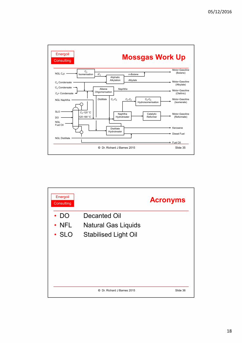
ConsultingMossgas Refining
• F-T product processed with the NGL extracted from the feed gas.
• Light oil feed is distilled under slight vacuum.
• Products are gasoline, kerosene, diesel fuel and fuel oil.
Schematic overleaf after:
Arno de Klerk, Fischer-Tropsch Refining
Slide 34© Dr. Richard J Barnes 2015
05/12/2016
18
Energoil
ConsultingMossgas Work Up
Slide 35© Dr. Richard J Barnes 2015
Fuel Oil
C4
Isomerisation
NaphthaHydrotreater
C5-C6
Hydroisomerisation
CatalyticReformer
DistillateHydrotreater
AliphaticAlkylation
AlkeneOligomerisation
Motor-Gasoline(Butane)
Motor-Gasoline(Alkylate)
Motor-Gasoline(Olefinic)
Motor-Gasoline(Isomerate)
Motor-Gasoline(Reformate)
Kerosene
Diesel Fuel
NGL C4s
C4 Condensate
C3 Condensate
C5+ Condensate
SLO
DO
NGLFuel Oil
NGL Naphtha
iC4 n-Butane
Alkylate
Naphtha
Distillate C5-C6 C5-C6
120-180 °C
C5-120 °C
NGL Distillate
Energoil
ConsultingAcronyms
• DO Decanted Oil
• NFL Natural Gas Liquids
• SLO Stabilised Light Oil
Slide 36© Dr. Richard J Barnes 2015
05/12/2016
19
Energoil
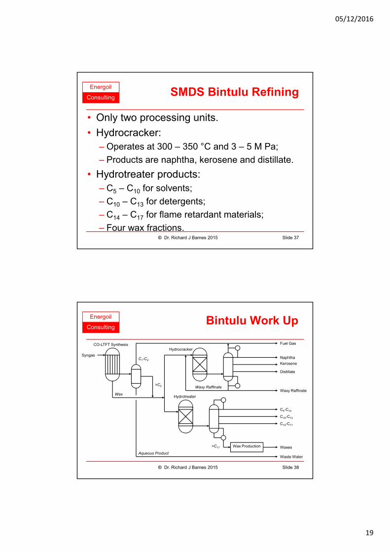
ConsultingSMDS Bintulu Refining
• Only two processing units.
• Hydrocracker:
– Operates at 300 – 350 °C and 3 – 5 M Pa;
– Products are naphtha, kerosene and distillate.
• Hydrotreater products:
– C5 – C10 for solvents;
– C10 – C13 for detergents;
– C14 – C17 for flame retardant materials;
– Four wax fractions.Slide 37© Dr. Richard J Barnes 2015
Energoil
ConsultingBintulu Work Up
Slide 38© Dr. Richard J Barnes 2015
Wax Production
Fuel Gas
Naphtha
Kerosene
Distillate
Waxy Raffinate
C5-C10
Waxes
C10-C13
C14-C17
Waste Water
>C17
Waxy Raffinate
Hydrocracker
Hydrotreater
>C5
C1-C4
Wax
Aqueous Product
CO-LTFT Synthesis
Syngas
05/12/2016
20
Energoil
ConsultingPearl Refining
• Product slate similar to Shell Bintulu.
• SMDS process produces final products and blending materials.
• Distillation only takes place after hydrocracking or hydrotreating to avoid boiling point broadening.
• Tight cuts between product carbon numbers.
Slide 39© Dr. Richard J Barnes 2015
Energoil
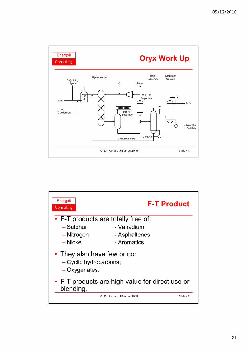
ConsultingOryx Refining
• Single hydrocracker conversion unit.
• Only produces intermediate products and LPG.
• Wax and cold condensate mixed to feed the hydrocracker.
• Hydrocracker operates at 350 °C and 7 M Pa.
• Products are naphtha, distillate and LPG.
Slide 40© Dr. Richard J Barnes 2015
05/12/2016
21
Energoil
ConsultingOryx Work Up
Slide 41© Dr. Richard J Barnes 2015
LPG
NaphthaDistillate
Wax
ColdCondensate
Sulphiding
Agent H2 Purge
HydrocrackerStabiliserColumn
MainFractionator
Hot HPSeparator
Cold HPSeparator
Bottom Recycle>360 °C
Energoil
ConsultingF-T Product
• F-T products are totally free of:– Sulphur - Vanadium
– Nitrogen - Asphaltenes
– Nickel - Aromatics
• They also have few or no:– Cyclic hydrocarbons;
– Oxygenates.
• F-T products are high value for direct use or blending.
Slide 42© Dr. Richard J Barnes 2015
05/12/2016
22
Energoil
ConsultingMain Technology Holders
• BP Amoco (UK and USA)
• Exxon (USA)
• Rentech (USA)
• Sasol (South Africa)
• Shell (UK and Netherlands)
• Syntroleum (USA)
Slide 43© Dr. Richard J Barnes 2015
Energoil
ConsultingEconomics of GTL
• Claimed to be economic against crude oil.
• Integration to use waste heat or tail gas.
• Generates large quantities of waste heat.
• Also produces large quantities of water.
• Technology offers opportunity to develop “stranded” gas.
• Contracting strategy more flexible than LNG.
• High quality GTL fuel attracts a premium.
Slide 44© Dr. Richard J Barnes 2015
05/12/2016
23
Energoil
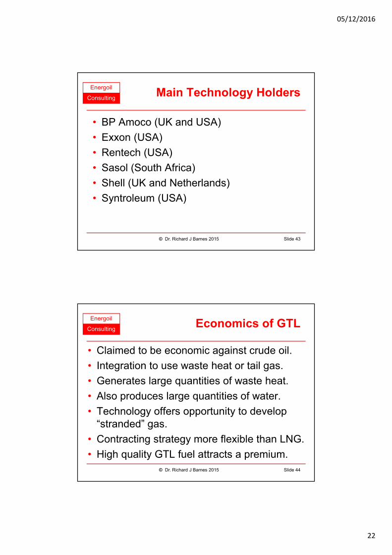
ConsultingSasol Mossgas
• Sasal GTL plant at Mossel Bay, South Africa.
Source: http://www.petroleum-economist.com/images/46/10195/LNGvsGTL_pic.gif
Slide 45© Dr. Richard J Barnes 2015
Energoil
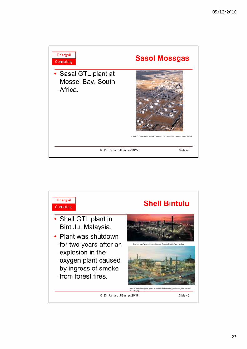
ConsultingShell Bintulu
• Shell GTL plant in Bintulu, Malaysia.
• Plant was shutdown for two years after an explosion in the oxygen plant caused by ingress of smoke from forest fires.
Source: http://www.booklanddirect.com/images/BintuluPlant1-sm.jpg
Source: http://www.jgc.co.jp/en/02bisdmn/05cleanenergy_power/images/02-02-05-00-002-1.jpg
Slide 46© Dr. Richard J Barnes 2015
05/12/2016
24
Energoil
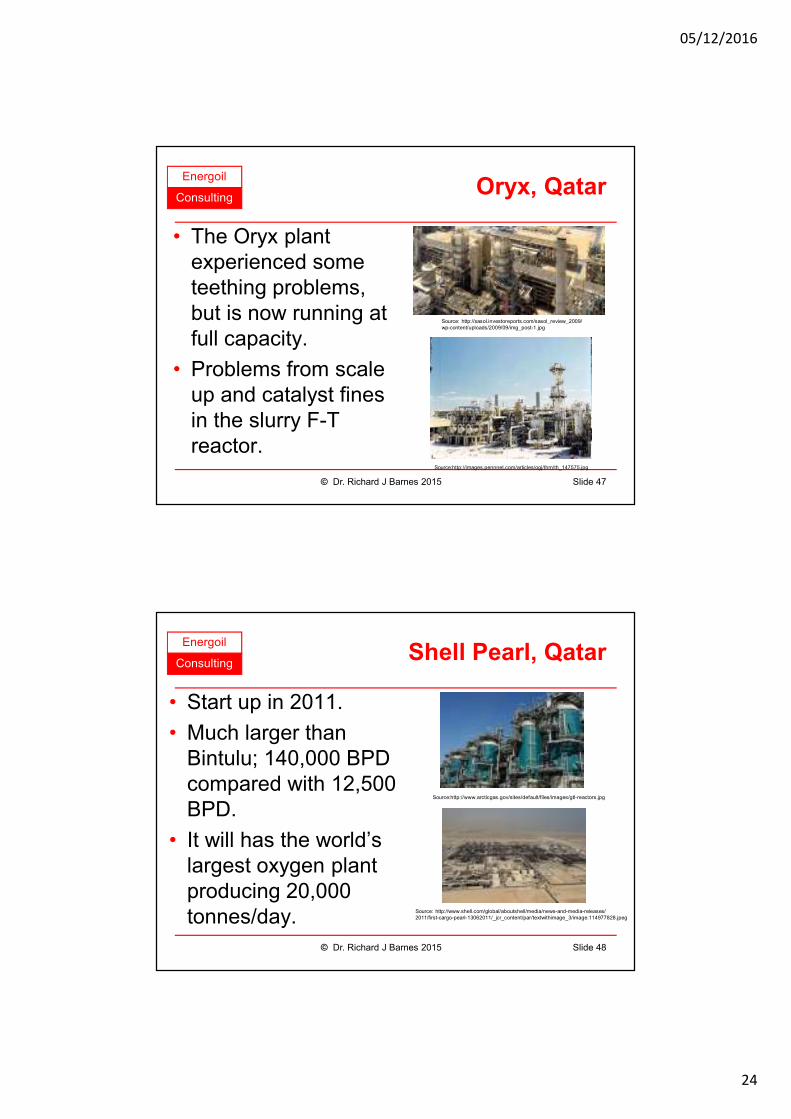
ConsultingOryx, Qatar
• The Oryx plant experienced some teething problems, but is now running at full capacity.
• Problems from scale up and catalyst fines in the slurry F-T reactor.
Source: http://sasol.investoreports.com/sasol_review_2009/wp-content/uploads/2009/09/img_post-1.jpg
Source:http://images.pennnet.com/articles/ogj/thm/th_147575.jpg
Slide 47© Dr. Richard J Barnes 2015
Energoil
ConsultingShell Pearl, Qatar
• Start up in 2011.
• Much larger than Bintulu; 140,000 BPD compared with 12,500 BPD.
• It will has the world’s largest oxygen plant producing 20,000 tonnes/day.
Source:http://www.arcticgas.gov/sites/default/files/images/gtl-reactors.jpg
Source: http://www.shell.com/global/aboutshell/media/news-and-media-releases/2011/first-cargo-pearl-13062011/_jcr_content/par/textwithimage_3/image.114977828.jpeg
Slide 48© Dr. Richard J Barnes 2015
05/12/2016
25
Energoil
ConsultingGTL Capital Cost
• CAPEX $20,000 to 30,000 / bbl capacity.
• 30,000 BPD plant costs $600 - 900 million.
• Only economic above 30,000 BPD capacity.
• Syntroleum claim economic at 2,500 BPD.
• Cost breakdown:
– Syngas production 55%
– FT reaction 35%
– Product upgrading 10%
• Oryx estimated cost $950 million, $28,000/bbl.
• Pearl estimated cost is $6 billion, $23,000/bbl.Slide 49© Dr. Richard J Barnes 2015
Energoil
ConsultingFeedstock
• Free of sulphur compounds
• Limited inerts (CO2, N2, etc).
• Feed gas consumption 8,000 to 10,000 SCF / bbl.
• Oxygen consumption 0.25 tonne / bbl.
Slide 50© Dr. Richard J Barnes 2015
05/12/2016
26
Energoil
ConsultingThe Future
• 93 gasfields with reserves exceeding 5 TCF.
• Most of these are “stranded”, that is have no infrastructure.
• All GTL plants require significant investment, typically $1 billion or more.
• The economic size of plants is decreasing.
• Shell is considering building in Trinidad, Iran and Egypt.
Slide 51© Dr. Richard J Barnes 2015
Energoil
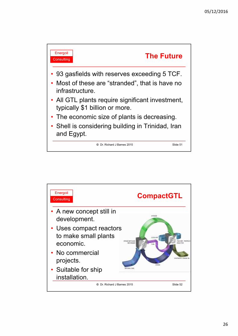
ConsultingCompactGTL
Slide 52
• A new concept still in development.
• Uses compact reactors to make small plants economic.
• No commercial projects.
• Suitable for ship installation.
© Dr. Richard J Barnes 2015
05/12/2016
27
Energoil
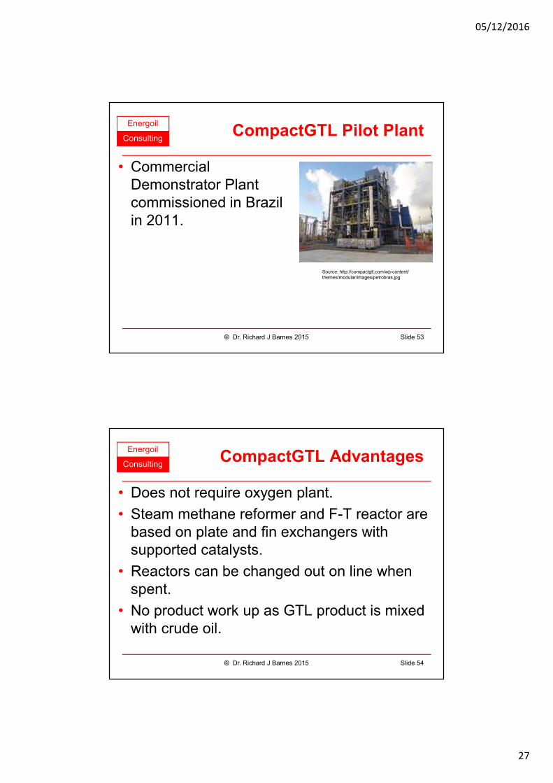
ConsultingCompactGTL Pilot Plant
Slide 53
• Commercial Demonstrator Plant commissioned in Brazil in 2011.
© Dr. Richard J Barnes 2015
Source: http://compactgtl.com/wp-content/themes/modular/images/petrobras.jpg
Energoil
ConsultingCompactGTL Advantages
Slide 54
• Does not require oxygen plant.
• Steam methane reformer and F-T reactor are based on plate and fin exchangers with supported catalysts.
• Reactors can be changed out on line when spent.
• No product work up as GTL product is mixed with crude oil.
© Dr. Richard J Barnes 2015
05/12/2016
28
Energoil
Consulting
Liquefaction Processes
End of Presentation
Slide 55© Dr. Richard J Barnes 2015