Embed Size (px)
DESCRIPTION
Lecture 13 - Optical Attenuation 2 Willner
Citation preview
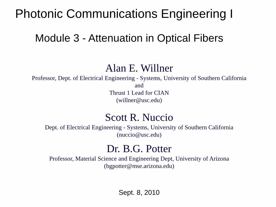
Dr. B.G. PotterProfessor, Material Science and Engineering Dept, University of Arizona
Module 3 - Attenuation in Optical Fibers
Photonic Communications Engineering I
Alan E. WillnerProfessor, Dept. of Electrical Engineering - Systems, University of Southern California
andThrust 1 Lead for CIAN
Scott R. NuccioDept. of Electrical Engineering - Systems, University of Southern California
Sept. 8, 2010

“You can transmit∞ bandwidth
over0 distance !!”
L. Mollenauer, 1990
2
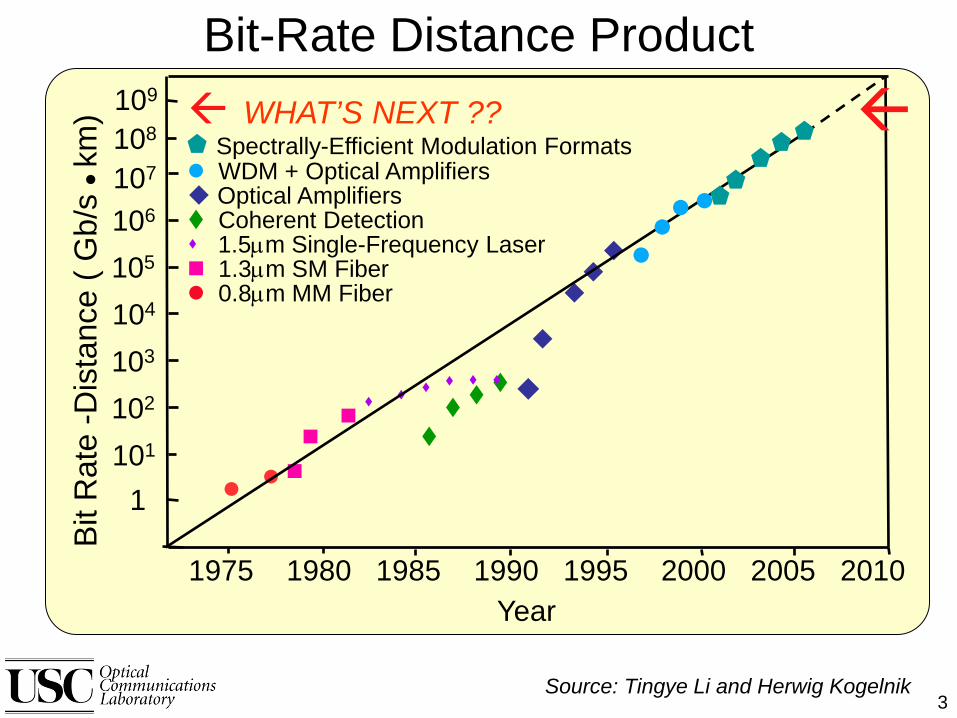
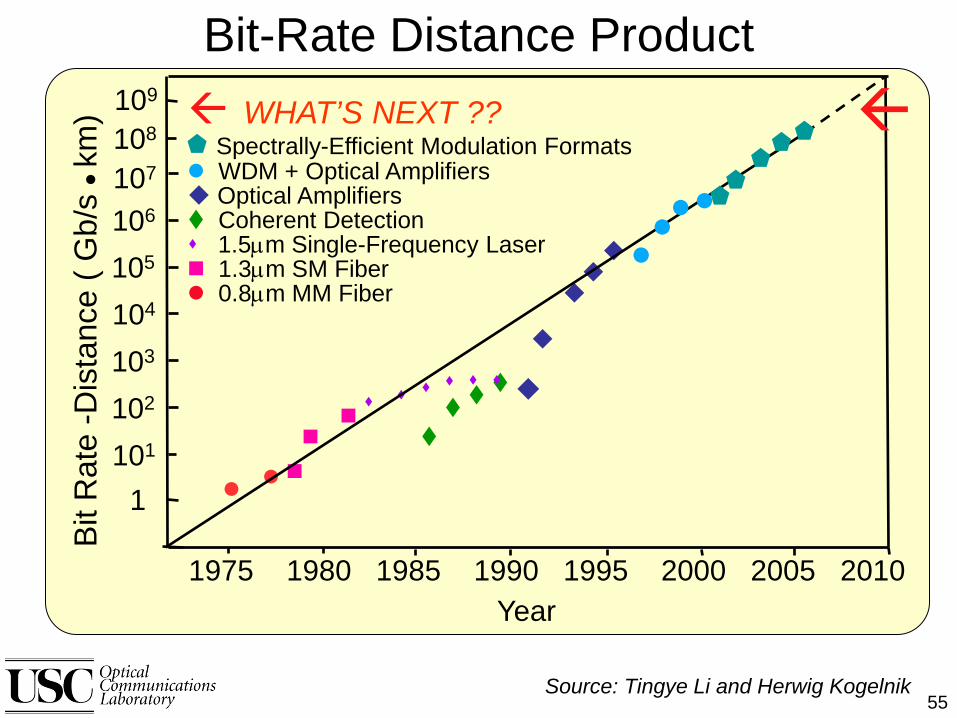
Source: Tingye Li and Herwig Kogelnik
Bit-Rate Distance ProductBi
t Rat
e -D
ista
nce
( Gb/
s
km)
1975 1980 1985 1990 1995 2000 2005 2010Year
1101
102
103
104
105
106
107
108 WHAT’S NEXT ??
Spectrally-Efficient Modulation Formats WDM + Optical Amplifiers Optical Amplifiers Coherent Detection 1.5µm Single-Frequency Laser 1.3µm SM Fiber 0.8µm MM Fiber
109
3

Optical Link Loss Budget
The range of optical Loss over which a Fiber optic Link will operate and meet all specifications. The loss is relative to the Transmitter Output Power and affects the required Receiver input power.
4

The overall optical throughput (transmission) of an optical fiber can be quantified in terms of the input optical power, P(0), and the output power, P(z) observed after light propagates a distance, z, along the fiber length:
ztotalePzP α−= )0()(
)0()(% P
zPT =
αtotal = the total attenuation coefficient (i.e. involving all contributions to attenuation).
%T is the percentage optical power transmission.
Equation 3.1 is referred to as Beer’s Law and shows that transmitted power decreases exponentially with propagation distance through the fiber.
(Equation 3.2)
(Equation 3.1)
and
Optical Loss
5

In an optical fiber transmission context, the attenuation coefficient is often expressed in Base-10 or Logarithmic form:
)km(343.4)()0(log10)dB/km( 1−=
= totaltotal zP
Pz
αα(Equation 3.3)
This final parameter is often referred to as the “fiber loss”.
Optical Loss
6

The propagation of light within a material can be described in terms of a complex refractive index (n*):
)()(* ωκω inn +=
cωκωα 2)( =
(Equation 3.4)
n(ω) = real portion of the refractive index; κ(ω) = extinction coefficient.and:
(Equation 3.5)
α(ω) = absorption coefficient; c = speed of light.
Thus, via equation (3.1), the absorption coefficient contributes directly to the output power observed through its participation in the overall attenuation coefficient, αtotal.
Complex Index of Refraction
7
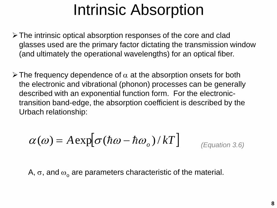
The intrinsic optical absorption responses of the core and clad glasses used are the primary factor dictating the transmission window (and ultimately the operational wavelengths) for an optical fiber.
The frequency dependence of α at the absorption onsets for both the electronic and vibrational (phonon) processes can be generally described with an exponential function form. For the electronic-transition band-edge, the absorption coefficient is described by the Urbach relationship:
[ ]kTA o /)(exp)( ωωσωα −=
A, σ, and ωo are parameters characteristic of the material.
(Equation 3.6)
Intrinsic Absorption
8

Photoabsorption
* Ephoton > Egap : Absorption of light (direct bandgap material)
* Ephoton < Egap : Transparent to light
Incident Photon
Conduction Band
Valence Band
Electron-Hole Pair Created
Incident Photon
Valence Band
Conduction BandTransmitted Photon
+
-
Before After
9
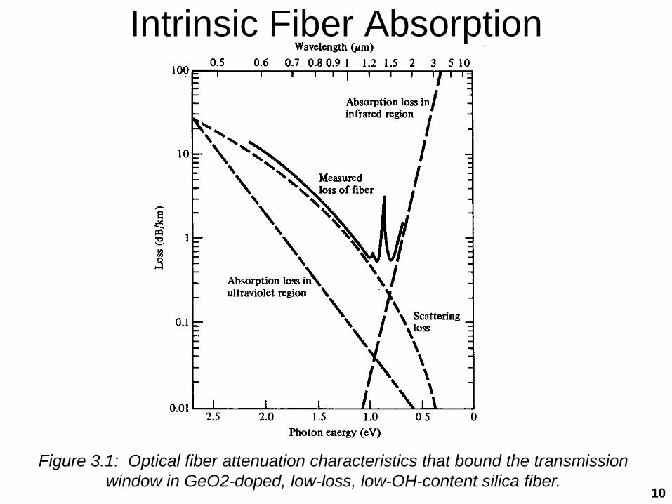
Figure 3.1: Optical fiber attenuation characteristics that bound the transmission window in GeO2-doped, low-loss, low-OH-content silica fiber.
Intrinsic Fiber Absorption
10

http://www.fiberoptics4sale.com/wordpress/optical-fiber-attenuation/
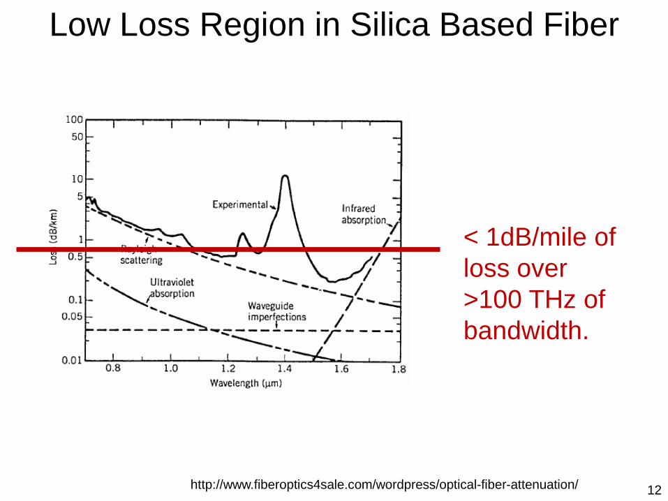
Low Loss Region in Silica Based Fiber
11
http://www.fiberoptics4sale.com/wordpress/optical-fiber-attenuation/
Low Loss Region in Silica Based Fiber
< 1dB/mile of loss over >100 THz of bandwidth.
12
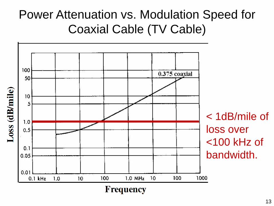
Power Attenuation vs. Modulation Speed for Coaxial Cable (TV Cable)
< 1dB/mile of loss over <100 kHz of bandwidth.
13

Defects in the glass structure (e.g. vacancies, over/under coordinated atoms) and/or dopants and impurities can produce localized absorption states. For silica-based fibers, water (hydroxyls (OH-)) within the glass structure is a common impurity.
Figure 3.2: Absorptive attenuation in silicate fiber.
Extrinsic Fiber Absorption (Water)
14

Figure 3.3: A comparison of the effects of dopants on infrared absorption in silicate fibers.
Extrinsic Fiber Absorption (Glass Dopants)
15
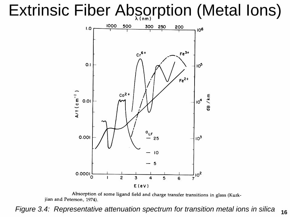
Figure 3.4: Representative attenuation spectrum for transition metal ions in silica
Extrinsic Fiber Absorption (Metal Ions)
16

Modification in the glass structure associated with missing atoms (vacancies) or disturbances in the anticipated bond topology of the glass network also contribute states within the forbidden band.
These states typically result in an extension of absorption into the transparency region (band tail states).
Such defect structures often form as the result of thermal processing atmosphere (e.g. redox conditions) or through the stress-induced structural modification (residual strain) produced during fiber drawing.
Optical Scattering
* Ephoton > Egap : Absorption of light (direct bandgap material)
Incident Photon
Conduction Band
Valence Band
Electron-Hole Pair Created
+
-
17

These defects also lead to the scattering (reflection and refraction) of light as it passes through the fiber
Optical Scattering
http://www.fiberoptics4sale.com/wordpress/optical-fiber-attenuation/
Types of scattering:
• Rayleigh
• Mie
• Brillouin
18
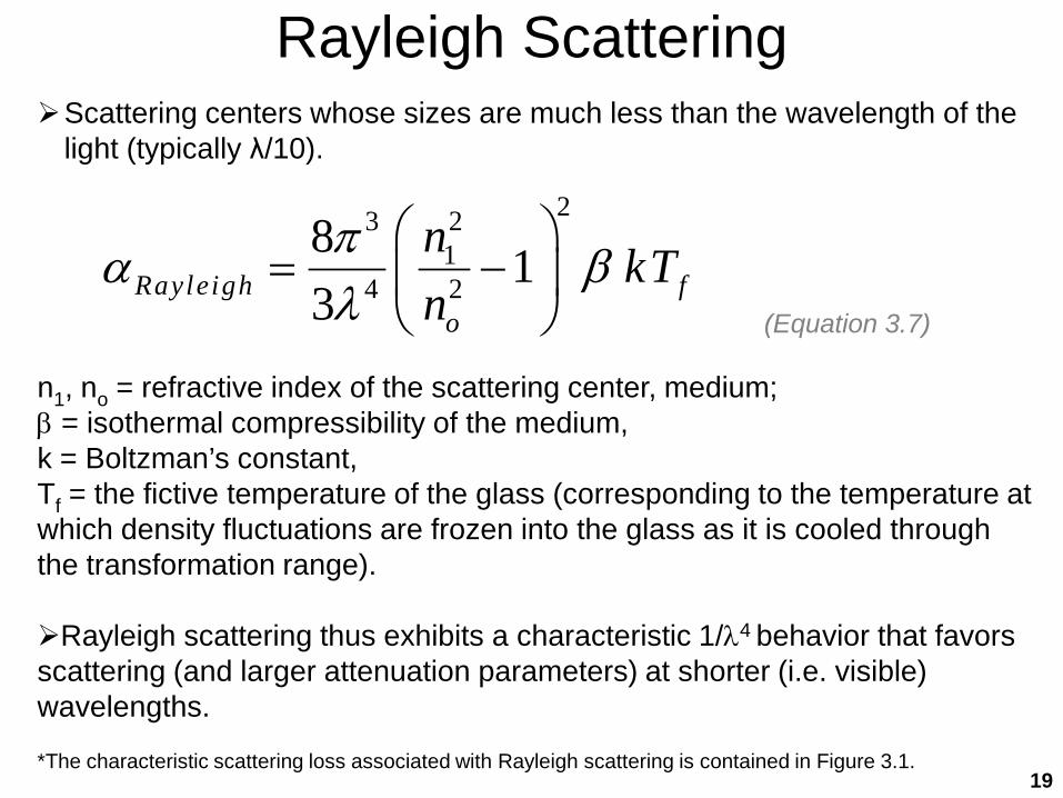
Rayleigh ScatteringScattering centers whose sizes are much less than the wavelength of the
light (typically λ/10).
2231
4 2
8 13Rayleigh f
o
n kTn
πα βλ
= −
n1, no = refractive index of the scattering center, medium; β = isothermal compressibility of the medium, k = Boltzman’s constant, Tf = the fictive temperature of the glass (corresponding to the temperature at which density fluctuations are frozen into the glass as it is cooled through the transformation range).
Rayleigh scattering thus exhibits a characteristic 1/λ4 behavior that favors scattering (and larger attenuation parameters) at shorter (i.e. visible) wavelengths.
*The characteristic scattering loss associated with Rayleigh scattering is contained in Figure 3.1.
(Equation 3.7)
19

Mie ScatteringFor larger scattering centers that approach the wavelength of light, the
scattering light intensity has a greater angular dependence and the process is governed by Mie scattering theory.
For a spherical inclusion with a complex dielectric function given by:
21* εεε i+=
the attenuation parameter associated with Mie scattering from N spheres/unit volume embedded in a medium with a refractive index of no is:
22
21
23
)2(18
εελεπ
α++
=o
oMie n
Nn
Typically fluctuations in density or composition from phase separation in the glass and/or the development of crystallinity.
Further increases in scattering center size results in a largely wavelength-independent scattering attenuation behavior, governed by the absorption and reflection behavior at the interfaces involved.
(Equation 3.8)
(Equation 3.9)
20

Bending LossPropagating modes within an optical fiber can be characterized by an
electric field distribution with maxima inside the fiber core and evanescent fields that extend outside the fiber core into the cladding. Thus, some of the optical energy in the mode is actually propagating in the cladding.
Figure 3.5: Sketch of the fundamental mode filed in a curved optical waveguide. 21
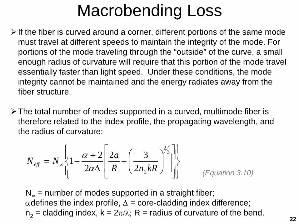
Macrobending Loss If the fiber is curved around a corner, different portions of the same mode
must travel at different speeds to maintain the integrity of the mode. For portions of the mode traveling through the “outside” of the curve, a small enough radius of curvature will require that this portion of the mode travel essentially faster than light speed. Under these conditions, the mode integrity cannot be maintained and the energy radiates away from the fiber structure.
The total number of modes supported in a curved, multimode fiber is therefore related to the index profile, the propagating wavelength, and the radius of curvature:
+
∆+
−= ∞
32
2232
221
kRnRaNNeff α
α
N∞ = number of modes supported in a straight fiber; αdefines the index profile, ∆ = core-cladding index difference; n2 = cladding index, k = 2π/λ; R = radius of curvature of the bend.
(Equation 3.10)
22

Q. Wang, G. Farrell and T. Freir, "Theoretical and experimental investigations of macro-bend Losses for standard single mode fibers", Optics Express, Vol.13, No.12, 4476-4484, 2005.
Q. Wang, G. Farrell, T.Freir, G. Rajan and P. Wang "Low-cost Wavelength Measurement based on a Macrobending Singlemode Fiber", Optics Letters, Vol. 31, No. 12, pp. 1785-1787, 2006.
Macrobending Loss In SMF
23
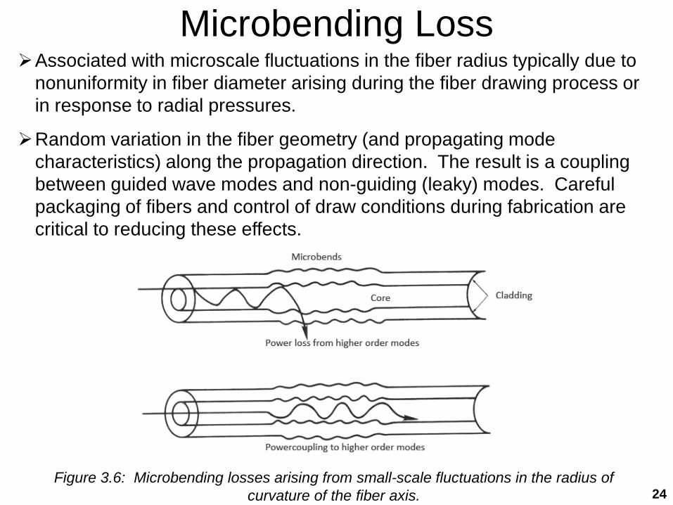
Microbending LossAssociated with microscale fluctuations in the fiber radius typically due to
nonuniformity in fiber diameter arising during the fiber drawing process or in response to radial pressures.
Random variation in the fiber geometry (and propagating mode characteristics) along the propagation direction. The result is a coupling between guided wave modes and non-guiding (leaky) modes. Careful packaging of fibers and control of draw conditions during fabrication are critical to reducing these effects.
Figure 3.6: Microbending losses arising from small-scale fluctuations in the radius of curvature of the fiber axis. 24
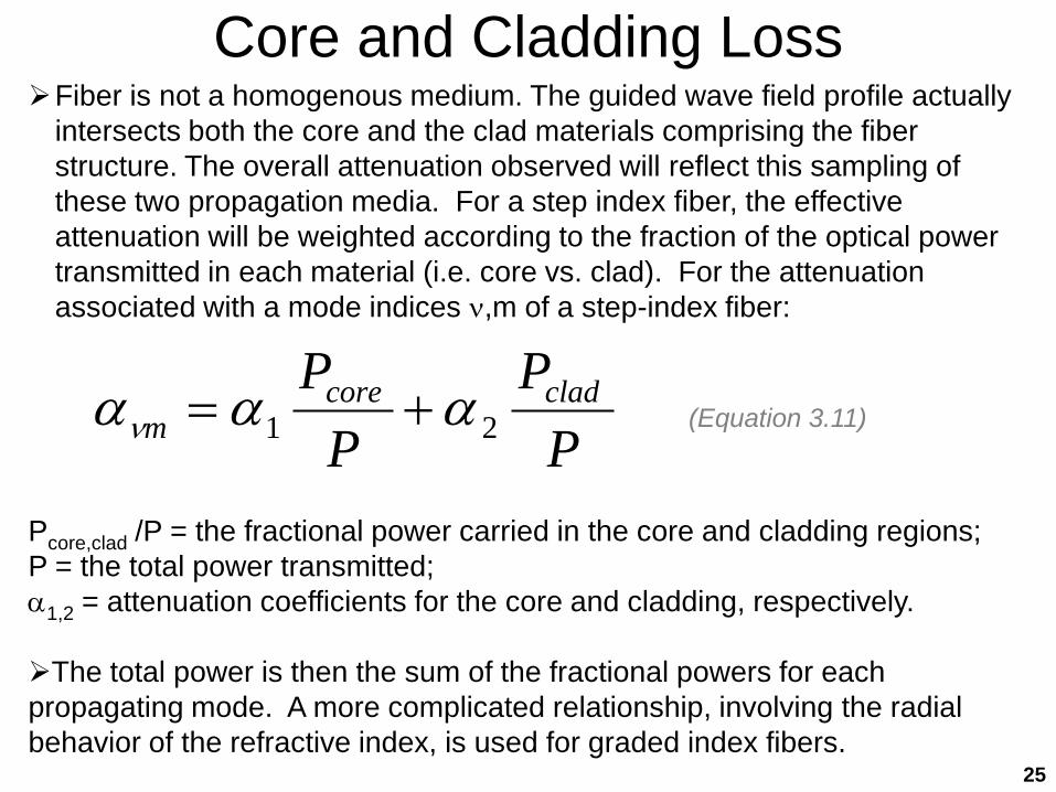
Core and Cladding LossFiber is not a homogenous medium. The guided wave field profile actually
intersects both the core and the clad materials comprising the fiber structure. The overall attenuation observed will reflect this sampling of these two propagation media. For a step index fiber, the effective attenuation will be weighted according to the fraction of the optical power transmitted in each material (i.e. core vs. clad). For the attenuation associated with a mode indices ν,m of a step-index fiber:
PP
PP cladcore
m 21 αααν +=
Pcore,clad /P = the fractional power carried in the core and cladding regions; P = the total power transmitted; α1,2 = attenuation coefficients for the core and cladding, respectively.
The total power is then the sum of the fractional powers for each propagating mode. A more complicated relationship, involving the radial behavior of the refractive index, is used for graded index fibers.
(Equation 3.11)
25
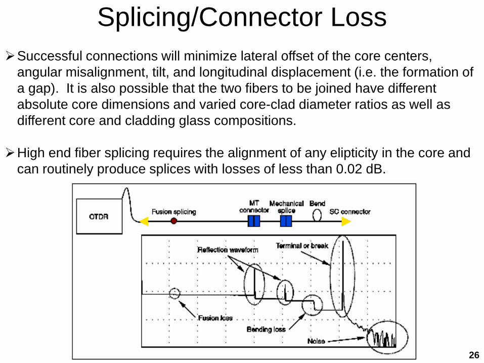
Splicing/Connector LossSuccessful connections will minimize lateral offset of the core centers,
angular misalignment, tilt, and longitudinal displacement (i.e. the formation of a gap). It is also possible that the two fibers to be joined have different absolute core dimensions and varied core-clad diameter ratios as well as different core and cladding glass compositions.
High end fiber splicing requires the alignment of any elipticity in the core and can routinely produce splices with losses of less than 0.02 dB.
26
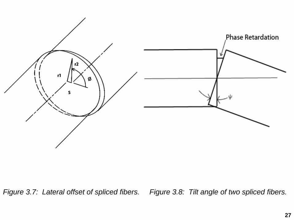
Figure 3.7: Lateral offset of spliced fibers. Figure 3.8: Tilt angle of two spliced fibers.
27

Typical Fiber Connectors
28
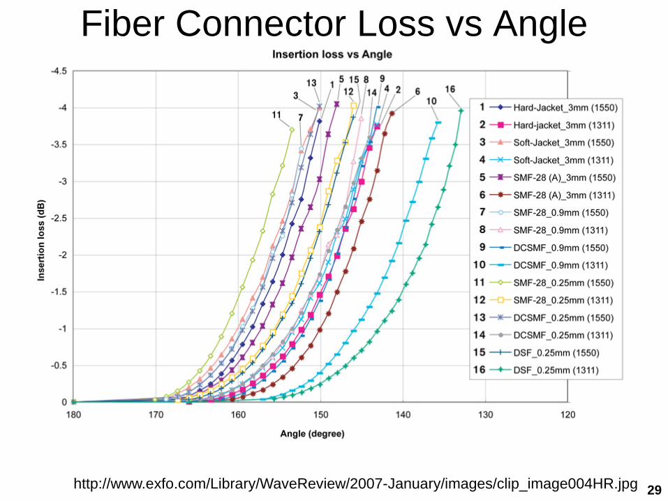
Fiber Connector Loss vs Angle
http://www.exfo.com/Library/WaveReview/2007-January/images/clip_image004HR.jpg 29

Reference Material
“Optical Fiber Telecommunication IV”, Academic Press
“Optical Fiber Communication Systems”, (Artech
House), Kazovsky, Benedetto, Willner
IEEE Photonics Technology Letters
IEEE/OSA J. of Lightwave Technology
Optical Fiber Communications Conference
European Conference on Optical Communications
Lightwave Magazine
30
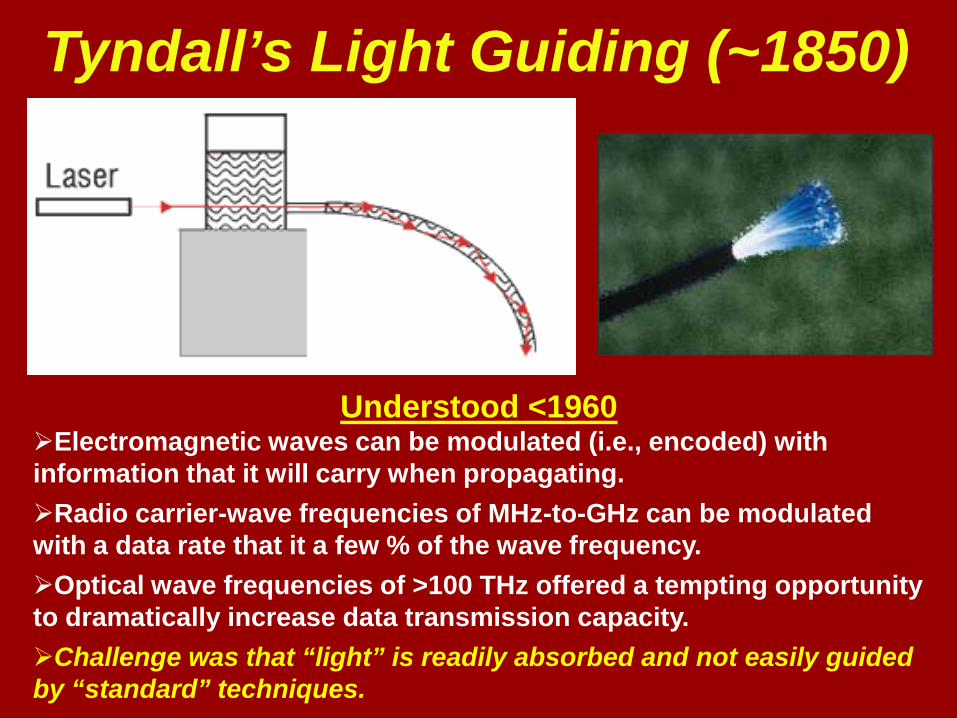
Tyndall’s Light Guiding (~1850)
Understood <1960Electromagnetic waves can be modulated (i.e., encoded) with information that it will carry when propagating.Radio carrier-wave frequencies of MHz-to-GHz can be modulated with a data rate that it a few % of the wave frequency.Optical wave frequencies of >100 THz offered a tempting opportunity to dramatically increase data transmission capacity.Challenge was that “light” is readily absorbed and not easily guided by “standard” techniques.
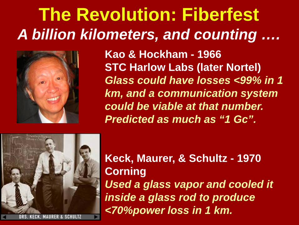
The Revolution: FiberfestA billion kilometers, and counting ….
Kao & Hockham - 1966STC Harlow Labs (later Nortel)Glass could have losses <99% in 1 km, and a communication system could be viable at that number. Predicted as much as “1 Gc”.
Keck, Maurer, & Schultz - 1970CorningUsed a glass vapor and cooled it inside a glass rod to produce <70%power loss in 1 km.

Dr. Kao traveled the world to convince all that his new idea will work! Circa 1968 in Japan.
From Nobel Lecture, Stockholm, 2009

WOCC-TLI
Charles Kao’s Innovation
∙ Charles conceptualized optical fiber communication by proposing glass fibers be used as the transmission medium ─ vision!
∙ He inferred insightfully that silica is the low-loss material of choice for transmission fibers and proceeded to verify his conjecture by sophisticated measurements of bulk silica material samples ─ understanding of fundamental physics!
∙ He participated in the very early work in the field and traveled around the world to spread his “gospel” ─ passion!
Innovation may be defined as the process by which ideas and concepts are created and translated into viable applications
From Tingye Li, 2010

WOCC-TLI
Conceptualization of Optical Fiber Communication
In his seminal paper co-authored with G. A. Hockham in 1966, “Dielectric-fibre surface waveguide for optical frequencies”, Charles Kao proposed clad dielectric fibers as a “new form of communication medium” and considered their electromagnetic properties and physical requirements for information transmission. ─ first concepts and considerations!
They concluded by saying “Thus, compared with existing coaxial-cable and radio systems,this form of waveguide has a larger informationcapacity and possible advantages in basic material cost.” ─ signature of true engineers!
Dielectric-fibre surface waveguides for Optical frequencies
K. C. Kao, Ph.D,, A.M. IEE and G. A. Hockham, B.Sc., Grad. IEE
Synopsis
A dielectric fibre with a refractive index higher than its surrounding region is a form of dielectric waveguide which represents a possible medium for guided transmission of energy at optical frequencies. The particular type of dielectric-fibre waveguide discussed is one with a circular cross-section. The choice of the mode of propagation for a fibre waveguide used for communication purposes is governed by consideration of loss characteristics and information capacity. Dielectric loss, bending loss and radiation loss are discussed, and mode stability, dispersion and power handling are examined with respect to information capacity. Physical-realisation aspects are also discussed. Experimental investigations at both optical and microwave wavelengths are included.
C. K . Kao and G. a. Hockham, (STL), Proc. IEE, Vol., 113, No. 7, July 1966
From Tingye Li, 2010
WOCC-TLI
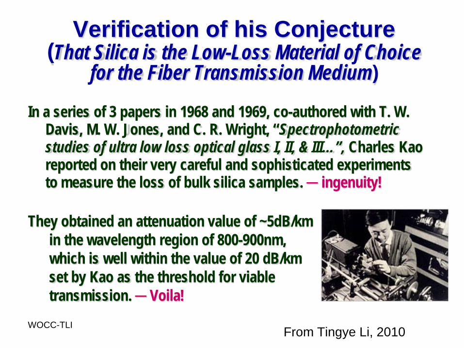
Verification of his Conjecture(That Silica is the Low-Loss Material of Choice
for the Fiber Transmission Medium)
In a series of 3 papers in 1968 and 1969, co-authored with T. W. Davis, M. W. Jones, and C. R. Wright, “Spectrophotometric studies of ultra low loss optical glass I, II, & III…”, Charles Kao reported on their very careful and sophisticated experiments to measure the loss of bulk silica samples. ─ ingenuity!
They obtained an attenuation value of ~5dB/kmin the wavelength region of 800-900nm, which is well within the value of 20 dB/km set by Kao as the threshold for viable transmission. ─ Voila!
From Tingye Li, 2010

37
Coaxial Cable
Fiber
Power Loss at Given Data Modulation Rate for
1 km1 Mbit/s
Fiber vs. Coaxial Cable
~0.4 mm
Thickness
~10 mm
• Fiber is significantly smaller in size than coaxial cable.• The signal power loss in a coaxial cable increases with data modulation rate, whereas the loss in fiber remains relatively constant.
(Human hair ~0.1 mm)
1 Gbit/s
~60% >99.99%
~5% ~5%
38
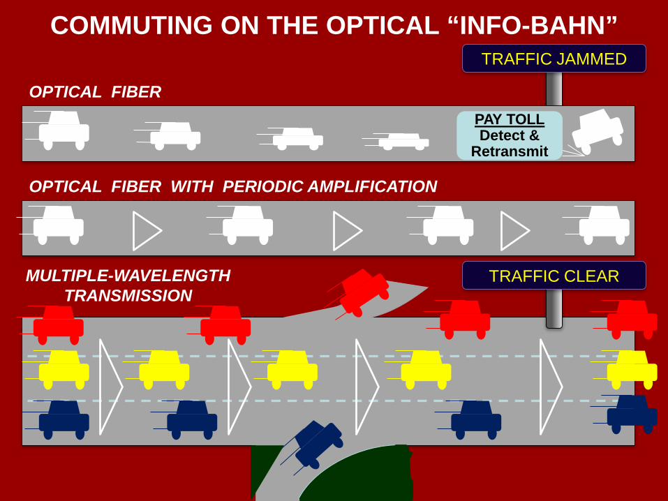
COMMUTING ON THE OPTICAL “INFO-BAHN”TRAFFIC JAMMED
OPTICAL FIBER
OPTICAL FIBER WITH PERIODIC AMPLIFICATION
TRAFFIC CLEARMULTIPLE-WAVELENGTH TRANSMISSION
PAY TOLLDetect &
Retransmit
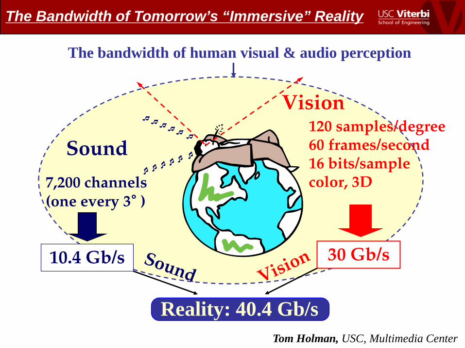
Reality: 40.4 Gb/s
Vision
Sound120 samples/degree60 frames/second16 bits/samplecolor, 3D
10.4 Gb/s
7,200 channels (one every 3° )
30 Gb/s
The bandwidth of human visual & audio perception
Tom Holman, USC, Multimedia Center
The Bandwidth of Tomorrow’s “Immersive” Reality

Michael Jackson’s Death Strains the Internet
LONDON (CNN) -- How many people does it take to break the Internet? Just one -- Michael Jackson. The story took a slice of the Internet. (CNN: June 26)
"Between ~2:40 and 3:15 p.m. PDT today, some Google Newsusers experienced difficulty accessing search results," Google told CNET. Also, users complained that Google News was down.
As sites fell, users raced to other sites: TMZ had several outages; users then switched to Perez Hilton, which struggled. CNN had a 5X rise in traffic in ~1 hour. Twitter crashed as users saw multiple "fail whales”. Twitter temporarily disabled its search results.
CNET reported that by 3:15 p.m., Wikipedia was "temporarily overloaded.” The Los Angeles Times suffered outages. AOL'sinstant messenger was hit, "AIM was down for ~40 minutes."

41
Laser Modulator
Input Electrical Data Signal
Transmitted Optical Signal
...……..
Optical Fiber Communication Link
t
Optical Transmission Fiber
Output
t
“0” “1” “0” “1” “1” “0”
t
“0” “1” “0” “1” “1” “0”
Output Electrical Data Signal
t
Receiver

INTERNAL REFLECTION AT A DIELECTRIC BOUNDARY
n2
n1θc
θiIncident Optical Ray
Reflected Ray (Total Internal Reflection)
Imaginary Transmitted Ray
(a) Snell’s Law
n1sinθ1= n2sinθ2
RT
Inc.
θ1
θ1
θ2
(b) Total Internal Reflection
θi > θ c = sin-1( )n1n2

MULTIMODE PROPAGATION IN DIELECTRIC GUIDE
• Only certain discrete angels of incidence will generate a propagating wave that fulfills total internal reflection.
•Each “mode” travels a different distance, generating time dispersion.
•Require small fiber cores (~8 μm) to ensure only single spatial mode.
•Coherent, directional laser beams were required for efficiently coupling and propagating light in single mode.
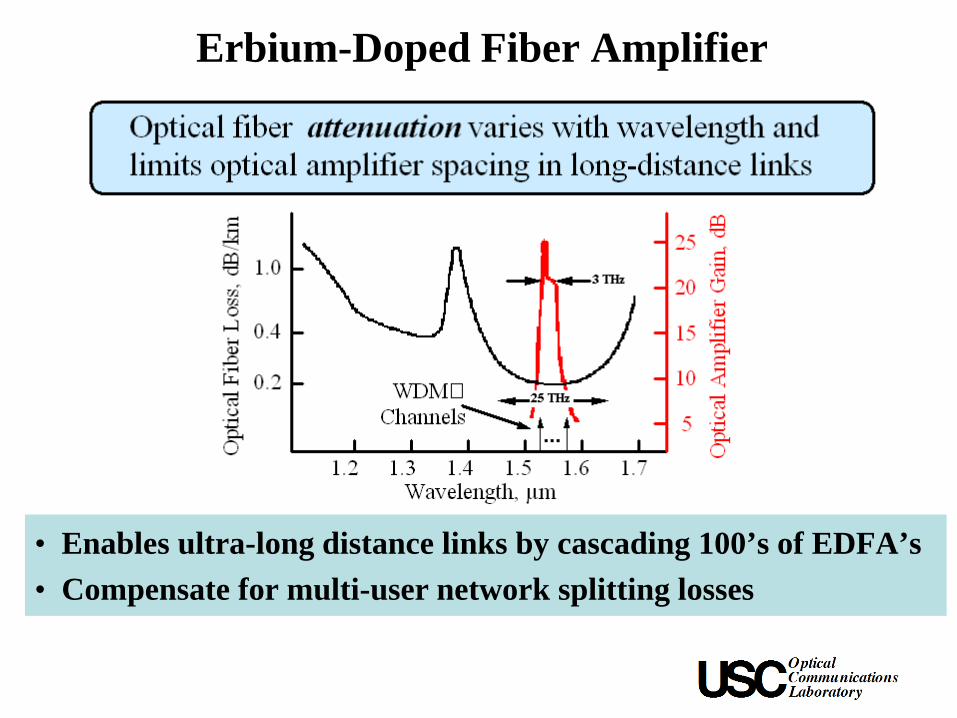
Erbium-Doped Fiber Amplifier
• Enables ultra-long distance links by cascading 100’s of EDFA’s• Compensate for multi-user network splitting losses

Optical Regeneration vs. Amplification
t~~ ~~
t
Regenerator
Regenerating Control
ElectronicsInputDetector Transmitter
Output
tt
Fiber
Optical Amplifier
Input OutputGain
Medium
Pump Source
Output = (Signal Power × Gain) + Added Noise Power
• With optical amplifiers, signal degrading effects accumulate.• The pump source is typically a laser that provides power to the amplifier.

Chromatic DispersionPhoton Velocity (f ) =
Index of Refraction ( f )Speed of Light in a Vacuum
Information Bandwidth of Data
Fourier
fCarrier freq.
vi
vjvk
Temporal Pulse Spreading F [distance, (bit rate)2]
Time
0 1 1 0 1 0
Time
v=velocitytransform
ps/nmkm
•Fabry-Perot diode lasers (low cost) emited light in multiple frequency modes.•CD required use of single-frequency lasers for high-capacity systems.•Bragg gratings were incorporated into the active/passive cavity regions to produce DFB/DBR lasers that were more frequency selective.

• Networks
User Node
1 N
4
32
Optical Network
λ3
λ4
Wavelength-Dependent Routing
WDM Systems• Point-to-Point
Tx’s
Wavelength Multiplexer
λ1λ2
λn
...
... ... Rx’s
Wavelength Demultiplexer
λ1 λ2 … λn
λ λ1λ2
λn
λ -MUXλ
DEMUXλ -
DEMUX
Capacity Increase
• Each λ is like a telephone number in the telephone network.

Wideband Amplifiers Enable WDM(a) Regeneration
(b) Wideband Optical Amplification
Reg λ1
Reg λ2
Reg λ3
Reg λ4
DMUX
MUX
λ1 . . . λ4 λ1 . . . λ4
λ1 . . . λ4 λ1 . . . λ4OA
Reg = detectorelectronicslaser
Fiber

50
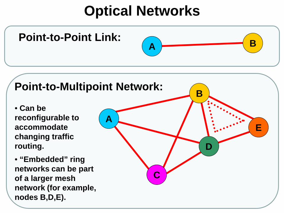
Optical Networks
Point-to-Point Link:
Point-to-Multipoint Network:
• Can be reconfigurable to accommodate changing traffic routing.• “Embedded” ring networks can be part of a larger mesh network (for example, nodes B,D,E).
A
B
A B
C
D
E
51
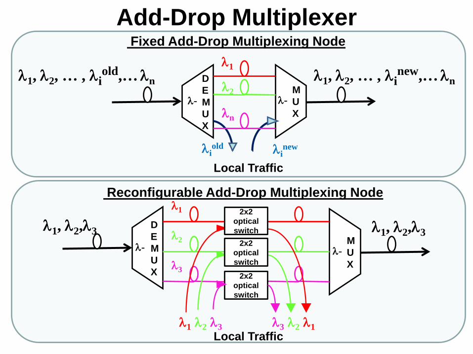
λ1, λ2, … , λiold,… λn λ2
λn
λiold λi
new
λ-
2x2 opticalswitch
λ1, λ2,λ3λ1, λ2,λ3
λ1
λ2
λ3
λ1 λ2 λ3 λ1λ2λ3
Fixed Add-Drop Multiplexing Node
Reconfigurable Add-Drop Multiplexing Node
Add-Drop Multiplexerλ1
DEMUX
λ-MUX
λ-MUX
λ-
DEMUX
2x2 opticalswitch
2x2 opticalswitch
λ1, λ2, … , λinew,… λn
Local Traffic
Local Traffic
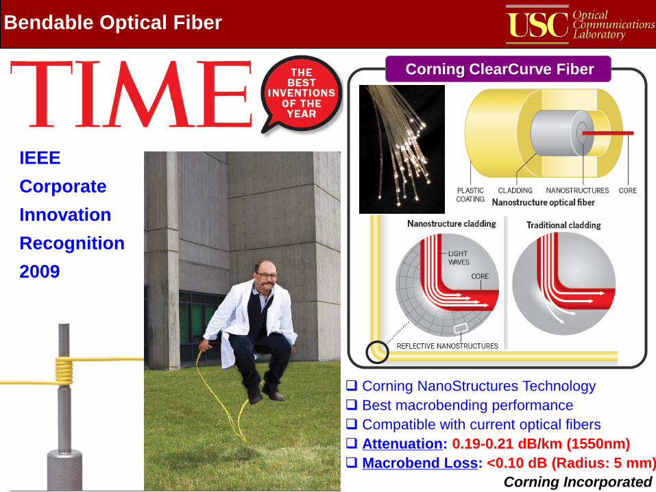
Bendable Optical Fiber
Corning Incorporated
Corning ClearCurve Fiber
Corning NanoStructures Technology Best macrobending performance Compatible with current optical fibers Attenuation: 0.19-0.21 dB/km (1550nm) Macrobend Loss: <0.10 dB (Radius: 5 mm)
IEEE Corporate Innovation Recognition 2009
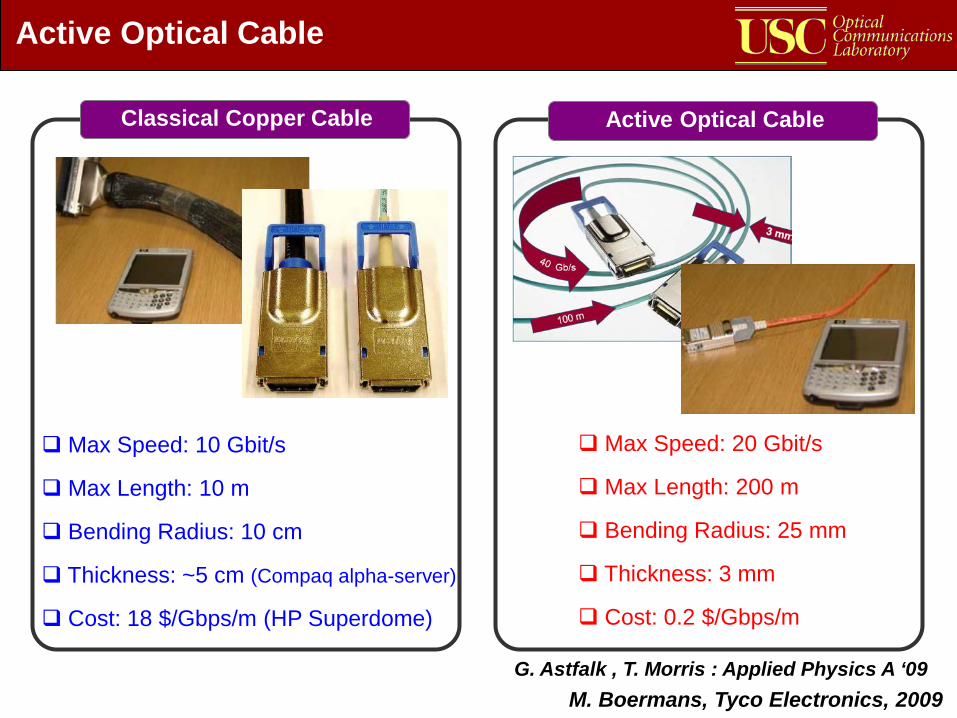
Active Optical Cable
Max Speed: 10 Gbit/s
Max Length: 10 m
Bending Radius: 10 cm
Thickness: ~5 cm (Compaq alpha-server)
Cost: 18 $/Gbps/m (HP Superdome)
M. Boermans, Tyco Electronics, 2009
Max Speed: 20 Gbit/s
Max Length: 200 m
Bending Radius: 25 mm
Thickness: 3 mm
Cost: 0.2 $/Gbps/m
Classical Copper Cable Active Optical Cable
G. Astfalk , T. Morris : Applied Physics A ‘09

“You can transmit∞ bandwidth
over0 distance !!”
L. Mollenauer, 1990
54
Source: Tingye Li and Herwig Kogelnik
Bit-Rate Distance ProductBi
t Rat
e -D
ista
nce
( Gb/
s
km)
1975 1980 1985 1990 1995 2000 2005 2010Year
1101
102
103
104
105
106
107
108 WHAT’S NEXT ??
Spectrally-Efficient Modulation Formats WDM + Optical Amplifiers Optical Amplifiers Coherent Detection 1.5µm Single-Frequency Laser 1.3µm SM Fiber 0.8µm MM Fiber
109
55