Embed Size (px)
Citation preview

Digital Logic System Dr. Bushra A. Sultan
1
Undergraduate Studies
University of Baghdad
Dr. Bushra A. Sultan College of science
Department of Computer
Science
Subject : Digital Logic System
Class : 1'st
Semester: First
Lecture 1
1. Digital Computers:
The characteristic of the digital systems is its manipulation of discrete
elements of information. Example discrete elements may be electrical impulses,
the decimal digits, the letters of alphabet, arithmetic operations, punctuation
marks and any other meaningful symbols. Discrete elements of information are
represented in a digital system by physical quantities called signals. Electrical
signals such as voltages are the most common. The signals in all present-day
electronic digital system s have only two discrete values and are said to be binary.
2. Number Systems ( Binary, Octal , Decimal and Hexadecimal):
Example: (7329.54)10=103*7+10
2*3+10
1*2+10
0*9+10
-1 *5+10
-2*4
=7000+300+20+9+0.5+0.04
When the base is equal to 10 the numbering system is named Decimal and
the coefficients range is (0,1,2,3,4,5,6,7,8,9)
In general a number with decimal points is represented by a series of coefficients as
follows:
(an….a3 a2 a1 a0 . a-1 a-2 a-3……a-m)10
The aj coefficients are one of the digits (0, 1, 2, 3…,9)
a3*103
+ a2*102
+ a1*101
+ a0*100
+ a-1*10-1
+ a-2*10-2
+ a-3*10-3
The Binary number system is a different number system, the coefficients are
(0 and 1) only and the base or radix 2, Ex:

Digital Logic System Dr. Bushra A. Sultan
2
When the base is equal to 8 the numbering system is named Octal and the
coefficients range is (0, 1 , 2, 3, 4, 5, 6, 7), Ex:
When the base is equal to 16 the numbering system is named Hexadecimal
and the coefficients range is (0, 1, 2, 3, 4, 5, 6, 7, 8, 9, A, B, C, D, E, F),
where A=10, B=11, C=12, D=13, E=14, F=15. Ex :
In general a number expressed in base (r) system has coefficients (0, 1….r-1),
multiplied by power of r
rn
*an+…….+ r3
*a3+r2
*a2+r1
*a1+r0
*a0+r-1
*a-1+r-2
*a-2+........r-m
*a-m
When the base of the number is less than (10) the needed (r ) digit of the
coefficients are borrowed from the decimal system. If the base is greater than (10)
then the letters of the alphabet are used.

Digital Logic System Dr. Bushra A. Sultan
3
Lecture 2
3. Conversion from Decimal to Other Bases and vice versa.
3. A The conversion from any base r to decimal:
A number expressed in base r can be converted to its decimal equivalent
by multiplying each coefficient with corresponding power of r and adding.
Ex:
72 7
1 7
0 7
-1
( 6 3 0 . 4 )7 =6*72+3*7
1+0*7
0+4*7
-1
= 49*6+21+0+4/7= 294+21+0+0.571=(315.571)10
82 8
1 8
0 8
-1
( 6 3 0 . 4 )8 =6*82+3*8
1+0*8
0+4*8
-1
= 64*6+24+0+4/8= 384+24+0+0.5=(408.5)10
23 2
2 2
1 2
0 2
-1 2
-2 2
-3
( 1 1 1 0 . 1 0 1 )2 =1*23+1*2
2+1*2
1+0*2
0+1*2
-1+0*2
-2+1*2
-3
=8+4+2+0+1/2+0+1/8=14+0.5+0+0.125
=(14.625)10
162 16
1 16
0 16
-1
( F 3 A . B )16 =F*162+3*16
1+A*16
0+B*16
-1
= 15*162+3*16
1+10*16
0+11*16
-1
=15*256+3*16+10*1+11/16
=3840+48+10+0.6875=(3898.6875)10
3. B The Conversion from decimal to any base r:
Note: The conversion is more convenient if the number is separated into
an integer part and a fraction part so the conversion of each part is done
separately.
Ex: Convert the decimal number (14.625) to binary (base 2)
Integer Remainder
14÷2
7÷2 0 a0
3÷2 1 a1
1÷2 1 a2
0 1 a3
(14)10=(1110)2

Digital Logic System Dr. Bushra A. Sultan
4
Integer Fraction
0.625
* 2 =1. 25
a-1 1 0.25
*2 =0. 5
a-2 0 0.5
*2 =1. 0
a-3 1 0.00
(0.625)10=(0.101)2
(14. 625)10=(1110.101)2
Ex: Convert the decimal number (315.571) to (base 7)
Integer Remainder
315÷7
45÷7 0 a0
6÷7 3 a1
0 6 a2
(315)10=(630)7
Integer Fraction
0. 571
* 7 =3. 997
a-1 3 0.997
*7 =6. 979
a-2 6 0.979
*7 =6.853
a-3 6 0.853
(0. 571)10=(0.366)7
(315.571)10=(630. 366)7
Ex: Convert the decimal number (314.21) to Hexadecimal (base 16)
Integer Remainder
314÷16
19÷16 A a0
1÷16 3 a1
0 1 a2
(314)10=(13A)16

Digital Logic System Dr. Bushra A. Sultan
5
Integer Fraction
0. 21
* 16 =3. 36
a-1 3 0.36
*16 =5. 76
a-2 5 0.76
*16 =12.16
a-3 C 0.16
(0. 21)10=(0.35C)16
(314.21)10=(13A .35C)16
HW. Convert the following number to the indicated bases
1. (214.3)10 to base 4. 2. (10101.101)2 to decimal. 3. (124.03)5 to base 7. Hint. (124.03)5 =(?)10 =(?)7 4. (346.67)10 to base 16. 5. (124.34)10 to base 12. 6. (110101.1101)2 to decimal. 7. (42F.CB)16 to decimal 8. (111011010.001101)2 to Octal.
Hint. (111011010.001101)2 =(?)10 =(?)8 9. (12A.8)12 to Decimal
Digital Logic System Dr. Bushra A. Sultan
6
Lecture 3
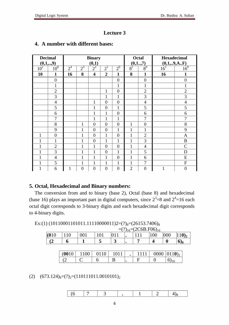
4. A number with different bases:
5. Octal, Hexadecimal and Binary numbers:
The conversion from and to binary (base 2), Octal (base 8) and hexadecimal
(base 16) plays an important part in digital computers, since 23=8 and 2
4=16 each
octal digit corresponds to 3-binary digits and each hexadecimal digit corresponds
to 4-binary digits.
Ex:(1) (10110001101011.11110000011)2=(?)8=(26153.7406)8
=(?)16=(2C6B.F06)16
(010 110 001 101 011 . 111 100 000 110)2
(2 6 1 5 3 . 7 4 0 6)8
(0010 1100 0110 1011 . 1111 0000 0110)2
(2 C 6 B . F 0 6)16
(2) (673.124)8=(?)2=(110111011.0010101)2
(6 7 3 . 1 2 4)8
Decimal
(0,1,..,9)
Binary
(0,1)
Octal
(0,1..,7)
Hexadecimal
(0,1,..9,A..F)
101 10
0 2
4 2
3 2
2 2
1 2
0 8
1 8
0 16
1 16
0
10 1 16 8 4 2 1 8 1 16 1
0 0 0 0
1 1 1 1
2 1 0 2 2
3 1 1 3 3
4 1 0 0 4 4
5 1 0 1 5 5
6 1 1 0 6 6
7 1 1 1 7 7
8 1 0 0 0 1 0 8
9 1 0 0 1 1 1 9
1 0 1 0 1 0 1 2 A
1 1 1 0 1 1 1 3 B
1 2 1 1 0 0 1 4 C
1 3 1 1 0 1 1 5 D
1 4 1 1 1 0 1 6 E
1 5 1 1 1 1 1 7 F
1 6 1 0 0 0 0 2 0 1 0
Digital Logic System Dr. Bushra A. Sultan
7
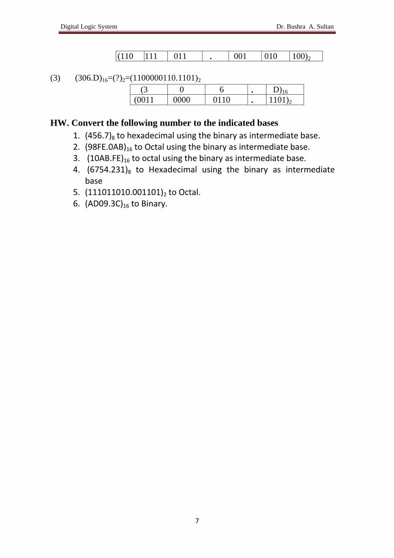
(110 111 011 . 001 010 100)2
(3) (306.D)16=(?)2=(1100000110.1101)2
(3 0 6 . D)16
(0011 0000 0110 . 1101)2
HW. Convert the following number to the indicated bases
1. (456.7)8 to hexadecimal using the binary as intermediate base. 2. (98FE.0AB)16 to Octal using the binary as intermediate base. 3. (10AB.FE)16 to octal using the binary as intermediate base. 4. (6754.231)8 to Hexadecimal using the binary as intermediate
base 5. (111011010.001101)2 to Octal. 6. (AD09.3C)16 to Binary.

Digital Logic System Dr. Bushra A. Sultan
8
Lecture 4
6. Arithmetic Operation:
Addition (+), Subtraction (-), Multiplication (*)
Carry (1) (1) (1) (1)
Augend (1 0 1 1 0 1)2
Addend (1 0 0 1 1 1)2 +
Sum (10 1 0 1 0 0)2
10
Borrow 0 0 10
Minuend (1 0 1 1 0 1)2
Subtrahend (1 0 0 1 1 1)2 -
Difference (0 0 0 1 1 0)2
Multiplicand ( 1 0 1 1)2
Multiplier ( 1 0 1)2 *
(1) 1 0 1 1
0 0 0 0 +
1 0 1 1
Product (1 1 0 1 1 1)2
HW. Perform the following operation without converting to decimal
or any other base:
1. (1101.01 * 10.1)2= 2. (D39 + 16A)16= 3. (243.13 - 144.02)5 = 4. (11100.01 - 1110.11)2= 5. (243 * 24)5=
6. (FB09 - ED32)16= 7. (227.65 + 624.31)8= 8. (FD0D - AE21)16 =
9. (323 * 32)4 =

Digital Logic System Dr. Bushra A. Sultan
9
7. Complement and Subtraction using 1’s and 2’s Complement.
7.1 Complement:
Complements are used in digital computers for simplifying the subtraction
operation and for logical manipulation. There are two types of complements for
each base (r ) system:
I. The r’s complements
II. The (r-1)’s complements
7.1.1 The r’s complements: A positive number N in base r with an integer part of
n digits, the r’s complement of N is defining as follows:
Ex:
a) The 2’s complement of (101100)2 is N=101100, r=2, n=6 →the 2’s
complement equal to : (26)10-(101100)2=(1000000-101100)2= (10100)2
b) The 2’s complement of (0.0110)2 is N=0.0110, r=2, n=0 →the 2’s
complement equal to : (20)10-(0.0110)2=(1-0.0110)2=(0.1010)2
7.1.2 The (r-1)’s complements:
A positive number N in base r with an integer part of n digits and a fraction
part of m digits, the (r-1)’s complement of N is define as follows:
a) The 1’s complement of (101100)2 is N=101100, r=2, n=6 ,m=0→the 1’s
complement equal to: (26-2
0)10-(101100)2=(1000000-1)2-(101100)2
1 1 1
0 10 10 10 10
(1 0 0 0 0 0 0)2 -
( 1 0 1 1 0 0)2
(0 0 1 0 1 0 0)2
1 1
0 . 10 10 10
(1 . 0 0 0 0)2 -
( 0 1 1 0)2
(0 . 1 0 1 0)2
rn-N for N≠0
0 for N=0
rn-r
-m-N

Digital Logic System Dr. Bushra A. Sultan
10
=(111111-101100)2=(10011)2
b) The 1’s complement of (0.0110)2 is N=0.0110, r=2, n=0 ,m=4→the 1’s
complement equal to: (20-2
-4)10-(0.0110)2=(1-0.0001)2-(0.0110)2
=(0.1111-0.0110)2=(0.1001)2
1 1 1 1 1 1
0 10 10 10 10 10 10
(1 0 0 0 0 0 0)2 -
( 1)2
(0 1 1 1 1 1 1)2
(1 1 1 1 1 1)2 -
(1 0 1 1 0 0)2
(0 1 0 0 1 1)2
1 1 1
0 . 10 10 10 10
(1 . 0 0 0 0)2 -
( 1)2
(0 . 1 1 1 1)2
(0 . 1 1 1 1)2 -
(0 . 0 1 1 0)2
(0 . 1 0 0 1)2

Digital Logic System Dr. Bushra A. Sultan
11
Lecture 5
7.2 Subtraction using Complement:
The direct method of subtraction taught in elementary schools uses the
borrow concept. This method seems to be easiest when people perform
subtraction with paper and pencil, but this method is found to be less efficient
when it is implemented by means of digital computers.
7.2.1 Subtraction using r’s Complement:
The subtraction of two positive numbers (M-N), both of base r, may be done as
follows
1. M+(r’s complement of N)=
2. Inspect the result for an end carry.
a. If carry occurs discard it.
b. If no carry the result is equal to –(r’s complement of the result of step 1).
Ex. (110101-100010)2 subtract using 2’s complement.
(110101-100010)2= 110101+[ 2’s complement of 100010]
=110101+[ 26-100010]
=110101+[1000000-100010]2
=(110101+011110)2=1 010011→Result=(10011)2 (rule 2.a)
H.W (100010-110101)2 subtract using 2’s complement.
7.2.2 Subtraction using (r-1)’s Complement:
The subtraction of two positive numbers (M-N), both of base r, may be done as
follows:
1. M+[(r-1)’s complement of N]=
2. Inspect the result for an end carry.
a. If carry occurs, add (1) to the least significant digit (LSD).
b. If no carry the result is equal to –[(r-1)’s complement of the result of step
1).
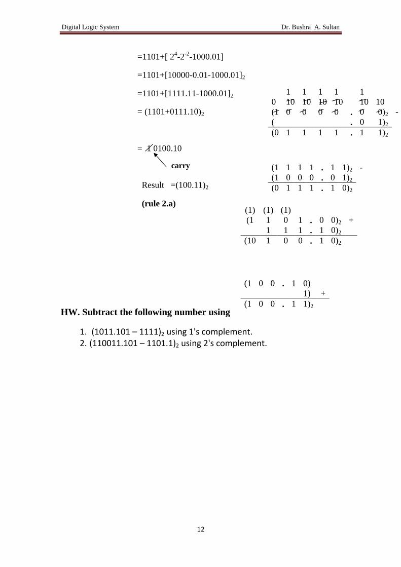
Ex. (1101-1000.01)2 subtract using 1’s complement.
(1101-1000.01)2= 1101+[ 1’s complement of 1000.01]
carry
Digital Logic System Dr. Bushra A. Sultan
12
=1101+[ 24-2
-2-1000.01]
=1101+[10000-0.01-1000.01]2
=1101+[1111.11-1000.01]2
= (1101+0111.10)2
= 1 0100.10
Result =(100.11)2
(rule 2.a)
HW. Subtract the following number using
1. (1011.101 – 1111)2 using 1's complement. 2. (110011.101 – 1101.1)2 using 2's complement.
1 1 1 1 1
0 10 10 10 10 10 10
(1 0 0 0 0 . 0 0)2 -
( . 0 1)2
(0 1 1 1 1 . 1 1)2
(1 1 1 1 . 1 1)2 -
(1 0 0 0 . 0 1)2
(0 1 1 1 . 1 0)2
(1) (1) (1)
(1 1 0 1 . 0 0)2 +
1 1 1 . 1 0)2
(10 1 0 0 . 1 0)2
(1 0 0 . 1 0)
1) +
(1 0 0 . 1 1)2
carry

Digital Logic System Dr. Bushra A. Sultan
13
Lecture 6
8. Alphanumeric Codes:
Many applications of digital computers require handling name as well as
letters. An alphanumeric code is a binary code of a group of elements
consisting of 10 decimal digits, the 26 letter of alphabet, certain number of
special symbols such as $,;,’,…etc. The total number of elements in an
alphanumeric group is >36. So it must be coded with minimum number of bits
(26=64)
ASCII code (American Standard Code for Information Interchange) 7-bit
Length code.
EBCDIC code (Extended BCD Interchange Code) 8-bit Length code.
Letters ASCII code Letters ASCII code
decimal binary decimal binary
A 65 100 0001 a 97 110 0001
B 66 100 0010 b 98 110 0010
:
Z 90 101 1010 z 122 111 1010
0 48 011 0000
1 49 011 0001
:
9 57 011 1001
$ 36 010 0100
( 40 010 1000
? 47 010 1111

Digital Logic System Dr. Bushra A. Sultan
14
9. Binary Logic and Gates
9.1 Binary logic:
Binary logic deals with the variables take two discrete values true and
false, yes and no. Binary logic is used to describe, in a mathematical way,
the manipulation and processing of binary information. It particularly suited
for analysis and design of digital systems. Binary Logic is equivalent to
Boolean algebra.
9.2 Definition of Binary logic:
Binary logic consists of binary variables and logic operation. The
variables are designated by letters e.g. A, B, C, r, w, x, y with only two
distinct values: 1 and 0. The basic logical operators are AND, OR and NOT.
AND similar to * in binary arithmetic
OR similar to + in binary arithmetic but 1+1=10 (in binary arithmetic)
1+1= 1 (in binary logic)
x 1
0 0 0 1 1
y 1
0 0 1 0 1
x.y 1
0 0 0 0 1
x+y 1
0 0 1 1 1
x’ 1
0 1 1 0 0
Timing diagram illustrate the
response of each circuit to each of 4
input binary combinations
(00,01,10,11)

Digital Logic System Dr. Bushra A. Sultan
15
9.3 Logic Gates:
Digital Circuits, Switching Circuits, Logic Circuits and Logic Gates are
the same. Gates are block of hardware that produces a logic-1 or logic-0 output
signal if input logic requirement are satisfied.
AND
Inputs Output
x y x.y
0 0 0
0 1 0
1 0 0
1 1 1
OR
Inputs Output
x y x+y
0 0 0
0 1 1
1 0 1
1 1 1
NOT
Input Output
x x̅
0 1
1 0
The mathematical system of binary logic is better known as Boolean or
switching algebra. This algebra is conveniently used to describe the operation
of complex network of digital circuits. Designers of digital systems use
Boolean algebra to transform circuits diagram to algebraic expression and vice
versa.
10. Integrated Circuits:
Is a small silicon semiconductor crystal, called a chip, containing electrical
components such as transistor, diodes, resistor and capacitor. The various
components are interconnected inside the chip to form electronic circuits. The
chip is mounted on a metal or plastic packaged, and connection are welded to
external pins to form the IC. IC’s come in two types: 1) Flat package
2) dual package

Digital Logic System Dr. Bushra A. Sultan
16
As the technology of ICs has improved, number of gates that can be put on
a single silicon chip has increased considerably.
SSI chip contains less than 10 gates.
MSI chip contains between 10 to 100 gates.
LSI chip contains between 100 to 1000 gates.
VLSI chip contains between thousands of gates.
11. Basic Identity of Boolean Algebra:
a b
1 X+0=X X.1=X Identity Element
2 X+1=1 X.0=0
3 X+X=X X.X=X
4 ∀ 𝑋 ∈𝐵 ∃ �̅� 𝑠. 𝑡
X+X̅=1 X.X̅=0 Complement
Definition
5 X̅̅=X
6 X+Y=Y+X X.Y=Y.X Commutative Law
7 X+(Y+Z)=(X+Y)+Z X.(YZ)=(XY).Z Associative Law
8 X.(Y+Z)=(X.Y)+(X.Z) X+(Y.Z)=(X+Y).(X+Z) Distributive Law
9 (X + Y)̅̅ ̅̅ ̅̅ ̅̅ ̅̅ = X̅. Y̅ (X. Y)̅̅ ̅̅ ̅̅ ̅ = X̅ + Y̅ Demorgan's
Theorem
10 X+XY=X X(X+Y)=X Absorption
Theorem

Digital Logic System Dr. Bushra A. Sultan
17
Lecture 7
12. Boolean Functions:
Boolean functions are formed from binary variables, logic operators and
equal sign. The function value can be either 1 or 0:
Ex: F1 = 𝑥𝑦𝑧̅
F2 = 𝑥 + �̅�𝑧
A Boolean function also represented in truth table. A Boolean function
may be transformed from an algebraic expression into a logic diagram or
circuit composed of AND, OR and NOT get.
NOTE: The operator precedence for evaluating Boolean expression is:
1. Parentheses 2. NOT 3. AND 4. OR
Boolean
Expression Logic Circuit Truth Table (T.T.)
F1 = 𝑥𝑦𝑧̅
Truth Table of F1
x y z z' F1=xyz'
0 0 0 1 0
0 0 1 0 0
0 1 0 1 0
0 1 1 0 0
1 0 0 1 0
1 0 1 0 0
1 1 0 1 1
1 1 1 0 0
F2 = 𝑥 + �̅�𝑧
Truth Table of F2
x y z y' y'z x+y'z
0 0 0 1 0 0
0 0 1 1 1 1
0 1 0 0 0 0
0 1 1 0 0 0
1 0 0 1 0 1
1 0 1 1 1 1
1 1 0 0 0 1
Boolean Expression
Logic Circuit or Diagram Truth Table
expression

Digital Logic System Dr. Bushra A. Sultan
18
1 1 1 0 0 1
Complement of a function:
The complement of any function F is F`or F̅ its value can be obtained by
interchange the (1's to 0's) and (0's to 1's) in the value of F. the complement of
a function may be obtained algebraically through Demerger's theory.
Ex: Fined F̅ of F1, F2 and F3.
𝐹1̅̅̅̅ = (𝑥𝑦𝑧̅)̅̅ ̅̅ ̅̅ ̅̅ = �̅� + �̅� + 𝑧̅̅ = �̅� + �̅� + 𝑧
𝐹2̅̅̅̅ = (𝑥 + �̅�𝑧)̅̅ ̅̅ ̅̅ ̅̅ ̅̅ ̅ = �̅�. �̅�𝑧̅̅ ̅ = �̅�. (�̅̅� + 𝑧̅) = �̅�. (𝑦 + 𝑧̅)
𝐹3̅̅̅̅ = �̅�𝐵 + 𝐶�̅�̅̅ ̅̅ ̅̅ ̅̅ ̅̅ ̅̅ = �̅�𝐵̅̅ ̅̅ . 𝐶�̅�̅̅ ̅̅ = (�̅̅� + �̅�). (𝐶̅ + �̅̅�) = (𝐴 + �̅�). (𝐶̅ + 𝐷)
13. Simplification of Boolean Functions using Boolean algebra.
Literal: is a single variable within the term that may be complemented or
not. When a Boolean function is implemented with logic gates, each literal in
Boolean function is designated an input to gate and each terms is implemented
with gate. The minimization of a number of literal and the number of terms
results in circuit with less equipment. Boolean algebra is a useful tool for
simplifying digital circuit. Functions below simplified by using Boolean
algebra.
Reduce the following Boolean expression using Boolean algebra to the
indicated number of literals:
1) F1=x'yz+x'yz'+xy to one literal
= x'yz+x'yz'+xy
=x'y(z+z') +xy (Distributive law)
=x'y.1+xy (Complement definition)
=x'y+xy (Identity element)
=y(x'+x) (Distributive law)
=y.1 (Complement definition)
F1=y (Identity element)
2) F2=x+(x'y) to two literals
=(x+x')(x+y) (Distributive law)
=1.(x+y) (Complement definition)
F2=x+y (Identity element).
3) F3=xy+x'z+yz to four literals

Digital Logic System Dr. Bushra A. Sultan
19
= xy+x'z+yz.1 (Iidentity element)
= xy+x'z+yz(x+x') (Complement definition)
= xy+x'z+xyz+x'yz (Distributive law)
=xy(1+z)+x'z(1+y) (Distributive law)
=xy.1+x'z.1 (x+1)=1
F3=xy+x'z (Iidentity element)
Truth Table of F3= xy+x'z
x Y z x' xy x'z F3=xy+x'z
0 0 0 1 0 0 0
0 0 1 1 0 1 1
0 1 0 1 0 0 0
0 1 1 1 0 1 1
1 0 0 0 0 0 0
1 0 1 0 0 0 0
1 1 0 0 1 0 1
1 1 1 0 1 0 1
4) F4 = 𝑥 + 𝑦(𝑧 + 𝑥 + 𝑧̅̅ ̅̅ ̅̅ ̅) to two literals = 𝑥 + 𝑦(𝑧 + �̅�𝑧̅) (Demorgan's theory )
= 𝑥 + 𝑦(𝑧 + �̅�)(𝑧 + 𝑧̅) (Distributive law)
= 𝑥 + 𝑦(𝑧 + �̅�). 1 (Complement definition) = 𝑥 + 𝑦𝑧 + 𝑦�̅� (Identity element) = (𝑥 + 𝑦�̅�) + 𝑦𝑧 (Commutative law) = (𝑥 + 𝑦)(𝑥 + �̅�) + 𝑦𝑧 (Distributive law) = (𝑥 + 𝑦). 1 + 𝑦𝑧 (Complement definition)
= 𝑥 + 𝑦 + 𝑦𝑧 (Identity element) = 𝑥 + 𝑦(1 + 𝑧) (Distributive law) = 𝑥 + 𝑦. 1 (Complement definition)
𝐹4 = 𝑥 + 𝑦 (Identity element)
F5 = (𝐴𝐵 + 𝐶𝐷)(𝐴𝐵 + 𝐶) to four literals is = 𝐴𝐵 + (𝐶𝐷 . 𝐶) (Distributive law)
𝐹5 = 𝐴𝐵 + 𝐶𝐷 (X . X=X)

Digital Logic System Dr. Bushra A. Sultan
20
HW.
Q1 Obtain the logical expression of T1, T2, T3 and F in term of the input variables, for the following logic circuits.
(a)
Q2) Reduce the following Boolean expression using Boolean algebra to the indicated number of literals:
1. A̅B(D + C̅D) + B(A + A̅ CD) to one literal
2. (A + A̅)(AB + ABC̅) to two literals
3. XY + XYZ + XYZ̅ + X̅YZ to three literals
4. (XY+Z)’ (X’Y’Z’) to 3 literals
Q3) Draw the logic diagram of the following Boolean function without simplifying them
1. F1 = BC̅ + AD 2. F2 = B(C̅ + A)
3. F3 = (X + Y)̅̅ ̅̅ ̅̅ ̅̅ ̅(X̅ + Y)

Digital Logic System Dr. Bushra A. Sultan
21
Lecture 8
14. Canonical and Standard forms:
14. A Canonical form: canonical forms (Sum of Minterms or Product of
Maxterms) are used to obtain the function from the given truth table
x y z Minterms Notation Maxterms Notation
0 0 0 x'y'z' m0 (x+y+z) M0
0 0 1 x'y'z m1 (x+y+z') M1
0 1 0 x'yz' m2 (x+y'+z) M2
0 1 1 x'yz m3 (x+y'+z') M3
1 0 0 xy'z' m4 (x'+y+z) M4
1 0 1 xy'z m5 (x'+y+z') M5
1 1 0 xyz' m6 (x'+y'+z) M6
1 1 1 xyz m7 (x'+y'+z') M7
Variable
Primed if =0
Imprimed=1
Variable
Primed if =1
Imprimed=0
14. A .1 Sum of Minterms:
A Boolean function may be expressed algebraically as a sum of minterms from a
given truth table by:
Step1: forming a minterm for each combination of the variables which produce 1
in the function.
Step2: OR all of the minterms in step1.
Example: From the given truth table express F as a sum of minterms
Given Solution
Inputs Output Step1 Step2
x y z F minterms Sum of minterms
0 0 0 0 F= x'y'z+ x'yz+ xyz
0 0 1 1 x'y'z F=m1+m3+m7
0 1 0 0 F(x,y,z)=Σ(1,3,7)
0 1 1 1 x'yz
1 0 0 0
1 0 1 0
1 1 0 0

Digital Logic System Dr. Bushra A. Sultan
22
1 1 1 1 xyz
From the table F' can be expressed as a sum of minterms as follows:
Step1: forming a minterm for each combination of the variables which produce 0
in the function.
Step2: OR all of the minterms in step1.
Example: From the given truth table express F' as a sum of minterms
Given Solution
Inputs Inputs Step1 Step2
x y z F minterms Sum of minterms
0 0 0 0 x'y'z' F'= x'y'z'+ x'yz'+ xy'z'+ xy'z+ xyz'
0 0 1 1 F'=m0+m2+m4+ m5+m6
0 1 0 0 x'yz' F'(x,y,z)=Σ(0,2,4,5,6)
0 1 1 1
1 0 0 0 xy'z'
1 0 1 0 xy'z
1 1 0 0 xyz'
1 1 1 1
14. A .2 Product of Maxterms:
A Boolean function may be expressed algebraically as a product of maxterms
from a given truth table by:
Step1: forming a maxterms for each combination of the variables which
produce 0 in the function.
Step2: form the AND of all the maxterms in step1.
Example: From the given truth table express F as a product of maxterms
Given Solution
Inputs Inputs Step1 Step2
x y z F maxterms Product of maxterms
0 0 0 0 (x+y+z) F=(x+y+z) (x+y'+z) (x'+y+z) (x'+y+z') (x'+y'+z)
0 0 1 1 F= M0.M2.M4. M5.M6
0 1 0 0 (x+y'+z) F(x,y,z)=Π(0,2,4,5,6)
0 1 1 1
1 0 0 0 (x'+y+z)
1 0 1 0 (x'+y+z')
1 1 0 0 (x'+y'+z)
1 1 1 1

Digital Logic System Dr. Bushra A. Sultan
23
From the table F' can be expressed as follows:
Step1: forming a maxterm for each combination of the variables which produce 1
in the function.
Step2: form the AND of all the maxterms in step1.
Example: From the given truth table express F' as a product of maxterms
Given Solution
Inputs Inputs Step1 Step2
x y z F maxterms Product of maxterms
0 0 0 0 F'= (x+y+z') (x+y'+z') (x'+y'+z')
0 0 1 1 (x+y+z') F'=M1.M3.M7
0 1 0 0 F'(x,y,z)= Π (1,3,7)
0 1 1 1 (x+y'+z')
1 0 0 0
1 0 1 0
1 1 0 0
1 1 1 1 (x'+y'+z')
14. B. Standard Forms:
Sum terms: single variable or logical sum of several variables such as (A, B, (x+y),
(A+C')).
Product terms: single variable or logical product of several variables such as (x, y,
AB', CD')
Note: the expression x+y'z (not sum term nor product terms)
14. B.1. Sum of Products (SOP): is a Boolean expression containing AND terms,
called product terms, of one or more literals each. The sum denotes the ORing of
these terms. An example of a function expressed as a sum of product is
F1=y'+xy+x'yz'
The expression contains three product terms (y' one literal, xy two literals and x'yz'
three literals). Their sum is in effect an OR operation. The logic diagram if a sum-of-
product expression consist of a group of AND gates followed by a single OR gate.
14. B.2 Product of Sums (POS): is a Boolean expression containing OR terms,
called sum terms, of one or more literals each. The product denotes the ANDing of
these terms. An example of a function expressed as a product of sum is
F2=x(y'+z)(x'+y+z)
Digital Logic System Dr. Bushra A. Sultan
24
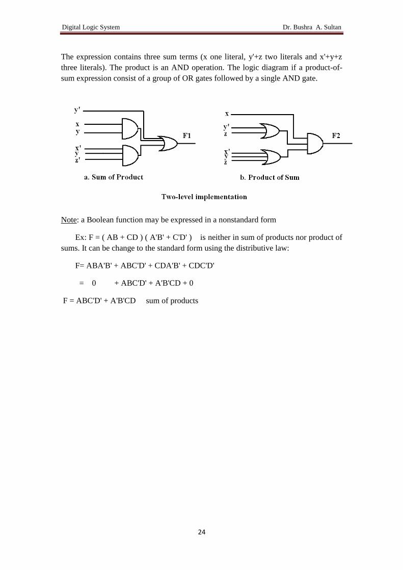
The expression contains three sum terms (x one literal, y'+z two literals and x'+y+z
three literals). The product is an AND operation. The logic diagram if a product-of-
sum expression consist of a group of OR gates followed by a single AND gate.
Note: a Boolean function may be expressed in a nonstandard form
Ex: F = ( AB + CD ) ( A'B' + C'D' ) is neither in sum of products nor product of
sums. It can be change to the standard form using the distributive law:
F= ABA'B' + ABC'D' + CDA'B' + CDC'D'
= 0 + ABC'D' + A'B'CD + 0
F = ABC'D' + A'B'CD sum of products

Digital Logic System Dr. Bushra A. Sultan
25
Lecture 9
Example: From the given truth table express F as a sum of minterms then simplify as
a sum of product
Given
x y z F
0 0 0 0
0 0 1 0
0 1 0 1
0 1 1 1
1 0 0 0
1 0 1 0
1 1 0 1
1 1 1 0
Solution: the function equal to 1 in {(2,x'yz'),(3,x'yz),(6,xyz')}
So F=x'yz'+x'yz+xyz' (Sum of Minterms)
Simplification of F
F=x'yz'+x'yz+xyz'
=x'y(z'+z)+xyz' (distributive law)
=x'y.1+xyz' (complement definition)
=x'y+xyz' (identity element)
=y(x'+xz') (distributive law)
=y(x'+x)(x'+z') (distributive law)
=y.1.(x'+z') (complement definition)
=y(x'+z') (identity element)
=x'y+yz' (distributive law)

Digital Logic System Dr. Bushra A. Sultan
26
Example: From the given truth table express F as a product of maxterms then simplify
as a product of sum
Given
x y z F
0 0 0 0
0 0 1 0
0 1 0 1
0 1 1 1
1 0 0 0
1 0 1 0
1 1 0 1
1 1 1 0
Solution: the function equal to 0 in {(0,x+y+z),(1,x+y+z'),(4,x'+y+z), (5,x'+y+z')
,(7,x'+y'+z')}
So F=( x+y+z)( x+y+z')( x'+y+z) (x'+y+z')( x'+y'+z') product of maxterms
Simplification of F
F=( x+y+z) ( x+y+z') (x'+y+z) (x'+y+z') ( x'+y'+z')
=[(x+y)+zz'] [(x'+y)+zz')] ( x'+y'+z') (distributive law)
=[(x+y)+0] [(x'+y)+0] (x'+y'+z') (complement definition)
=(x+y) (x'+y) (x'+y'+z') (identity element)
=(y+xx') ( x'+y'+z') (distributive law)
= (y+0) ( x'+y'+z') (complement definition)
= y(x'+y'+z') (identity element)
= x'y+yy'+yz' (distributive law)

Digital Logic System Dr. Bushra A. Sultan
27
=x'y+0+yz' (complement definition)
=x'y+yz' (identity element)
=y(x'+z') (distributive law) to convert the function from SOP to POS
14.C convert functions to the canonical forms:
14.C.1 conversion to sum of minterms:
It is sometimes convenient to express function in its sum of minterms form by:
a. Expanding the expression in to sum of AND terms (SOP)
b. Each AND term is inspected to see if it contains all the variables. If it missing
one or more variables, it is ANDed with an expression (x+x'), where x is one
of the missing variable
Example: Express the Boolean function F=A+B'C in a sum of minterms.
Solution: the function F has three variables A,B and C. it is in SOP standard form
the first product term (A) missing two variable (B,C); therefore
A= A (B+B') = AB + AB'
This terms still missing one variable (C):
A= AB(C+C') + AB'(C+C')
= ABC + ABC' + AB'C + AB'C'
The second term (B'C) missing one variable (A):
B'C= B'C (A+A') = B'CA + B'CA' rearrange the variable alphabetically
B'C= AB'C + A'B'C
Combining all terms, we have:
F= A + B'C
= ABC + ABC' + AB'C + AB'C' + AB'C + A'B'C

Digital Logic System Dr. Bushra A. Sultan
28
Since (x+x=x) we can eliminate one of the underlined term
F= A'B'C + AB'C' + AB'C + ABC' + ABC
=m1 + m4 + m5 + m6 + m7
F(A,B,C)=Σ(1,4,5,6,7)
14.C.2 conversion to product of maxterms:
To express function in its product of maxterms form by:
a. Expanding the expression in to product of OR terms (POS), using distributive
law
b. Each OR term is inspected to see if it contains all the variables. If it missing
one or more variables, it is ORed with an expression (xx'), where x is one of
the missing variable
Example: Express the Boolean function F= xy +x'z in a product of maxtermes.
First: convert the function into OR terms (POS) by using distributive law:
F= xy +x'z = let a=xy
F= a + x'z = ( a + x' ) ( a + z ) = ( xy + x' ) ( xy + z )
= ( x' + x ) ( x' + y ) ( z + x ) ( z + y )
F = (x' + y ) ( z + x ) ( z + y )POS
The function has three variables x, y and z. each OR term is missing one variable;
therefore:
( x' + y ) = ( x' + y ) + zz' = ( x' + y + z ) ( x' + y + z' )
( z + x ) = ( z + x ) + yy' = ( z + x + y ) ( z + x + y') = ( x + y + z ) ( x + y' + z )
( z + y ) = ( z + y ) + xx' = ( z + y + x ) ( z + y + x' ) = ( x + y + z ) ( x' + y + z )
Combining all terms and removing all those that appear more than once, we
finally obtain:
F= ( x + y + z ) ( x + y' + z ) ( x' + y + z ) ( x' + y + z' )
= M0 M2 M4 M5
F(x,y,z) = Π (0, 2, 4, 5)
14.C.3 Conversions between Canonical forms:

Digital Logic System Dr. Bushra A. Sultan
29
To convert from one canonical form to another: interchanging the symbols Π
and Σ then list those numbers missing in the original form. In order to find the missing
terms, one must realize the total number of minterms and maxterms is 2n, where n is
the number of binary variables in the function.
Example: convert the Boolean function F(x,y,z)= Σ(0,2,4,5) to the other canonical
form.
The number of variables is three (x, y, z), therefore the total numbers is in the range
(0..23-1)=(0..7) therefore, F(x,y,z)= Π (1,3,6,7)
Lecture 10
15. Other Logical Operations:
Name Graphical symbol Algebraic
function
Truth
table
AND
F=x.y x y F
0 0 0
0 1 0
1 0 0
1 1 1
OR
F=x+y x y F
0 0 0
0 1 1
1 0 1
1 1 1
NOT, Inverter
x x'
0 1
1 0
Buffer
x x
0 0
1 1
NAND
F= (xy)'
= x↑y
x y F
0 0 1
0 1 1
1 0 1
1 1 0

Digital Logic System Dr. Bushra A. Sultan
30
NOR
F=(x+y)'
= x↓y
x y F
0 0 1
0 1 0
1 0 0
1 1 0
XOR
F=x'y+xy'
=x⊕y
x y F
0 0 0
0 1 1
1 0 1
1 1 0
XNOR
F=x'y'+xy
=(x⊕y)'
= x⨀y
x y F
0 0 1
0 1 0
1 0 0
1 1 1
Exclusive OR (XOR): odd function equal to 1 if the numbers of the input
variables have an odd number of 1's and 0 otherwise. The construction of 2-input
Exclusive-OR function is shown below. It is normally implemented by cascading
2-input gates, as shown in below:
The following identities apply to Exclusive –OR operation:
x ⊕0=x , x⊕x=0 , x ⊕y' = x' ⊕y = (x ⊕y)'
x ⊕1=x' , x ⊕x'=1 ,
Equivalence or Exclusive NOR: even function equal to 1 if the number of 0's in
the input variables are even and 0 otherwise.
XOR and Equivalence are both commutative and associative.
x↑y=(xy)'=x'+y' y↑x=(yx)'=y'+x'=x'+y' ∴ NAND is
commutative
x y z F=x⊕y⊕ 𝑧
0 0 0 0
0 0 1 1
0 1 0 1
0 1 1 0
1 0 0 1
1 0 1 0
1 1 0 0
1 1 1 1

Digital Logic System Dr. Bushra A. Sultan
31
x↓y=(x+y)'=x'y' y↓x=(y+x)'=y'x'=x'y' ∴ NOR is commutative
(x↑y)↑z=(xy)'↑z=((xy)' z)'= (xy)"+ z'= xy+z'
x↑(y↑z)= x↑(yz)'=(x' (yz)')'= x'+(yz)"=x' +yz ∴ NAND is not associative.
H.W. Neither prove that NOR is associative or not.
16. NAND and NOR gates.
Two other gates, NAND and NOR are often used in computer. To show any
function can be implemented with NAND or NOR gates, we need only show that
the logical operations of AND & OR can be obtained from NAND or NOR only.
AND gate OR gate
Using
NAND
Using
NOR
HW.
Q1 Obtain the logical expression of T1, T2 and T3 in term of the input variables, for the
following logic circuits.
(a) (b) (c)

Digital Logic System Dr. Bushra A. Sultan
32