Embed Size (px)
DESCRIPTION
A̘ Stresses̘vs.̘tractions̘̘B̘ Mohr̘circle̘for̘tractions̘C ̘Example̘
Citation preview
10/16/11
1
17. Mohr Circle for Trac4ons
I Main Topics
A Stresses vs. trac4ons B Mohr circle for trac4ons C Example
10/16/11 GG303 1
17. Mohr Circle for Trac4ons
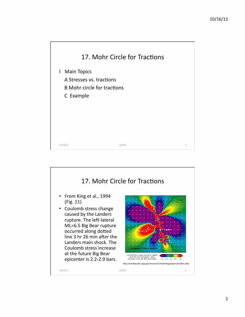
• From King et al., 1994 (Fig. 11)
• Coulomb stress change caused by the Landers rupture. The leP-‐lateral ML=6.5 Big Bear rupture occurred along doTed line 3 hr 26 min aPer the Landers main shock. The Coulomb stress increase at the future Big Bear epicenter is 2.2-‐2.9 bars.
10/16/11 GG303 2
hTp://earthquake.usgs.gov/research/modeling/papers/landers.php
10/16/11
2
17. Mohr Circle for Trac4ons
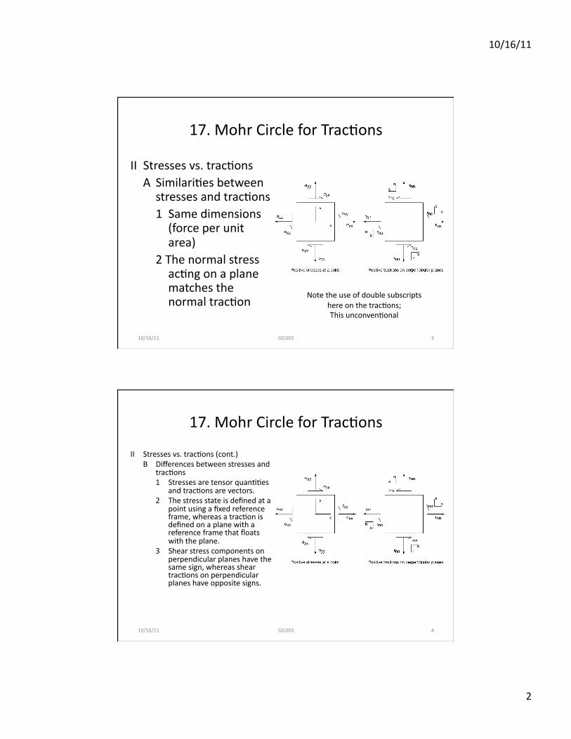
II Stresses vs. trac4ons A Similari4es between stresses and trac4ons 1 Same dimensions (force per unit area)
2 The normal stress ac4ng on a plane matches the normal trac4on
10/16/11 GG303 3
Note the use of double subscripts here on the trac4ons; This unconven4onal
17. Mohr Circle for Trac4ons II Stresses vs. trac4ons (cont.)
B Differences between stresses and trac4ons 1 Stresses are tensor quan44es
and trac4ons are vectors. 2 The stress state is defined at a
point using a fixed reference frame, whereas a trac4on is defined on a plane with a reference frame that floats with the plane.
3 Shear stress components on perpendicular planes have the same sign, whereas shear trac4ons on perpendicular planes have opposite signs.
10/16/11 GG303 4
10/16/11
3
17. Mohr Circle for Trac4ons
III Mohr circle for trac4ons A B Now
C
D
10/16/11 GG303 5
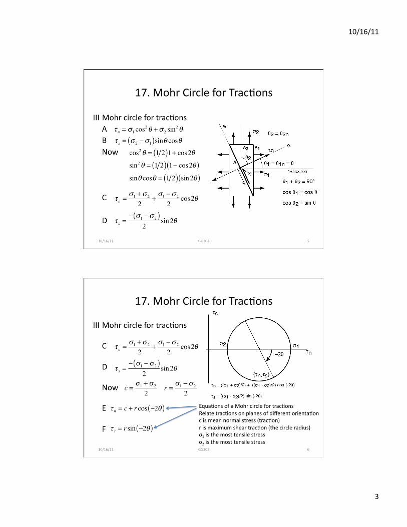
τ n = σ1 cos2θ +σ 2 sin
2θτ s = σ 2 − σ1( )sinθ cosθ
cos2θ = 1 2( )1+ cos2θsin2θ = 1 2( ) 1− cos2θ( )sinθ cosθ = 1 2( ) sin2θ( )
τ n =σ1 +σ 2
2+σ1 − σ 2
2cos2θ
τ s =− σ1 − σ 2( )
2sin2θ
17. Mohr Circle for Trac4ons
III Mohr circle for trac4ons
C
D
Now
E
F
10/16/11 GG303 6
τ n =σ1 +σ 2
2+σ1 − σ 2
2cos2θ
τ s =− σ1 − σ 2( )
2sin2θ
c = σ1 +σ 2
2r = σ1 − σ 2
2
τ n = c + r cos −2θ( )
τ s = r sin −2θ( )
Equa4ons of a Mohr circle for trac4ons Relate trac4ons on planes of different orienta4on c is mean normal stress (trac4on) r is maximum shear trac4on (the circle radius) σ1 is the most tensile stress σ2 is the most tensile stress
10/16/11
4
17. Mohr Circle for Trac4ons
III Mohr circle for trac4ons
C
D
Now
E
F
10/16/11 GG303 7
τ n =σ1 +σ 2
2+σ1 − σ 2
2cos2θ
τ s =− σ1 − σ 2( )
2sin2θ
c = σ1 +σ 2
2r = σ1 − σ 2
2
τ n = c + r cos −2θ( )
τ s = r sin −2θ( )
Equa4ons of a Mohr circle for trac4ons Relate trac4ons on planes of different orienta4on c is mean normal stress (trac4on) r is maximum shear trac4on (the circle radius) σ1 is the most tensile stress σ2 is the most tensile stress
17. Mohr Circle for Trac4ons
10/16/11 GG303 8
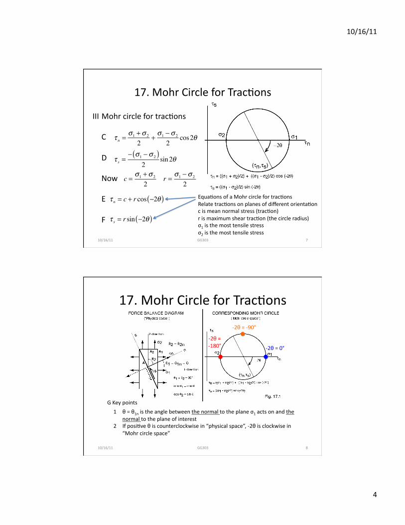
1 θ = θ1n is the angle between the normal to the plane σ1 acts on and the normal to the plane of interest
2 If posi4ve θ is counterclockwise in “physical space”, -‐2θ is clockwise in “Mohr circle space”
G Key points
-‐2θ = 0°
-‐2θ = -‐90°
-‐2θ = -‐180°
10/16/11
5
17. Mohr Circle for Trac4ons
Example 1 using Mohr circle to find principal stresses • Suppose σxx = +10 MPa (tension), σxy = +3 MPa (le: lateral shear), σyy = +2 MPa
(tension), and σyx = +3 MPa (right lateral shear). A) Draw a box in a reference frame and clearly label the stresses on its sides; this is a
criBcally important step. B) Determine the stresses and trac4ons on the faces of the box. Here, we use the
tensor "on-‐in" conven4on.
10/16/11 GG303 9
17. Mohr Circle for Trac4ons
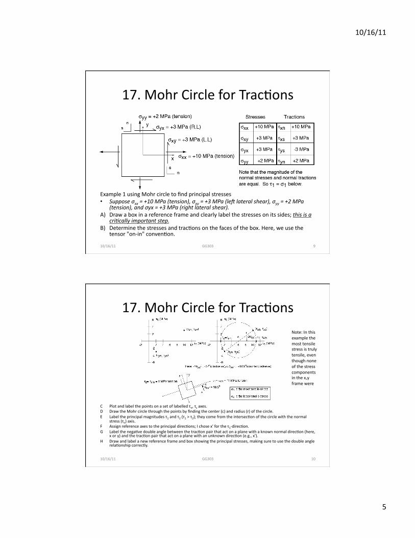
C Plot and label the points on a set of labelled τn, τs axes. D Draw the Mohr circle through the points by finding the center (c) and radius (r) of the circle. E Label the principal magnitudes τ1 and τ2 (τ1 > τ2); they come from the intersec4on of the circle with the normal
stress (τn) axis. F Assign reference axes to the principal direc4ons; I chose x' for the τ1-‐direc4on. G Label the nega4ve double angle between the trac4on pair that act on a plane with a known normal direc4on (here,
x or y) and the trac4on pair that act on a plane with an unknown direc4on (e.g., x'). H Draw and label a new reference frame and box showing the principal stresses, making sure to use the double angle
rela4onship correctly.
10/16/11 GG303 10
Note: In this example the most tensile stress is truly tensile, even though none of the stress components in the x,y frame were