Embed Size (px)
DESCRIPTION
catv
Citation preview

CATV NETWORKS

Today’s cable systems serve up more than just television. Because community antenna television (CATV) systems now incorporate high-speed data and telephony services, signal flow is critical for multiple systems operators (MSOs) and their customers. Signal levels and network configurations must evolve to meet the new service demands of transitioning headends. The impending challenge for MSOs is to effectively manage their networks amid change and maintain maximum uptime for subscribers.

Early CATV systems consisted of television signals combined at the headend and delivered to subscribers via a coaxial cable network. Signals were transmitted from the headend to the subscriber and provided entertainment and information only—vital "lifeline" telephony or data services were not offered. The assurance of uninterrupted service was a distant priority. Repairs, replacements, and upgrades were performed at the convenience of the operator. System outages were common, and generally tolerated, if limited to short periods of time.The inclusion of advanced services has forced MSOs to develop networks that can deliver uninterrupted service. CATV RF signal management breakthroughs have proven paramount in the evolution to nonintrusive networks.
BACKGROUND
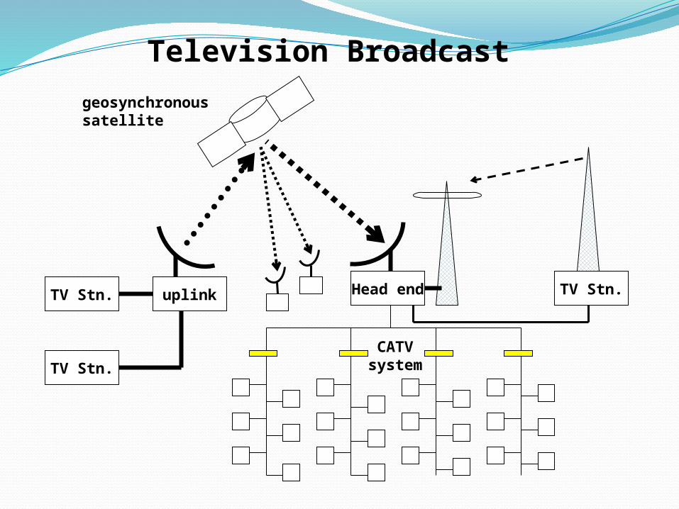
Television Broadcast
Head endTV Stn. uplink
TV Stn.
TV Stn.
geosynchronoussatellite
CATVsystem

Space (satellite)
Terrestrial (wire & fiber)
Otherhigh-speed
PSTNwireless
CATVco-ax
PSTNtwisted pair
WideArea
Network
The Last Mile
These are not separate systems: they are all interconnected, sharing infrastructure. One WAN channel may be carrying voice, video and data at the same time, for different users, and different carriers (telephone/cable companies).
indiv-idual
LAN/ISP/
OLTPPBX B’cast

Cable Modems
• Coax cables from several neighborhoods connect to a concentrator– The concentrator uses high capacity fiber optics
cables to connect to the head end, which is connected to the Internet.
• Communication is asymmetric– Originally, CATV was designed only for
downstream communication!• Available bitrates:
– Downstream: 1.5 to 2 Mb/s– Upstream: 128 kb/s

Cable Modems• CATV (Community Antenna TV, or cable TV)
uses coax cable (less susceptible to interference)– 1-Km coax cable can accommodate bitrates of 1-2 Gb/s!
• Only one cable is used for a neighborhood– Different TV channels are multiplexed on it.
• Cable systems are designed to carry many more television signals than currently available.– There is unused capacity that can be used for
data communication!– >80% of US homes are already reached by CATV

Cable Modems (cont’d)
• User can connect using a cable modem– A splitter separates the TV and the data signals.
• Problem: all users in the neighborhood share the same available capacity in the same cable!– If all users in the neighborhood transmit data at
the same time, the available bitrate is reduced.• E.g., if there are 50 Mb/s available, and 100 users in the
neighborhood use it simultaneously, each user has only 0.5 Mb/s

Cable Modem OutlineTwo channels from cable TV
provider dedicated to data transferOne in each direction
Each channel shared by number of subscribersScheme needed to allocate capacity
Statistical TDM

Cable Modem OperationDownstream
Cable scheduler delivers data in small packetsIf more than one subscriber active, each gets
fraction of downstream capacity May get 500kbps to 1.5Mbps
Also used to allocate upstream time slots to subscribers
UpstreamUser requests timeslots on shared upstream channel
Dedicated slots for thisHeadend scheduler sends back assignment of future
time slots to subscriber

Cable Modem Scheme


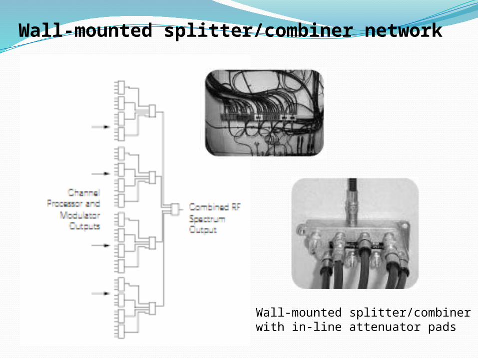
Wall-mounted splitter/combiner network
Wall-mounted splitter/combiner with in-line attenuator pads

Rack-mounted splitter/combiner within-line attenuators
Applications of modular rack-mountedsplitting/combining
RACK MOUNTED NETWORK

Sketch of modular combiner with front-mounted attenuation pads
The Next Evolutionary Stage: Carrier ClassAdvanced cable services now rival the traditional service offerings of the telecommunications industry.In addition to television program delivery, CATV offers high-speed data and voice (telephony, dial tone) service. These advanced networks require highly-reliable and always-available network service.One steadfast technology—used for decades in telecommunications—has been incorporated into today’s cable networks to revolutionize the communications industry. Hitless technology ensures that service remains uninterrupted during maintenance or access operations. High-speed digital circuits (T-1/E-1 and T-3/E-3) have access points within the path of the circuit that can be used for testing, crossconnection, and interconnection.

Circuit termination panels provide access jacks that are installed into the path of a high-speed digital circuit. These jacks accept patch cords that connect circuits and network elements to perform switching functions. Patch cords also enable test equipment to be hooked up directly to the circuit for monitoring purposes. When a patch plug attached to the end of the patch cord is inserted into the jack, signal flow is maintained until the patch plug breaks the flow and routes the signal to the intended destination.

Every maintenance task performed on an advanced communications network has the potential for service interruption. Many business operations rely on CATV high-speed data connections for their daily functions. Residential subscribers also use cable for the bulk of their communication, including emergencies. Service availability is critical.

Not all CATV maintenance is performed at the headend. Some maintenance resides at the outside distribution plant (OSP). Fiber and coaxial cable must be installed to connect new signal paths from the subscriber to the headend and to balance the CATV spectrum before subscribers are connected and service established. Upgrades to OSP systems involve maintenance on existing, service-carrying networks, but the proper technology can minimize downtime and maintain signal transmission.
Reconfiguration with Minimal Signal Interruption

Reconfiguration of existing low-bandwidth nodes and amplifiers with new broadband models introduces a brief service outage during the replacement process. This "node splitting" involves adding new nodes to deliver services to a given set of homes passed, reducing the number of homes serviced on each node.Node splitting establishes new fiber connections from the headend to the OSP by installing nodes in strategic OSP locations within the distribution area, rerouting the coaxial feeder cable to the new nodes, and balancing the spectrum

To properly coordinate with the OSP network, headend systems must also undergo changes. New fiber distribution frames are added, along with new laser transmitters and return path receivers. The reconfiguration of the electrical RF splitting/combining networks, in both forward and return directions, is critical during this transition. Splitters and combiners must be added, removed, or changed. With a variety of configurations (1x8, 1x4, and 1x2) to choose from, operators should have little difficulty finding one to accommodate network requirements. Attenuation pads and equalizers should be mounted on the front of modules to allow easy access in rack-mounted environments. Broadband spectrum signal levels change with every modification, requiring re-balancing during the system re-engineering project.

QOUTE OF THE DAYInsan Gunah Kerne Ki Waja Se Jahanum Mein Nhi Jata Bal Keh Gunah Per Mutmaen Rehny Aur Tauba Na Krney Ki Waja Se Jahanum Mein Jata Hy.