Embed Size (px)
Citation preview
1
Lect - 8
2Prof. Bhaskar Roy, Prof. A M Pradeep, Department of Aerospace, IIT Bombay
Lect - 8
Axial Flow Compressor
3-D Blade Design Laws

3Prof. Bhaskar Roy, Prof. A M Pradeep, Department of Aerospace, IIT Bombay
Lect - 8
12
Cw . r = constant.
This condition is commonly known as Free Vortex Design Law
From Radial Equilibrium Condition and using some simplifying flow conditions (constant H, Ca, ρ along the radius) we get :
4Prof. Bhaskar Roy, Prof. A M Pradeep, Department of Aerospace, IIT Bombay
Lect - 8
The simple Radial Equilibrium may be used to explain some of the basic characteristics of an axial compressor
• Radial equilibrium requires that in a medium (<1.0) to low (« 1.0) hub/tip radius ratio in a rotor blade, change of whirl component (ΔCwor ΔVw ) must be very large near the hub (root) compared to that near the casing (tip)
5Prof. Bhaskar Roy, Prof. A M Pradeep, Department of Aerospace, IIT Bombay
Lect - 8
• Radial equilibrium, thus, requires that flow turning at hub Δβ must be much larger at hub than at the tip.
• Hence hub airfoil must be of much higher camber than that of the tip airfoil
• Whirl component downstream of the rotor (Cw2 or Vw2) is higher than the upstream
6Prof. Bhaskar Roy, Prof. A M Pradeep, Department of Aerospace, IIT Bombay
Lect - 8
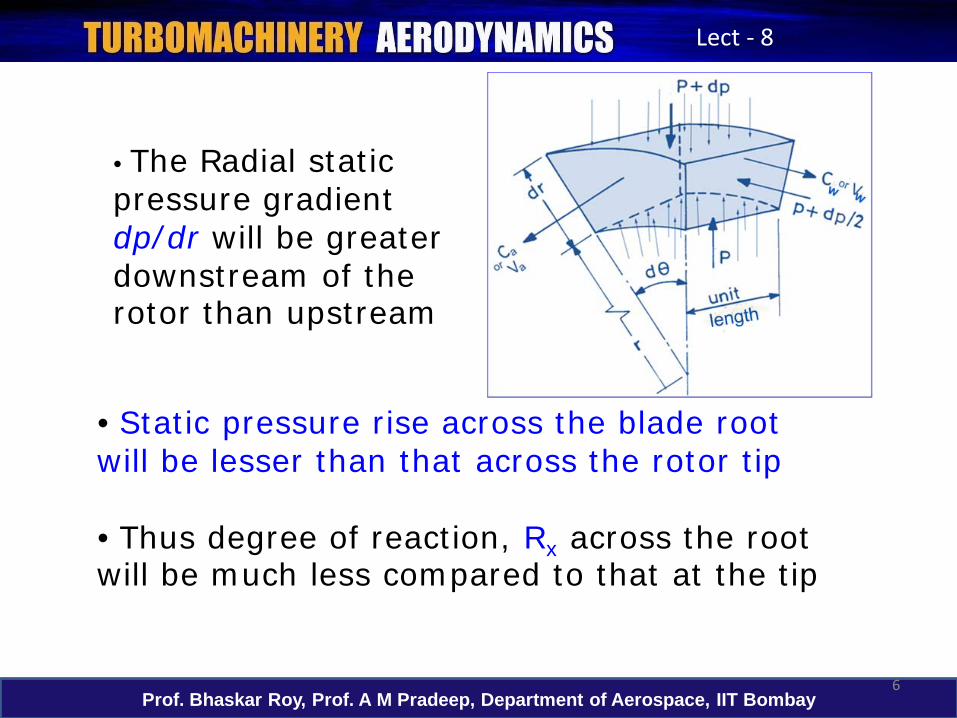
• Static pressure rise across the blade root will be lesser than that across the rotor tip
• Thus degree of reaction, Rx across the root will be much less compared to that at the tip
• The Radial static pressure gradient dp/dr will be greater downstream of the rotor than upstream
7Prof. Bhaskar Roy, Prof. A M Pradeep, Department of Aerospace, IIT Bombay
Lect - 8
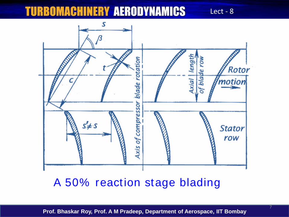
A 50% reaction stage blading
8Prof. Bhaskar Roy, Prof. A M Pradeep, Department of Aerospace, IIT Bombay
Lect - 8
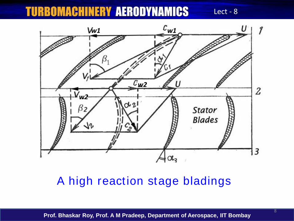
A high reaction stage bladings
w1 w1
w2
w2
9Prof. Bhaskar Roy, Prof. A M Pradeep, Department of Aerospace, IIT Bombay
Lect - 8
• If one looks at a stage consisting of a rotor and a stator, the radial equilibrium would also impact the flow across the stator
• Stator blade rows reduce the whirl component
• Downstream of stator radial pressure gradient dp/dr will be much lower than upstream of the stator
• Static pressure rise, Δp across the stator at hub would be higher than at the tip. This may lead to high blade loading and even flow separation at stator hub
10Prof. Bhaskar Roy, Prof. A M Pradeep, Department of Aerospace, IIT Bombay
Lect - 8
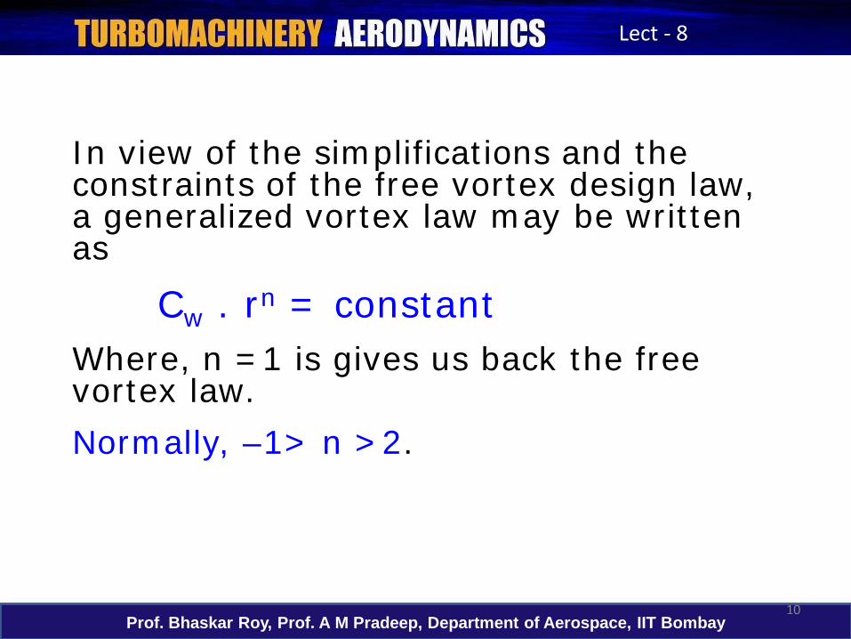
In view of the simplifications and the constraints of the free vortex design law, a generalized vortex law may be written as
Cw . rn = constant Where, n =1 is gives us back the free vortex law.Normally, –1> n >2.
11Prof. Bhaskar Roy, Prof. A M Pradeep, Department of Aerospace, IIT Bombay
Lect - 8
• when 0.75< n ≤ 1.0 it yields near-
free vortex or relaxed-free-vortex
designs in which the blade sections are
slightly overloaded with respect to free
vortex blade loading.
12Prof. Bhaskar Roy, Prof. A M Pradeep, Department of Aerospace, IIT Bombay
Lect - 8
• when n>1 the blades are underloadedw.r.t. FVD law;
• n = -1 is rarely used - often known as the forced vortex design
• n = 0 is known as the Exponential design law and often is used to arrive at constant degree of reaction blade designs
13Prof. Bhaskar Roy, Prof. A M Pradeep, Department of Aerospace, IIT Bombay
Lect - 8
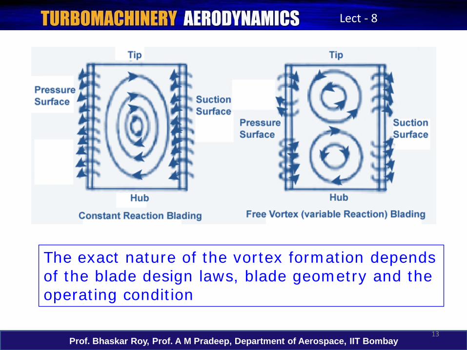
The exact nature of the vortex formation depends of the blade design laws, blade geometry and the operating condition
14Prof. Bhaskar Roy, Prof. A M Pradeep, Department of Aerospace, IIT Bombay
Lect - 8
Preliminary blade designs are also driven by the radial variation of the degree of reaction along the blade length
Three limiting possibilities are often started with:
Rx = 0%Rx = 50%Rx = 100%
50% reaction means diffusion and hence blade loading is equally shared by the rotor and stator
15Prof. Bhaskar Roy, Prof. A M Pradeep, Department of Aerospace, IIT Bombay
Lect - 8
• In case when the degree of reaction is much different from 50%, one of the blades, either rotor or stator is more loaded.
•The two limiting cases are 0% and 100% reaction split between the rotor and the stator.
• As we have seen the reaction may vary from the root to the tip (as in Free Vortex designs)
• Which means the split between the rotor and the stator vary from the root to the tip of a stage
16Prof. Bhaskar Roy, Prof. A M Pradeep, Department of Aerospace, IIT Bombay
Lect - 8
• In Rx = 0% case entire diffusion happens in stator and rotor is used for flow energization. Such a rotor will not have any diffusion occurring in the rotor blade passage, and may be called an impulse rotor (as energy transfer happens due to flow turning). A supersonic rotor may have Rx=0%
• in Rx = 100% case entire diffusion happens in the rotor along with flow energization. The stator is used only for flow turning
17Prof. Bhaskar Roy, Prof. A M Pradeep, Department of Aerospace, IIT Bombay
Lect - 8
Compulsions of these choices are often present depending on whether one is designing a:
i) Small sized axial compressorii) Large sized axial fan (in a bypass turbofan)iii) First stage of a multi-stage axial compressoriv) Middle stage of a multi-stage compressorv) End stage of a multi-stage compressorvi) High hub/tip radius ratio stagevii) Low hub/tip radius ratio stage

18Prof. Bhaskar Roy, Prof. A M Pradeep, Department of Aerospace, IIT Bombay
Lect - 8
Axial Distribution of the specific work (Wth) and efficiency (ηi) amongst the individual stages of a typical multi-stage compressor must be completed and are arrived at from early design choices :
Initial Stages Middle stages Last stages
η 0.86 0.92 0.88
π 1.5-1.8 1.3-1.4 1.1-1.2
∆T0oC 40-75 30-50 15-30
The radial distribution of these parameters are then taken up for each stage design
19Prof. Bhaskar Roy, Prof. A M Pradeep, Department of Aerospace, IIT Bombay
Lect - 8
In the modern axial compressor designs the 3-D flow features inevitably present are:
• Radial variation of Mach number and Reynolds number• Consequently radial variation of density and pressure gradients• Radial variation of blade thickness due to Mach number variation• Radial variation of work input• Hub or casing geometry introducing radial flow• Leakage at the tip and axial gaps• Air bleed in an intermediate stage
20Prof. Bhaskar Roy, Prof. A M Pradeep, Department of Aerospace, IIT Bombay
Lect - 8
• Secondary flow development is a consequence of all the earlier points and the operating point• Some non-uniformity in the inlet flow• Combination of subsonic and supersonic flow
• Radial variation of all the design parameters is high for low hub/tip radius ratio stage, which have high aspect ratio (h/c >2.0)
• Radial variation of parameters is less in a high hub/tip ratio blade e.g. in the last stages, which have low aspect ratios (h/c<2.0)
21Prof. Bhaskar Roy, Prof. A M Pradeep, Department of Aerospace, IIT Bombay
Lect - 8
Next Lecture ----
3-D flow in full mathematical form
More detailed discussion on Compressor Blade Design in a later lecture