Embed Size (px)
Citation preview

L e a v i n g C e r t i f i c a t e
Technology
Control Technology
P I C A X E 1 8 X


Prog. 1………………………………………………….SOUND Output
Prog. 3 …………………………………………………OUTPUT & WAIT
Prog. 6 …………………………………………………LOOP
Prog. 7 ………………………………………………...Seven Segment Display
Prog. 8 ………………………………………………...Single Traffic Light Sequence
Prog. 9 ………………………………………………...Double Traffic Light Sequence
Prog. 10 ……………………………………………....Decision / Digital Input
Prog. 11 ……………………………………………....Motor / Buzzer Control
Prog. 12 ………………………………………………Forward / Reverse Motor Control
Prog. 13 ………………………………………………AND gate
Prog. 14 ………………………………………………OR gate
Prog. 15 ………………………………………………NAND gate
Prog. 16 ………………………………………………OUT
Prog. 17 ………………………………………………PROCEDURE
Prog. 19 ………………………………………………EXPRESS & INC
Prog. 20 ………………………………………………COMPARE
Prog. 21 ………………………………………………Exercise
Prog. 22 ………………………………………………RANDOM number
Prog. 23 ………………………………………………INTERRUPT
Prog. 24 ………………………………………………Analogue Sensors - LDR
Prog. 25 ………………………………………………Variable Resistor
Prog. 26 ………………………………………………Temperature
1 © t4 Galway Education Centre
Before using this package ensure that you have selected the correct software.
The following courseware assumes the use of PIC Logicator 2006. Go to PIC,
select PIC type, and choose the PICAXE18X. This is the preferred PIC device
and having 5 inputs and 8 outputs can be used for a wide array of classroom
based projects.
PROG.1 – ‘SOUND’ command
Drag each command from the right hand side
of your screen. Click and hold down the left
mouse button to drag in each command. The
second cell makes use of the sound
command. Double click the left button on the
sound command. This will open a window and
allow you to select a sound value. Scroll or
type to enter the selected value, set pin 3 as output and set the note to E4. You
can set the duration of the note by placing a value in the time box i.e. 0.75s.
Select the drawing tool icon, this shows as a pencil, right click where you want
the line to begin; then right click where you want the line to end. Click the green
arrow to RUN and test.
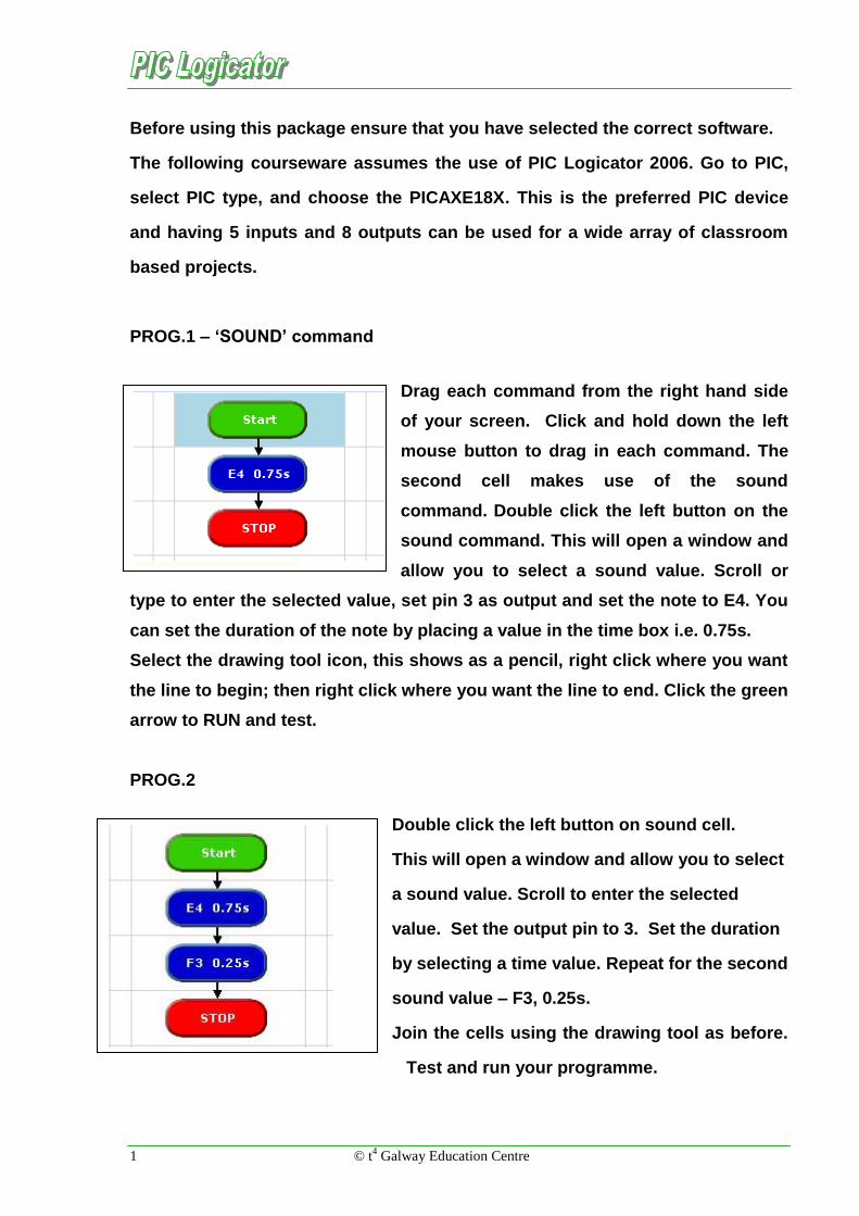
PROG.2
Double click the left button on sound cell.
This will open a window and allow you to select
a sound value. Scroll to enter the selected
value. Set the output pin to 3. Set the duration
by selecting a time value. Repeat for the second
sound value – F3, 0.25s.
Join the cells using the drawing tool as before.
Test and run your programme.
© t4 Galway Education Centre 2
PROG.3 – ‘OUTPUT’ & ‘WAIT’ command
WAIT is used to set the length of time the lamp / LED is turned on. WAIT is set
using seconds or fractions of a second e.g. 2 seconds in this case.
‘LED ON’ is called a label. Note however it is the setting on the output line
using the bit pattern 0000 0001 which causes the LED to turn on – NOT the
label.
PROG.4
Note that in the cell LEDs ON both LEDs will light. The WAIT command
instructs that the LEDs should remain on for 3 seconds. The program then
moves to the SOUND cell. The LEDs do not turn off at this point but remain on.
If we wish the LEDs to be turned off then we must instruct them to be turned off
by setting the outputs to 0000 0000. In this case the STOP command turns off
all outputs.
Outputs are used to turn LEDs,
light bulbs or other outputs on
and off. Note that the PIC cannot
switch bulbs directly but must
use a driver circuit (in most
cases – a transistor)
Placing a light bulb in O
It is possible to turn on a number
of outputs at the same time by
setting the correct ‘bits’. Each bit
controls one output. In this case
two LEDs are driven from output 0
and output 1. The yellow comment
boxes are useful as they allow us
to see how the outputs are set.

3 © t4 Galway Education Centre
The ‘OUTPUT’ command – Bit Configuration
There are three settings that can be
used when setting Outputs.
(a) Let us look at Bit 0 – in this case it
has been set to 1 or ON.
(b) Bit 0 has now been set to 0 which
means that the output is switched
OFF.
(c) There is a third state to which BIT 0
can be set. This is represented by a
dash as shown below. Care must be
taken if you choose to use this option.
The dash is used as a ‘doesn’t matter’
state. This means that the output will
not change from where it was set
previously. If it was on then it will
remain on and if it were off then it
remains off. This can lead to
confusion – set all bits to either 1 or 0.

© t4 Galway Education Centre 4
PROG.5
This program turns on two outputs
to which LEDs are connected. Can
you follow the sequence through?
Remember we must tell the
program which pin is connected to
the piezo sounder i.e. pin 3, as this
pin is pulsed on and off and not
simply switched on as is the case
in an LED.
PROG. 6 – ‘LOOP’ command
The program shown
will cause both LEDs
to flash on and off
forever. This is
achieved by using the
loop back to the start
of the program. This is
really useful as many
procedures in real life
run continually. These
include automated drilling of PCB boards or traffic light sequences which run
forever. The advantages of using the PIC should start becoming obvious. If we
need to change the sequence or part of the sequence (e.g. change the wait to 1
second) we simply rewrite the software, not remake the circuit.

5 © t4 Galway Education Centre
PROG.7 - Seven Segment Display
It is possible to control a seven segment display using your control board.
Each segment of the display is in fact an LED. What we must do therefore is
work out which LED is controlled by which bit. Note that the bits are numbered
0-7 and this can sometimes lead to confusion.
Controlled by bit ____
Controlled Controlled by bit ____
Now that we know which segment is controlled by each bit it is possible to
design a program that will allow us to count from 0 to 9. If we include a 1
second delay in the program it is possible to make a stopwatch. In the case of
connecting to the PIC note that we can control each segment of the LED
directly, as it only requires 5-10mA. When ordering, ensure the 7 segment
display is the common cathode type.
a
b
c
d
e
f
a
b
c
d
e
f
a
b
c
d
e
f
a
b
c
d
e
f
Controlled by bit ____
a
b
c
d
e
f
Controlled by bit ____ Controlled by bit ____
a
b
c
d
e
f
Controlled by bit _____ Controlled by bit ____
a
b
c
d
e
f
The image opposite,
found on your control
board, should prove
really useful!! Can
you see that output 0
controls the ‘a’ etc.
© t4 Galway Education Centre 6
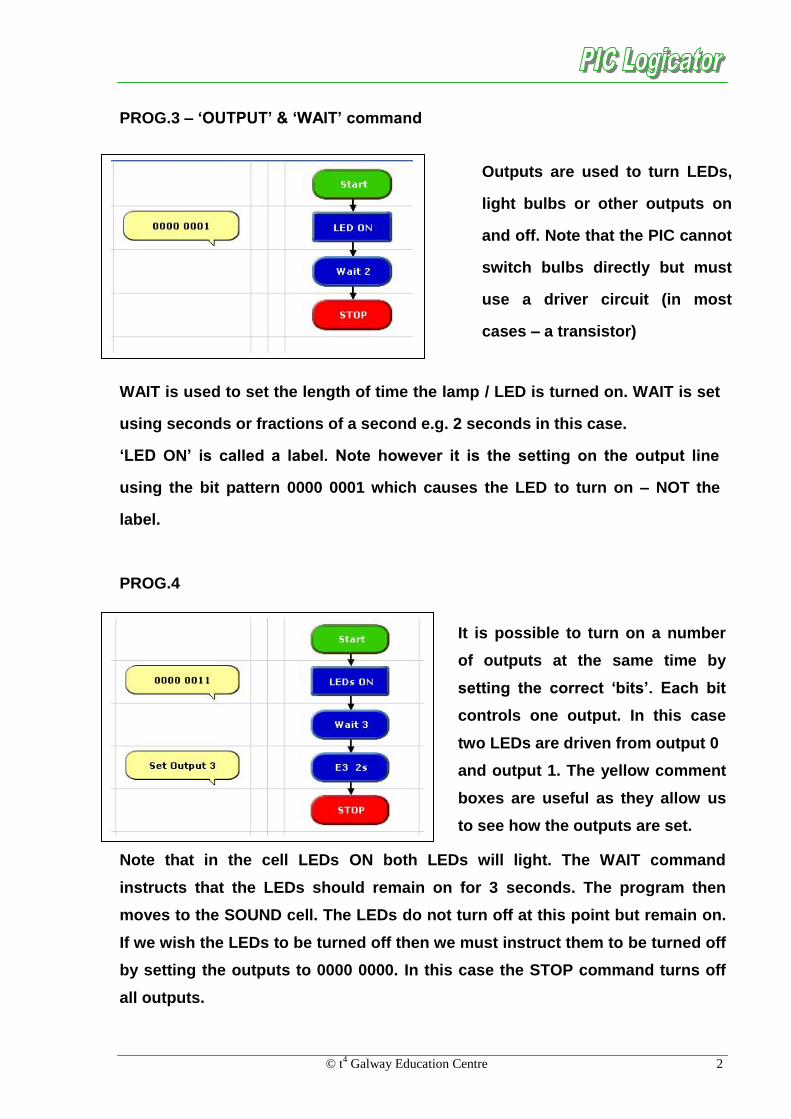
PROG.8 – Single Traffic Light Sequence
Shown above is the sequence of lights on a single traffic light. Write a program
that will follow this sequence and repeat forever.
Step – 1 (Bit pattern) _ _ _ _ _ _ _ _
Step – 2 (Bit pattern) _ _ _ _ _ _ _ _
Step – 3 (Bit pattern) _ _ _ _ _ _ _ _
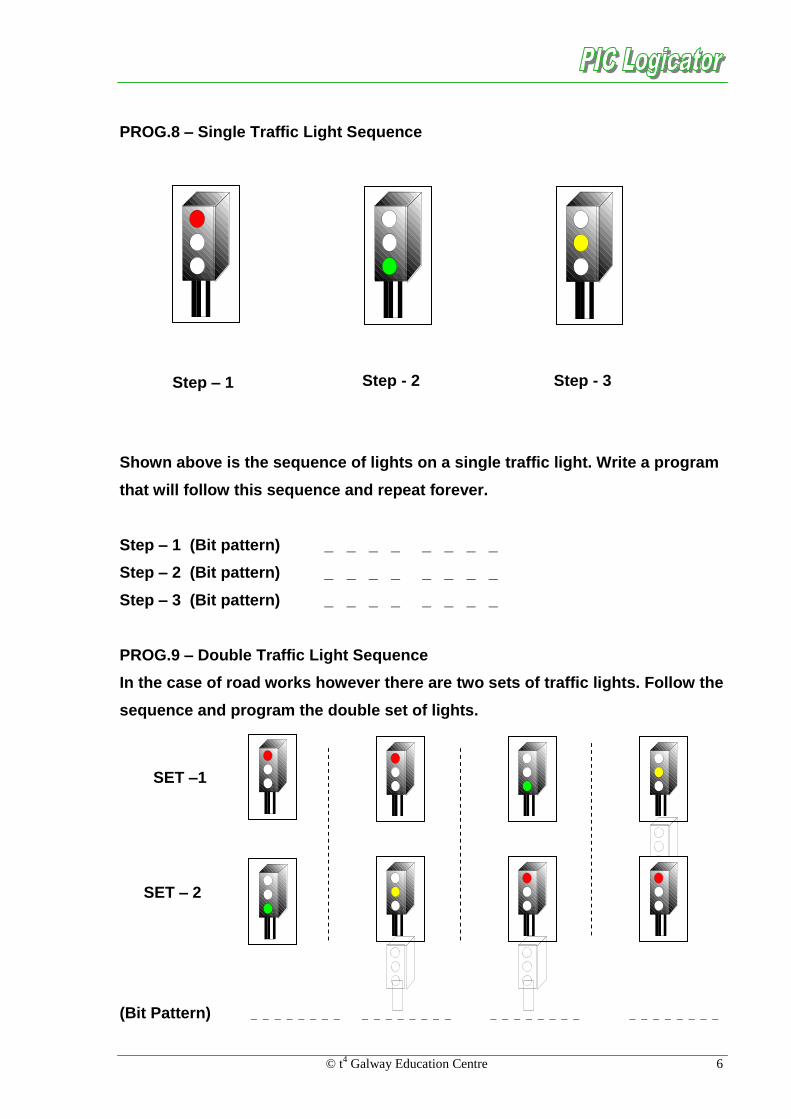
PROG.9 – Double Traffic Light Sequence
In the case of road works however there are two sets of traffic lights. Follow the
sequence and program the double set of lights.
(Bit Pattern) _ _ _ _ _ _ _ _ _ _ _ _ _ _ _ _ _ _ _ _ _ _ _ _ _ _ _ _ _ _ _ _
Step – 1 Step - 2 Step - 3
SET –1
SET – 2

7 © t4 Galway Education Centre
PROG.10 – ‘DECISION’ command
In real life as well as processes which run continually
there are times when user input is necessary.
Nowadays however there is a tendency to automate the
process in response to changes in light, temperature,
liquid level or other stimuli. So far we have used the PIC
to drive outputs such as LEDs and Piezo sounders. The
real value of control technology is when outputs are
driven or controlled by the input conditions.
On your control board, five inputs are included. The
inputs are labelled as shown, the reason for this will be
covered later. Let us begin by redesigning a previous
program to include a switch (Input 7) used as an input.
How do I set an input? Well this is quite
easy really, once you begin to understand
decisions boxes. By dragging in a decision
box and clicking on it, the window
opposite opens. You can see there are
only five inputs available and that the
numbers correspond with the diagram
above. One thing you must understand is
that when switch seven has not been
pressed the voltage at input 7 is 0V or low. In digital terms we say that when
not pressed Input 7 is a zero (0). When the switch is pressed, input 7 goes to 5
volts or high. We say it is now a one (1). The dashes mean we are ignoring the
other inputs, looking only at Input 7. By using this syntax we are really asking
a question and as a result making a decision. Has the switch which is
connected to input 7 been pressed? If the answer is yes carry out this
instruction, if not do this. Please note that it is not the label which determines
the decision but rather which inputs are set to 1 or 0.

© t4 Galway Education Centre 8
Please ensure that you use a decision box and not a compare box which
performs a different function. Remember to set input 7 to a 1 or high as shown
previous. When you start the program nothing happens until the switch (Input
7) is pressed. When the switch is not pressed the decision box will continually
‘ask’ has the switch been pressed and on finding the answer is No it will follow
this route out of the decision box and back in again.
On the other hand when the switch has been pressed and Input 7 is in fact 1
then the answer to the question is now positive and the Yes route is followed.
This means that the LEDs will be turned on for two seconds and so on.
Note that when completed the program returns to the decision box awaiting the
next press of the switch.
Please note.
Understanding the operation of a decision box is vital to maximizing the
use of control technology. Do not progress until you have a full
understanding of the previous program.

9 © t4 Galway Education Centre
PROG.11 – Motor / Buzzer Control
To control a motor or buzzer we connect either
component in the position shown. These
treminals blocks are found to the right hand
edge of the control board. One end of the motor
or buzzer must be connected to the positive
supply, V+, and the other to one of the outputs
0, 1, 2 or 3.
The program opposite shows how
we are using input 6 which is a
tactile switch. Again when not
pressed the input is 0 but 1 when
pressed. Input 6 therefore is set
to look for a 1 when pressed.
Two further points to note:
The label used this time is ‘Six?’
Remember the label is irrelevant,
rather if the inputs are set to
check for 0 or 1.
Secondly note that the program does not loop to the start again but only runs
once. Note also that we did not turn off the motor as this happens
automatically when the stop command is reached.
© t4 Galway Education Centre 10
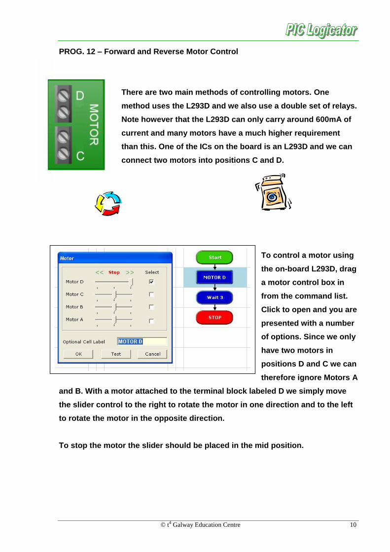
PROG. 12 – Forward and Reverse Motor Control
There are two main methods of controlling motors. One
method uses the L293D and we also use a double set of relays.
Note however that the L293D can only carry around 600mA of
current and many motors have a much higher requirement
than this. One of the ICs on the board is an L293D and we can
connect two motors into positions C and D.
To control a motor using
the on-board L293D, drag
a motor control box in
from the command list.
Click to open and you are
presented with a number
of options. Since we only
have two motors in
positions D and C we can
therefore ignore Motors A
and B. With a motor attached to the terminal block labeled D we simply move
the slider control to the right to rotate the motor in one direction and to the left
to rotate the motor in the opposite direction.
To stop the motor the slider should be placed in the mid position.
11 © t4 Galway Education Centre
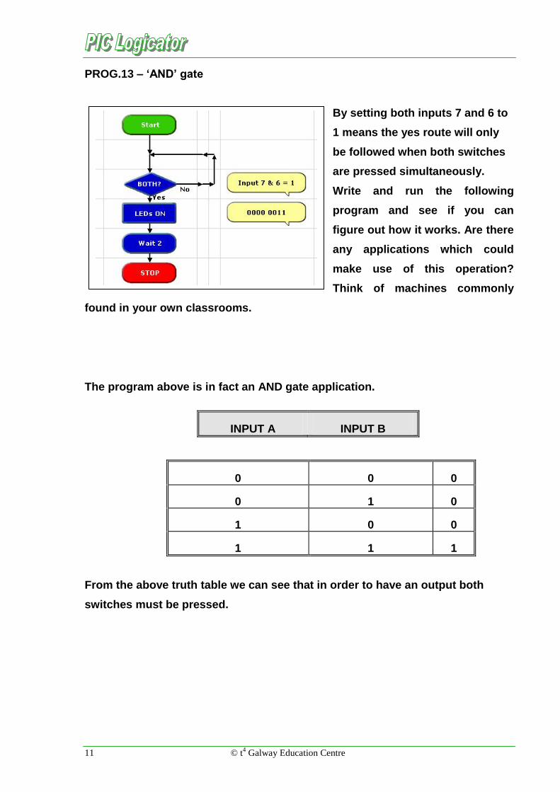
PROG.13 – ‘AND’ gate
By setting both inputs 7 and 6 to
1 means the yes route will only
be followed when both switches
are pressed simultaneously.
Write and run the following
program and see if you can
figure out how it works. Are there
any applications which could
make use of this operation?
Think of machines commonly
found in your own classrooms.
The program above is in fact an AND gate application.
INPUT A INPUT B
0 0 0
0 1 0
1 0 0
1 1 1
From the above truth table we can see that in order to have an output both
switches must be pressed.

© t4 Galway Education Centre 12
PROG.14 – ‘OR’ gate
By building and running the program shown confirm that this behaves as an
OR gate. Complete the truth table below. Note that Input 6 is set to a 1 in the
first decision box and that input 7 is set in the second. Write a paragraph to
explain how this program operates.
0 0 0
0 1
INPUT A INPUT B

13 © t4 Galway Education Centre
PROG.15 – NAND gate
Making good progress? Great, because this one is just a bit more difficult.
Design a program to simulate two switches connected to an NAND gate.
Remember to use inputs 7 and 6 as before. The truth table is shown below.
Check your answer by going through each line of the table.
The solution is given at the end of these notes, don’t even think about it!!
INPUT A INPUT B
0 0 1
0 1 1
1 0 1
1 1 0
PROG.16 – ‘OUT’ command
The OUT command can also be used to control
outputs. It has certain advantages in that a number of
outputs can be controlled simultaneously. Follow the
binary pattern below and we begin to make sense of
how this command works. OUT 1 will switch on the
first output and OUT 2 the second and so on. What
will OUT 3 do? Well, 3 is 2&1 so we switch on the first
two LEDS. Try the following OUT 56, OUT 128, OUT
136 and OUT 220. Can you predict which LEDs will
light before setting the OUT command?
64 32 16 8 4 2 1 128

© t4 Galway Education Centre 14
PROG.17 – ‘PROCEDURE’ command
Procedures are very useful to use in our programs. They are used when there is
a block of code or instructions that are used repeatedly in our program. The
following program shows how the procedure ‘FLASH’ is called five times in the
same program. We use the ‘Do Proc’ command to call a macro and the
‘Procedure’ command to define what it is we wish to do. Note these are two
distinct commands, do not mix them up.
Not only does using the procedure
make the program five lines shorter,
as the commands to make the LEDs
flash on and off are only inserted
once, but the program is much
neater and easier to follow. Use
macros in your program where
possible.
PROG.18
This is a good
example of using
procedures to
reduce the size of
a program. Run
this program and
understand how
it works.

15 © t4 Galway Education Centre
PROG.19 – ‘EXPRESS’ & ‘INC’ command
This program introduces
variables and the INC or
increment command.
Variables are very useful and
are used just as in maths, to
store numbers or values. The
variable we are using is called
‘A’. Using an expression box we
set A = 0 at the start. This is
always good practice. INC is a
command found on the
command list, and we set it to INC variable A. This means that A should
increase in value by 1 every second as we have created a loop with a Wait and
INC command. Before running this program, go to View and select the
Variables Panel. As the program runs we should see the value of A increase by
1 every second.
PROG.20 – ‘COMPARE’ command
It is sometimes useful to be able to
make a process happen a fixed
number of times. A continuos loop
will not allow us to do this, as the
operation will be repeated again
and again. Follow this program
and observe that the sound can be
heard five times.
Note that we do not use a decision
box on this occasion but rather the
compare command.

© t4 Galway Education Centre 16
PROG.21 – Exercise
‘Mars’ chocolate bar company has
decided to release a new family pack
containing seven bars.
Your task is to design a system which
will recognise when seven bars have
passed along the conveyor belt and switch on a motor (Output 1) which will
push the seven bars into their packet. Alert the user that seven bars have been
packaged.
Break the project into a number of smaller tasks.
How will we know when a bar has gone past? (Micro-switch?)
How can we count seven bars? (‘INC’ command)
When seven bars have been counted, switch on a Motor and a Sound to
warn the user.

17 © t4 Galway Education Centre
PROG.22 – ‘RANDOM’ number
Random will generate a random
number from 0 – 255. By using the
variables panel we are able to see
that a random number is generated
each second.
Random will generate any random number from 0 - 255

© t4 Galway Education Centre 18
PROG.23 – ‘INTERRUPT’ command
Consider the case of a lathe or similar machine. All should be fitted with a
switch that will not allow the machine to be restarted until a safety guard is in
place. As soon as the guard is lifted the machine will stop immediately. We
have no way of knowing when the guard might be lifted – this is probably one
of the best ways of describing what happens in the case of an interrupt.
In this case the following program it will turn on a motor and allow the motor to
run until the interrupt has been triggered by pressing the switch (Input 7). The
event is usually triggered by a switch being pressed or released. The program
will return to the wait command when the interrupt commands have been
completed.
The difference between an interrupt and an ordinary decision box is that the
interrupt tests for the condition all the time. In the case of the decision box the
switch is only tested when the program reaches that part of the program.
Each time an interrupt is called the Enable Interrupt command is switched
off, the first thing you should do before when you re-enter the main program
is to turn the event on again.
In the case of the PICAXE18x only one interrupt can be used within a
program.
19 © t4 Galway Education Centre
PROG.24 – Analogue Sensors
Temperature and light are examples of analogue conditions. We have three on-
board analogue sensors:
LDR – Input 0
Potentiometer – Input 1
Digital thermometer – Input 2
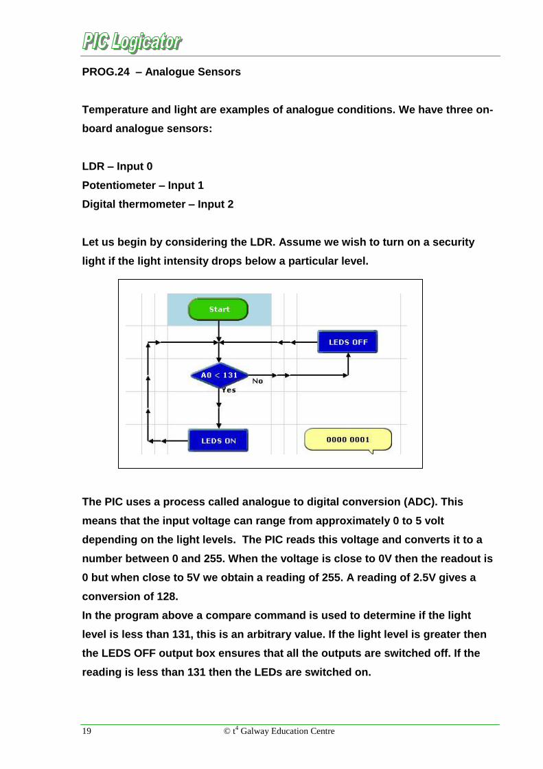
Let us begin by considering the LDR. Assume we wish to turn on a security
light if the light intensity drops below a particular level.
The PIC uses a process called analogue to digital conversion (ADC). This
means that the input voltage can range from approximately 0 to 5 volt
depending on the light levels. The PIC reads this voltage and converts it to a
number between 0 and 255. When the voltage is close to 0V then the readout is
0 but when close to 5V we obtain a reading of 255. A reading of 2.5V gives a
conversion of 128.
In the program above a compare command is used to determine if the light
level is less than 131, this is an arbitrary value. If the light level is greater then
the LEDS OFF output box ensures that all the outputs are switched off. If the
reading is less than 131 then the LEDs are switched on.

© t4 Galway Education Centre 20
PROG.25 – Variable Resistor
A variable resistor is
connected to input 1. The
value of the resistance is used
to switch on a number of
LEDs depending on which
position the variable has been
adjusted to. Slowly rotate the
variable in each direction and
note the reading. Can you see
an application for measuring the amount of oil in a tank at the bottom of the
garden? Hint: Think of a cistern!
There is a second method of checking the position of the variable resistor.
This program makes use of
the ’Serial in’ – pin 3.
Essentially, debug causes a
message to be transmitted
from the PIC back to the
computer screen. This shows
up as a value in the pop-up
window. Both programs
should produce the same
result. To display the pop-up window go to PIC on the main menu and select
‘DEBUG…’ or use Alt + F7.

21 © t4 Galway Education Centre
PROG.26 – Temperature
This program demonstrates the potential for making use of the digital
thermometer which is connected to input 2. Using the ReadTemp we set the
variable A as being equal to the readout from the thermometer. Note that in this
case we do not obtain a reading of between 0 and 255 but rather a reading of
between 10 and 40 degrees
depending on the temperature
of the surroundings.
We then use the OUT
command to cause a number
of LEDS to light. Assume the
room temperature is 17° then
an OUT A would result in the
first and fifth LEDs being lit.
Using the binary scale below
can you understand why it is these two LEDs which are switched on.
64 32 16 8 4 2 1 128

© t4 Galway Education Centre 22
Solutions
When both switches are pressed
the YES route is followed. As
long as both switches are
pressed the program will
continually loop through the
decision box. If either one or
both of the switches are released
then the NO route is followed and
the LEDS are switched on.
128