Embed Size (px)
Citation preview

CADD 121 Engineering Graphics with AutoCAD
SYLLABUS
Revised 17 December, 2002 Lisa E. Beathea


CADD 121 SYLLABUS COURSE DESCRIPTION This course provides a complete Engineering Graphics curriculum executed on a CAD. (Computer Aided Drafting/Design) workstation. The course covers basic Graphic Size and Shape Development, Orthographic Projection, Sectional and Auxiliary views, Dimensioning and Tolerancing, Fasteners, and Working Drawings. COURSE OBJECTIVE An outstanding tool for learning the basics of engineering drawing, AutoCAD 2000 software is used. Featuring problem-solving, step-by-step tutorials, it takes the user from one-view engineering drawings to geometric constructions and multiview projections. Each tutorial follows traditional engineering drawing techniques and methods while showing how to utilize features and benefits of AutoCAD 2000 to achieve professional results. PREREQUISITES It is recommended that the student have taken, or currently be taking DRFT-106 or have had some previous basic drafting experience, either in high school or industry. REQUIRED TEXT Engineering Graphics with AutoCAD®2000 By James D. Bethune, Prentice-Hall, 2000 ISBN. 0-13-022-135-X REQUIRED MATERIALS 3 each 31/2" DSHD Floppy Disks STUDENT PERFORMANCE EVALUATION/PARTICIPATION Active participation in this course by all students is required and expected. Attendance for all lectures is strongly advised.
1. All assigned exercises must be performed according to schedule and submitted within two weeks for grading. Late work may be penalized at the rate of 10% per week late.
2. The progress of the student will be evaluated by class participation, graded assignments, and on time submission of assigned exercises.
3. There will be a minimum of 10 assignments which will constitute 75% of the class grade. There will be a final project that will comprise 25% of the total grade. Students must complete this project to pass the course.
4. Any student whose performance is unsatisfactory or not up to date will be notified by the College and may be dropped from the course for insufficient progress or participation.
If you have a documented disability and would like to request an accommodation and/or academic adjustment, contact the Disability Services Office at (732) 224 2730 or TTY (732) 842 4211.
LEH Page 1 12/17/02

CADD 121 SYLLABUS GRADING The following scale will be used to determine satisfactory progress on each assignment and for determining the final grade based on the following:
LETTER GRADE NUMERICAL GRADE A 90 to 100 B 80 to 89 C 70 to 79 D 65 to 69 F Below 65
You must obtain a grade of C or higher before taking any course for which this is a prerequisite. FINAL GRADE The final grade will be determined by averaging the assigned exercises and combining this average with the final project grade according to the following formula: 75% for the Average of the exercises 25% for the Final Project 100% Grade for the Course
Students must complete Final Project to pass the course. INCOMPLETE It is the student's responsibility to submit all classwork according to schedule and it is expected that all course requirements be completed by the last class meeting. However, in cases of hardship or emergency, a grade of INC may be granted by your instructor. In order to be considered for the grade INC, the student must have satisfactorily completed all assignments except the final project, have a passing average, and must meet with the instructor prior to the last class meeting to discuss this option. Your instructor is under no obligation to grant an INC. In the event that you are granted an INC, it must be completed by the second week of the following semester or an earlier date specified by the instructor.
LEH Page 2 12/17/02

CADD 121 SYLLABUS CORE COMPETENCIES In this course students learn the basics of engineering drawing using a CAD (Computer Aided Drafting/Design) workstation. Students must learn and apply traditional engineering drawing techniques and methods and demonstrate the ability to utilize CAD software to prepare professional quality engineering drawings. This course covers one-view engineering drawings, geometric constructions, multi-view projections, basic graphic size and shape development, orthographic projection, sectional and auxiliary views, dimensioning and tolerancing, fasteners, and working drawings. This course teaches the following Core Competencies:
CRITICAL THINKING, PROBLEM SOLVING Students will use critical thinking and problem solving skills in analyzing information.
2.1 Identify a problem and analyze it. 2.2 Create or develop hypotheses. 2.3 Recognize and construct logical forms of argumentation. 2.4 Recognize and identify examples of faulty ways of reasoning.
MATHEMATICAL SKILLS Students will apply appropriate mathematical concepts and operations to interpret data
and to solve problems, and to understand connections between mathematics and other disciplines.
4.1 Be able to analyze, discuss and use quantitative information. 4.2 Be able to apply algebraic and/or geometric techniques to analyze and
solve mathematical problems. 4.3 Use appropriate problems solving technologies.
SCIENTIFIC PERSPECTIVE
Students will develop a familiarity with the principles and methods of scientific inquiry, and with its significance to society.
5.1 Develop appropriate skills in observation and experimentation to solve problems.
5.2 Be able to analyze and interpret scientific data. 5.3 Be able to evaluate and apply appropriate technology.
INFORMATION AND TECHNOLOGICAL LITERACY
Students will process information including defining, accessing, gathering, organizing, evaluating, and presenting information.
7.1 Recognize a need for information. 7.2 Conduct and complete effective research. 7.3 Access, use, document and present information objectively and
effectively. 7.4 Use appropriate technologies and services to access and process
information.
LEH Page 3 12/17/02

CADD 121 SYLLABUS ACADEMIC INTEGRITY
Academic integrity is submitting one's own work, and properly acknowledging the work of others. Any violation of this principle constitutes academic dishonesty and is liable to result in disciplinary action. Forms of academic dishonesty include:
Plagiarism Submitting another person’s work, in whole or part, as one's own. This includes an examination, a computer program, a laboratory report, or a written assignment. Facilitating Academic Dishonesty Helping another commit an act of dishonesty, such as substituting for an examination or completing an assignment for someone else. Cheating Using or attempting to use unauthorized materials on an examination or assignment, such as using unauthorized texts or notes or improperly obtaining, or attempting to obtain, copies of an examination or answers to an examination. Illegal System Access Altering, transmitting, or permitting unauthorized individuals access to your account, or an attempt to alter or destroy system files on any server or computer. This also includes altering, transmitting, or attempting to alter or transmit academic information or records by unauthorized individuals.
Students that participate in dishonest activities will receive a 0 for that project, examination, or assignment may be given a grade of F for the course may be reported to the Dean for disciplinary action
For additional information, refer to the current Brookdale Community College Student Handbook.
LEH Page 4 12/17/02

CADD 121 SYLLABUS
COURSE SCHEDULE
UNIT 1 WEEK 1 INTRODUCTION TO AUTOCAD AND DRAWING SETUP Getting Started with AutoCAD Drawing Organization and Layout Fundamental AutoCAD Operations
UNIT 2 WEEK 1 DRAW & EDIT COMMANDS
Draw Commands Edit Commands Changing an Object’s Properties
UNIT 3 WEEK 2 CAD CONSTRUCTION TECHNIQUES OSNAP Object Grips Blocks Layers
UNIT 4 WEEK 3 SKETCHING
Lines Curves 3D Sketches
UNIT 5 WEEK 4 ORTHOGRAPHIC PROJECTION Shape Description Multiview Projection
UNIT 6 WEEK 5 BASIC DIMENSIONING Dimensioning Basics Dimension Styles
UNIT 7 WEEK 6 SECTIONAL VIEWS
UNIT WEEK 7 AUXILIARY VIEWS
UNIT 9 WEEK 8 -9 GEOMETRIC DIMENSIONING & TOLERANCING
UNIT 10 WEEK 10 THREADS AND FASTERERS
UNIT 11 WEEK 11 WORKING DRAWINGS
UNIT 12 WEEK 12 GEARS, BEARINGS, AND CAMS
UNIT 13 WEEK 13 FUNDAMENTALS OF 3D DRAWING
Students must submit their assignments for grading no later than two weeks after they are scheduled to be performed. Students that fall significantly behind in their work may be referred and dropped from the course for insufficient progress.
LEH Page 5 12/17/02

CADD 121 UNIT 1 SYLLABUS
UNIT 1 OF 13 Name Of Unit
INTRODUCTION TO AUTOCAD and DRAWING SETUP Unit Objective The student will become familiar with a CAD workstation as to
its architecture (hardware) and software (AutoCAD). The student will be able to set up a drawing utilizing AutoCAD.
Method Of Evaluation The concepts covered in this unit will be evaluated throughout the course.
Estimated Time To Achieve ½ Week
Learning Objectives
At the conclusion of this unit, the student will: 1. Be familiar with, and able to describe the usage
of the following: A. Monitor E. C or Hard Drive B. CPU F. Floppy Disk C. Keyboard G. Plotter D. Mouse
2. Be able to locate and describe the usage of the
following components of the empty AutoCAD screen: A. Status Line B. Command Line C. Drawing Area D. Cursor E. Coordinate Display F. Pull Down Menus G. Standard Toolbar H. Object Properties Toolbar
3. Know the F keys toggle switches:
F1 Graphics/Text Mode F7 Grid F5 Isometric/Standard F8 Ortho Mode F6 Coordinate Display F9 Snap
4. Be able to set up a new drawing including: A. set the units of measurements for
his/her drawing from either the Format Pull Down Menu or the Drafting Settings Box.
B. Be able to set the size of the drawing from the Format Pull Down Menu.
C. Be able to set the GRID and SNAP from the Drawing Aids Pull Down Menu or the Settings Menu.
6. Be able to utilize the File Pull Down Menu to: A. Open a new file B. Open an old file C. Save a drawing file D. Save as a drawing file E. Exit AutoCAD
7. Be able to use Toolbars and perform the following operations: A. Create a new Toolbar B. Move a Toolbar C. Add/Remove a Toolbar D. Change shape of a Toolbar
Recommended Learning Experiences
1. Classroom Lecture
2. Hardware and Set-up Demonstration
3. Attend class and participate in the lecture.
Read Chapter 1
Perform Assigned exercises
LEH Page 6 12/17/02

CADD 121 UNIT 2 SYLLABUS
UNIT 2 OF 13 Name Of Unit
DRAW & EDIT COMMANDS Unit Objective The student will be able to produce a drawing using basic
entities and be able to modify these entities with basic Edit commands.
Method Of Evaluation The concepts covered in this unit will be evaluated throughout the course.
Estimated Time To Achieve ½ Week
Learning Objectives
At the conclusion of this unit, the student will: 1. Be able to create the following entities:
A. LINES F. CONSTRUCTION LINES B. CIRCLES G. ARCS C. POLYGONS H. POLYLINES D. ELLIPSE I. TEXT E. SPLINES J. POINT
2. Be able to modify or change the entities in Objective 1 using the following EDIT commands:
A. ERASE H. EXPLODE B. COPY I. FILLET C. MOVE J. TRIM D. ARRAY K. BREAK E. MIRROR L. ROTATE F. OFFSET M. EXTEND G. STRETCH N. CHAMFER
3. Be able to change the properties of the entities in Objective 1 4. Utilize the concepts covered in Objectives 1, 2 and 3 to construct a CAD drawing as assigned. Recommended Learning Experiences
1. Hardware Demonstration 2. Attend Class and participate in the lecture. 3. Preparation of a CAD drawing. 4. Utilization of unit concepts in the preparation of AutoCAD drawings.
Read Chapter 2
Perform assigned exercises
LEH Page 7 12/17/02
CADD 121 UNIT 3 SYLLABUS
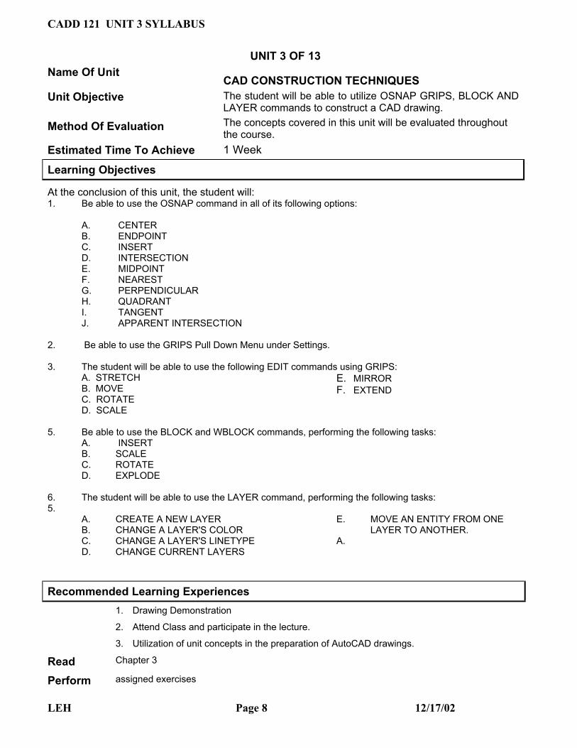
UNIT 3 OF 13 Name Of Unit
CAD CONSTRUCTION TECHNIQUES Unit Objective The student will be able to utilize OSNAP GRIPS, BLOCK AND
LAYER commands to construct a CAD drawing. Method Of Evaluation The concepts covered in this unit will be evaluated throughout
the course. Estimated Time To Achieve 1 Week
Learning Objectives
At the conclusion of this unit, the student will: 1. Be able to use the OSNAP command in all of its following options:
A. CENTER B. ENDPOINT C. INSERT D. INTERSECTION E. MIDPOINT F. NEAREST G. PERPENDICULAR H. QUADRANT I. TANGENT J. APPARENT INTERSECTION
2. Be able to use the GRIPS Pull Down Menu under Settings. 3. The student will be able to use the following EDIT commands using GRIPS: A. STRETCH B. MOVE C. ROTATE D. SCALE
E. MIRROR F. EXTEND
5. Be able to use the BLOCK and WBLOCK commands, performing the following tasks:
A. INSERT B. SCALE C. ROTATE D. EXPLODE
6. The student will be able to use the LAYER command, performing the following tasks: 5.
A. CREATE A NEW LAYER B. CHANGE A LAYER'S COLOR C. CHANGE A LAYER'S LINETYPE D. CHANGE CURRENT LAYERS
E. MOVE AN ENTITY FROM ONE LAYER TO ANOTHER.
A.
Recommended Learning Experiences
1. Drawing Demonstration
2. Attend Class and participate in the lecture.
3. Utilization of unit concepts in the preparation of AutoCAD drawings.
Read Chapter 3
Perform assigned exercises
LEH Page 8 12/17/02

CADD 121 UNIT 4 SYLLABUS
UNIT 4 OF 13 Name Of Unit
SKETCHING Unit Objective The student will be able to create two dimensional and three
dimensional freehand sketches. Method Of Evaluation The concepts covered in this unit will be evaluated throughout
the course. Estimated Time To Achieve 1 Week.
Learning Objectives
At the conclusion of this unit, the student will:
1. Know how to select graph paper and pencils to create the required sketches.
2. Know how to sketch lines
3. Know how to maintain proper proportions in sketches.
4. Know how to sketch curves.
5. Know how to create isometric sketches.
6. Know how to create oblique sketches.
7. Know how to create perspective sketches. Recommended Learning Experiences
1. Classroom Drawing Demonstration.
2. Construction of an orthographic drawing in AutoCAD.
3. Attend Class and participate in the lecture.
Read
Perform assigned exercises
LEH Page 9 12/17/02

CADD 121 UNIT 4 SYLLABUS
UNIT 5 OF 13 Name Of Unit
ORTHOGRAPHIC PROJECTION Unit Objective The student will be able to create an orthographic drawing with
AutoCAD. Method Of Evaluation The concepts covered in this unit will be evaluated throughout
the course. Estimated Time To Achieve 1 Week.
Learning Objectives
At the conclusion of this unit, the student will be able to: 1. The student will understand the theory of orthographic projection. 2. The student will be able to visualize an object in 3 views. 3. The student will know the precedence of lines, especially solid, hidden, and centerlines, and be
able to change linetypes in AutoCAD. 4. The student will be able to draw the following features in orthographic views using AutoCAD: A. Hidden Surfaces B. Slanted Surfaces C. Oblique Surfaces D. Compound Lines E. Rounded Surfaces F. Holes G. Cylinders H. Irregular Surfaces I. Castings
J. Thin-walled Objects Recommended Learning Experiences
1. Classroom Drawing Demonstration.
2. Construction of an orthographic drawing in AutoCAD.
3. Attend Class and participate in the lecture.
Read Chapter 5
Perform assigned exercises
LEH Page 10 12/17/02

CADD 121 UNIT 5 SYLLABUS
UNIT 6 OF 13 Name Of Unit
BASIC DIMENSIONING Unit Objective The student will be able to Dimension an AutoCAD Drawing.
Method Of Evaluation The concepts covered in this unit will be evaluated throughout the course.
Estimated Time To Achieve 1 Week.
Learning Objectives
At the conclusion of this unit, the student will: 1. Be able to define the following, and
explain its usage: A. Dimension Line B. Extension Line C. Leader D. General Dimension or Note E. Locate Dimension or Note F. Size Dimension G. Location Dimension
2. Be able to use Dimension styles to alter dimensions’ features.
3. Be able to create the following dimensions: A. ALIGNED B. RADIUS C. DIAMETER D. ANGULAR E. BASELINE F. CHAIN
4. Be able to create Center Marks... 5. Be able to edit existing dimension text. 6. Be able to dimension the following
configurations in AutoCAD: A. Holes B. Radii C. Fillets & Rounds D. Irregular Shapes E. Polar Dimensions
7. Be able to dimension or call out the following features: A. CHAMFERS B. KNURLS C. KEYS AND KEWAYS
10. The student will be able to utilize both Centerline and Coordinate Dimensioning.
Recommended Learning Experiences 1. Drawing Demonstration
2. Dimensioning of an AutoCAD drawing.
3. Utilization of chapter concepts in the preparation of AutoCAD drawings.
4. Attend Class and participate in the lecture.
Read Chapter 8
Perform assigned exercises
LEH Page 11 12/17/02

CADD 121 UNIT 6 SYLLABUS
UNIT 7 OF 13 Name Of Unit
SECTIONAL VIEWS Unit Objective The student will be able to construct a sectional drawing using
AutoCAD. Method Of Evaluation The concepts covered in this unit will be evaluated throughout
the course. Estimated Time To Achieve 1 Week.
Learning Objectives
At the conclusion of this unit: 1. The student will know that sectional drawings are used to expose internal surfaces. 2. The student will be able to create a Cutting Plane Line. 3. The student will be able to use the HATCH command to draw section lines in a specified area. 4. The student will be able to use HATCH Pull Down Menu to choose various styles of section lines. 5. The student will be able to draw the following types of sectional drawings with AutoCAD: A. Offset Sections B. Multiple Sections C. Aligned Sections D. Half Sections E. Partial Sections F. Broken-out Sections G. Removed Sections H. Sectional Breaks 6. The student will know how to treat webs ribs and spokes in section. Recommended Learning Experiences
1. Drawing Demonstration
2. Construction of a Sectional Drawing in AutoCAD.
3. Attend Class and participate in the lecture.
Read Chapter 6
Perform assigned exercises
LEH Page 12 12/17/02

CADD 121 UNIT 7 SYLLABUS
UNIT 8 OF 13 Name Of Unit
AUXILIARY VIEWS Unit Objective The student will be able to draw an Auxiliary Drawing using
AutoCAD. Method Of Evaluation The concepts covered in this unit will be evaluated throughout
the course. Estimated Time To Achieve 1 Week.
Learning Objectives
At the conclusion of this unit, the student will be able to: 1. The student will know that an auxiliary view is an orthographic view showing the true shape of a slant or oblique surface. 2. The student will be able to perform the following tasks to construct and auxiliary view: A. Projection between normal and auxiliary view. B. Transferring lines between views. C. Projecting rounded surfaces. D. Projecting irregular surfaces. 3. The student will be able to construct the following auxiliary views in AutoCAD: A. Partial Auxiliary Views B. Sectional Auxiliary Views C. Auxiliary Views of Oblique Surfaces
D. Secondary Auxiliary Views Recommended Learning Experiences
1. Classroom Drawing Demonstration.
2. Construction of an auxiliary drawing in AutoCAD.
3. Attend Class and participate in the lecture.
Read Chapter 7
Perform assigned exercises
LEH Page 13 12/17/02

CADD 121 UNIT 10 SYLLABUS
UNIT 9 OF 13 Name Of Unit
GEOMETRIC DIMENSIONING & TOLERANCING Unit Objective The student will be able to add tolerances to AutoCAD
dimensioned drawings. Method Of Evaluation The concepts covered in this unit will be evaluated throughout
the course. Estimated Time To Achieve 2 Weeks.
Learning Objectives
At the conclusion of this unit, the student will: 1. The student will be able to create the following tolerances using AutoCAD: A. Plus and Minus B. Limit Tolerance C. Angular Tolerance 2. The student will be able to create the following types of dimensions in AutoCAD: A. Chain Dimensioning B. Baseline Dimensioning C. Rectangular Dimensioning 3. The student will be able to recognize and use standard tolerances. 4. The student will be able to define and use
the following: A. Standard Fits B. Nominal Sizes C. Preferred and Standard Size D. Surface Finishes E. Surface Control Symbols
5. The student will be able to define the following Geometric Tolerances of Form: A. Flatness
B. Straightness (RFS and MMC) C. Cylindricity D. Circularity
6. The student will be able to apply geometric tolerancing using AutoCAD. 7. The student will be able to define the
following Geometric Tolerances of Orientation:
A. Datum B. Perpendicularity C. Parallelism D. Angularism E. Profiles F. Runouts 8. The student will be able to explain the following Positioning Tolerances:
A. Virtual Condition B. Floating Fasteners C. Fixed Fasteners
Recommended Learning Experiences
1. Drawing Demonstration
2. Tolerancing an AutoCAD drawing.
3. Utilization of unit concepts in the preparation of AutoCAD drawings.
4. Attend Class and participate in the lecture.
Read Chapters 9 and 10
Perform assigned exercises
LEH Page 14 12/17/02

CADD 121 UNIT 9 SYLLABUS
UNIT 10 OF 13 Name Of Unit
THREADS AND FASTERERS Unit Objective The student will be able to represent threads and fasteners on
AutoCAD drawings. Method Of Evaluation The concepts covered in this unit will be evaluated throughout
the course. Estimated Time To Achieve 1 Week.
Learning Objectives
At the conclusion of this unit, the student will: 1. The student will be able to define the following items of thread terminology: A. Pitch B. Major Diameter C. Minor Diameter D. Root E. Crest 2. Utilizing the standard items of thread specification, the student will be able to indicate the following: A. Thread Form B. Major Diameter C. Number of Threads per Inch D. Internal or External Thread 3. Using AutoCAD, the student will be able to draw the following thread representations:
A. Detailed B. Schematic C. Simplified 4. The student will be able to explain the usage of the following: A. Nuts & Bolts B. Screws C. Studs D. Washers E. Set Screws F. Keys G. Rivets H. Springs 5. The student will be able to use AutoCAD to draw the items in Objective 4.
Recommended Learning Experiences 1. Drawing Demonstration
2. Construction of a Drawing in AutoCAD.
3. Utilization of unit concepts in the preparation of AutoCAD drawings.
4. Attend Class and participate in the lecture.
Read Chapter 11
Perform assigned exercises
LEH Page 15 12/17/02

CADD 121 UNIT 11 SYLLABUS
UNIT 11 OF 13 Name Of Unit
WORKING DRAWINGS Unit Objective The student will be able to construct a set of working drawings
in AutoCAD. Method Of Evaluation The concepts covered in this unit will be evaluated throughout
the course. Estimated Time To Achieve 3 Weeks.
Learning Objectives
At the conclusion of this unit, the student will: 1. The student will be able to differentiate between detail and assembly drawings. 2. The student will be able to utilize the following components of a drawing format: A. Title Block B. Revision Block C. Tolerance Blocks D. Release Block E. Parts List/Bill of Materials 3. The student will be able to explain the usage of the following: A. Notes B. First Angle Projection Recommended Learning Experiences
1. Drawing Demonstration
2. Preparation of a set of working drawings in AutoCAD.
3. Attend Class and participate in the lecture.
Read Chapter 12
Perform assigned exercises
LEH Page 16 12/17/02

CADD 121 UNIT 12 SYLLABUS
UNIT 12 OF 13 Name Of Unit
GEARS, BEARINGS, AND CAMS Unit Objective The student will be able to draw Gears, Bearings, and/or Cams
in AutoCAD. Method Of Evaluation The concepts covered in this unit will be evaluated throughout
the course. Estimated Time To Achieve 1 Week.
Learning Objectives
At the conclusion of this unit, the student will: 1. The student will be able to explain the following terms of gear terminology: A. Pitch Diameter B. Diametral Pitch C. Circular Pitch D. Preferred Pitches E. Center Distance F. Backlash G. Addendum H. Dedendum
I. Whole Depth J. Working Depth K. Circular Thickness L. Face Width M. Outside Diameter N. Root Diameter O. Clearance P. Pressure Angle
2. The student will know how to draw the following gear types us AutoCAD. A. Spur Gears B. Bevel Gears C. Worm Gears D. Helical Gears E. Racks 3. The student will know how to draw the following items in AutoCAD: A. Ball Bearings B. Bushings 4. The student will know how to create cam displacement diagrams in AutoCAD for the following: A. Uniform Motion B. Harmonic Motion C. Uniform Acceleration and Deceleration Motion Recommended Learning Experiences
1. Drawing Demonstration
2. Attend Class and participate in the lecture.
Read Chapter 13
Perform assigned exercises
LEH Page 17 12/17/02

CADD 121 UNIT 12 SYLLABUS
UNIT 13 OF 13 Name Of Unit
FUNDAMENTALS OF 3D DRAWING Unit Objective The student will be able to construct pictorial drawings using
AutoCAD. Method Of Evaluation The concepts covered in this unit will be evaluated throughout
the course. Estimated Time To Achieve 3 Weeks.
Learning Objectives
At the conclusion of this unit, the student will: 1. The student will be able to utilize the Drawing Aids Pull Down Menu to set up the following:
A. Isometric Grid & Snap B. The Three Isoplanes C. TOP D. LEFT E. RIGHT
2. The student will be able to draw an Isometric Ellipse in all three isoplanes. 3. The student will be able to change the isoplane by using the keyboard toggle CONTROL E. 4. The student will be able to create and edit an Isometric Drawing in AutoCAD. 5. The student will be able to create, save and work with User Defined Coordinate Systems
(UCS’s). 6. The student will be able to create orthographic views from 3-D objects. Recommended Learning Experiences
1. Drawing Demonstration
2. Construction of an Isometric Drawing in AutoCAD.
3. Attend Class and participate in the lecture.
Read Chapter 14
Perform assigned exercises
LEH Page 18 12/17/02