Embed Size (px)
Citation preview

1
Learning legacyLessons learned from the London 2012 Games construction project
Reducing embodied carbon through efficient design
AuthorsJonathan M Cullen BEng MPhil PhDWellMet2050, University of Cambridge
Mark A Carruth MEng MA (Cantab)WellMet2050, University of Cambridge
Muiris Moynihan MEngWellMet2050, University of Cambridge
Julian M Allwood MEng MA (Cantab) MBa PhDWellMet2050, University of Cambridge
Dan Epstein BSc(Hons) MSc (Oxon)Olympic Delivery Authority
AbstractAs the operational carbon emissions from buildings are reduced through energy efficiency measures, the embodied carbon emissions in construction materials become more significant.
The need to consider embodied emissions in the construction of the Olympic Park was further accentuated by the short 30-day use-phase for the London 2012 Olympic and Paralympic Games and the less frequent use of the venue after the Games, which results in two-thirds of the total carbon emissions being released before the Games even begin.
Having said that, about 75 per cent of those emissions were embedded in developments which were designed for use after the Games.
While no specific embodied carbon targets were set during the planning stage, the drive to reduce costs and build efficient structures in the project brief and during the design process led to significant savings in embodied carbon. In this report, four case studies are selected – the Olympic Stadium, the Aquatics Centre, the Velodrome, and the Structures, Bridges and Highways – and embodied carbon emission savings, ranging from nine per cent to 38 per cent, are calculated.
A number of technical and logistical design lessons are drawn from the analysis before comparing the performance of the London 2012 venues with past Olympic Games’ venues. Finally, benchmarks for embodied carbon are set for different types of sporting venues, based on best practice results.
Embodied emissions was a key consideration in the construction of the Olympic Park

2
IntroductionIt is easy to make the connection between running a car, heating a building or turning on a television set, and the carbon emissions that result. What is not so obvious are the carbon emissions embodied in the construction materials – the steel and concrete used to make buildings and infrastructure. Yet concrete and steel alone account for 15 per cent of the global carbon emissions from energy and industrial processes, and about two-thirds of all concrete and steel is used in construction1.
The term ‘embodied carbon’ is used to describe the cumulative release of carbon emissions along the entire materials supply chain: from mining, through production and processing, to manufacture and finally, construction. This is different from the use-phase emissions, which are released during the operational lifetime of a building, and result from burning fossil fuels for heating and using electricity for powering devices.
Much attention has been focused on reducing operational emissions, with good results, whereas less effort has been directed towards reducing embodied emissions. In some new-build cases, the embodied carbon in construction materials now dominates the total lifecycle emissions of the project, leading to calls for designers to focus on embodied carbon as a key input to the design process.
For the Park, the need to consider embodied carbon was even more pronounced. The Olympic and Paralympic Games will be held over a short 30-day period leading to low use-phase carbon emissions. Having said that, about 75 per cent of those emissions are embedded in developments which have been designed for use after the Games when the Olympic site will be transformed by removing temporary bridges, structures, highways and/or downsizing all or parts of the venues.
The London 2012 reference carbon footprint study2 which covers the seven-year period from winning to staging the Games, but excludes legacy emissions in line with the Green House Gas protocol3,4, estimates that more than two-thirds of the total 3.4 MtCO2e carbon footprint will occur before the Games even start, mostly in the construction of venues and transport infrastructure, as shown in Figure 1.
The high proportion of emissions attributed to embodied carbon will come as a surprise to the design community who have only recently become aware of the importance of embodied carbon, especially in sporting venues.
Equally, if the issue had been better known, the Olympic Delivery Authority (ODA) might have set specific embodied carbon targets for venues and infrastructure in their Sustainable Development Strategy5, and further reduced embodied carbon emissions, rather than relying solely on good design and engineering to deliver results.
Figure 2 shows that for the specific venues analysed in this study, concrete, reinforcing steel and structural steel each contribute around 30 per cent of the embodied carbon in materials, with the remaining 10 per cent consisting of materials such as aggregates, blockwork, glass, insulation, timber, aluminium and plastics. Setting effective targets for the three main materials alone would have impacted more than 90 per cent of the embodied carbon in these structures.
Two key strategies were used at the Park to reduce the embodied carbon of venues and infrastructure. The first was to use low carbon concrete mixes and the second was to design structures with less materials.
% 8
13% Operations
50% Venues
%20% Spectators
17% Transport Infrastructure32% Structural steel
30% Concrete30% Reinforcing steel
8% Other
26.9
50
20
13
30
30
17
32
Figure 1: London 2012 carbon footprint by activity
% 8
13% Operations
50% Venues
%20% Spectators
17% Transport Infrastructure32% Structural steel
30% Concrete30% Reinforcing steel
8% Other
26.9
50
20
13
30
30
17
32
Figure 2: Breakdown of embodied carbon in construction materials

3
Two separate research papers published by Best Foot Forward6 and Kirsten Henson7 show that a 35–38 per cent reduction in the carbon emissions from concrete was achieved across the Park. These savings resulted from several strategies including: – raising the average percentage
of cement substitutions (PFA and GGBS) to 32 per cent from the UK average of 18 per cent;
– using superplasticisers to reduce total cementitious content in the concrete;
– selecting a single energy efficient concrete supplier that achieved a five per cent reduction in carbon footprint against the UK average; and
– locating the ready mix concrete plant on site adjacent to the rail head, which eliminated 60,000 heavy vehicle movements.
This study acknowledges the importance of cement substitution in reducing embodied carbon emissions, but does not include these savings. Instead, it focuses only on the savings from the second, and potentially more important, strategy: using efficient design to reduce the quantity of construction materials required (note: on-site energy use and transport emissions also contributed to embodied carbon for construction, but were outside the scope of this study).
This approach is most effective when targets are set early in the concept and design processes, and included in the design brief. Embodied carbon has been reduced at the 2012 Games by designing out redundant elements, lightweighting, value engineering (cost-reduction) and detailed optimisation.
The ODA focused early on providing long-term benefits from the London 2012 Games, ensuring that the legacy venues were not oversized by making use of temporary elements in the Olympic Stadium, Aquatics Centre, concourse, bridges and structures. In addition, the application of good design, value engineering and innovative solutions at the Park have resulted in embodied carbon savings.
This study examines four cases studies – the Olympic Stadium, the Aquatics Centre, the Velodrome, and the Structures, Bridges and Highways (SBH) – to explore how design efficiency was incorporated into the Park’s venues and infrastructure.
Workers engaged in a concrete pour on the L03 Bridge, Olympic Park, February 2010
60,000Heavy vehicle movements eliminated by locating the concrete plant on site.
4
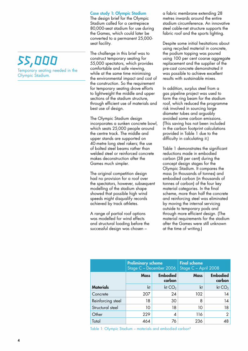
Case study 1: Olympic StadiumThe design brief for the Olympic Stadium called for a centrepiece 80,000-seat stadium for use during the Games, which could later be converted to a permanent 25,000-seat facility.
The challenge in this brief was to construct temporary seating for 55,000 spectators, which provides comfortable and safe viewing, while at the same time minimising the environmental impact and cost of the construction. So the requirement for temporary seating drove efforts to lightweight the middle and upper sections of the stadium structure, through efficient use of materials and best use of design.
The Olympic Stadium design incorporates a sunken concrete bowl, which seats 25,000 people around the centre track. The middle and upper stands are supported on 40-metre long steel rakers; the use of bolted steel beams rather than welded steel or reinforced concrete makes deconstruction after the Games much simpler.
The original competition design had no provision for a roof over the spectators, however, subsequent modelling of the stadium shape showed that possible high wind speeds might disqualify records achieved by track athletes.
A range of partial roof options was modelled for wind effects and structural loading before the successful design was chosen –
a fabric membrane extending 28 metres inwards around the entire stadium circumference. An innovative steel cable-net structure supports the fabric roof and the sports lighting.
Despite some initial hesitations about using recycled material in concrete, the podium topping was poured using 100 per cent coarse aggregate replacement and the supplier of the pre-cast concrete demonstrated it was possible to achieve excellent results with sustainable mixes.
In addition, surplus steel from a gas pipeline project was used to form the ring beam for the stadium roof, which reduced the programme risk involved in sourcing large diameter tubes and arguably avoided some carbon emissions. (This saving has not been included in the carbon footprint calculations provided in Table 1 due to the difficulty in calculating it.)
Table 1 demonstrates the significant reductions made in embodied carbon (38 per cent) during the concept design stages for the Olympic Stadium. It compares the mass (in thousands of tonnes) and embodied carbon (in thousands of tonnes of carbon) of the four key material categories. In the final scheme, more than half the concrete and reinforcing steel was eliminated by moving the internal servicing outside to temporary pods and through more efficient design. (The material requirements for the stadium after the Games were still unknown at the time of writing.)
Preliminary scheme Stage C – December 2006
Final scheme Stage C – April 2008
Mass Embodied carbon
Mass Embodied carbon
Materials kt kt CO2 kt kt CO2
Concrete 207 24 102 14
Reinforcing steel 18 30 8 14
Structural steel 10 18 10 18
Other 229 4 116 2
Total 464 76 236 48
Table 1: Olympic Stadium – materials and embodied carbon8
55,000Temporary seating needed in the Olympic Stadium.

5
Case study 2: Aquatics Centre The Aquatics Centre was awarded to a signature architect to be an ‘iconic’ building for the London 2012 Games. The key element of the design was ‘an undulating roof that sweeps up from the ground as a wave’. This was initially manifested as two long-spanning curves, but was soon rationalised to one by locating the training pool beneath the main bridge into the Park.
The remaining 120-metre span over the competition pools had to accommodate the insertion of temporary stands as well as allowing uninterrupted views for spectators. To achieve this, the Design team proposed a steel arch solution with a post-tensioned tie through the substructure, with the arches inclined to put the laterally spanning secondary trusses in tension, and so reduce their weight.
This system required the roof and substructure to be completed in tandem which carried programme risk, therefore a heavier-weight steel truss roof solution was pursued, which was not as reliant on the rest of the building’s construction timeline (the early completion of the roof also provided shelter for the concrete and other ongoing works). This solution also required the extensive use of scaffolding during construction of the roof and later the installation of the ceiling.
This structure was highly optimised during design – realising a 95 per cent utilisation factor (ratio of actual to maximum permitted stress) and detailed analysis of realistic ‘ponding’ and ice formation on the roof allowed a more reduced imposed load than standard code requirements. Though strength governed, the deflections needed to be accurately understood so that the wooden cladding on the underside of the roof remained inline, to help the backstroking swimmers stay on course.
After the Games, the two large temporary stands on either side will be removed, reducing the capacity by 15,000 seats. These stands were designed specifically with removal in mind, so that each beam is a standard catalogue section and the connections are all bolted and standardised; this inherently prevents highly optimised material use but future re-use was considered the more important design criterion.
Initial plans to use scaffolding technology for the stands were dropped because the parabolic stands (for sightlines) would not be bought back by the supplier. As this decision was made after the foundations were cast, the redesign had to accommodate the sub-optimal placements, reducing the design efficiency.
The Aquatics Centre was awarded to a signature architect to be an ‘iconic’ building for the London 2012 Games
Programme risk was the driver for a heavier-weight steel truss roof solution on the Aquatics Centre.

6
The Aquatics Centre took the lead on testing concrete mixes with varying levels of aggregate and cement replacement, and then shared the results with the other projects to overcome reservations about performance and surface finish. In the final design, foundations were poured with 76 per cent recycled aggregate, and one-third of the superstructure (with its complex forms) used 55–70 per cent cement replacement. Even for visible concrete surfaces, requiring a higher level of surface finish, 40 per cent cement replacement was still achieved.
The following design trade-offs and constraints prevented further efficiency gains: – choosing a more structurally
efficient, but still iconic, roof shape in the early design stages could have given substantial material and carbon savings;
– less programme pressure could have allowed the lighter-weight arch design to proceed instead of the heavier truss solution;
– if the temporary stands had not been changed after the foundations were poured, a more efficient structure could have been built;
– the requirement to deconstruct the temporary stands, leading to specification of standard sections and connections, limited their optimisation, but did allow for future re-use.
Despite these constraints, Table 2 still shows that a 10 per cent reduction in embodied carbon was achieved during the detailed design of the Aquatics Centre, between stages C and E, which apply to the Games. The savings after the Games are 27 per cent.
Stage C scheme Stage E scheme Legacy scheme
Mass Embodied carbon
Mass Embodied carbon
Mass Embodied carbon
Materials kt kt CO2 kt kt CO2 kt kt CO2
Concrete 102 11 108 11 108 11
Reinforcing steel 9 15 7 12 7 12
Structural steel 8 14 7 12 3 5
Other 6 2 6 2 6 2
Total 125 42 128 37 128 30
Table 2: Aquatics Centre – materials and embodied carbon9
The Aquatics Centre took the lead on testing concrete mixes with varying levels of aggregate and cement replacement.

7
Case study 3: VelodromeThe Design team’s vision for the Velodrome called for a minimal structure, ‘shrink-wrapped’ around the track and spectators. The resulting roof geometry could be constructed with a cable-net structure spanning the 130-metre track area, but an overly cautious cost estimate and the client’s concerns about the risk led to the cable-net being abandoned in favour of a more conventional steel arch system.
However, the contractor commissioned to build the structure and their consultants could see significant cost and programme savings in resurrecting the cable-net scheme and persuaded the client to commission a study into four alternative roof systems, including: a tensioned cable-net, compressive steel arches, glulam timber arches and a cable and timber hybrid system.
The cable-net option was then reselected and resulted in a 15 per cent saving in embodied carbon over the original competition scheme, and a 27 per cent saving over the steel arch option, as shown in Table 3.
Two specific design solutions led to additional material savings. Firstly, the roof ring beam and the bowl for the stands and track were combined into a single system, which required additional analysis to predict the performance of the structure, but led to significant material savings.
Secondly, the lightweight seating structure performed outside the historic dynamic code limits, but more rigorous dynamic analysis (based on a pre-publication version of a new method) was undertaken to ensure the structure would behave adequately – the standard solution would have doubled the required weight of structural steel.
The following design trade-offs and constraints prevented further efficiency gains: the roof could have been made lighter still if a fabric covering was used instead of the chosen aluminium finish, which was a design life, maintenance and aesthetic constraint; the Velodrome is a permanent venue with indoor temperature control necessitating insulation in the roof, which added weight; a more optimal bowl geometry could have improved efficiency, however, this would have constrained track layout.
Competition scheme 2007
Flat scheme Early 2008
Steel arch scheme Mid 2008
Construction scheme Early 2009
Mass Embodied carbon
Mass Embodied carbon
Mass Embodied carbon
Mass Embodied carbon
Materials kt kt CO2 kt kt CO2 kt kt CO2 kt kt CO2
Concrete 20.0 2.3 28.5 3.3 25.9 3.0 16.6 1.9
Reinforcing steel 1.5 2.6 2.5 4.4 2.4 4.1 1.7 2.9
Structural steel 1.4 2.5 0.9 1.6 1.0 1.7 0.8 1.5
Other 4.8 1.3 4.2 1.1 4.6 1.2 4.2 1.1
Total 27.6 8.7 36.2 10.4 33.9 10.1 23.3 7.4
Images
Table 3: Four alternative roof options for the Velodrome10
15%Embodied carbon saving resulted from selecting a cable-net roof option for the velodrome.

8
Case study 4: Structures, bridges and highwaysSignificant reductions in embodied carbon were made on a number of projects and elements between the initial and construction designs for the SBH. Table 4 shows a cross-section of selected infrastructure projects where a carbon saving of 25 per cent was achieved through lightweight structures and temporary solutions, following more accurate modelling and testing to remove uncertainty.
Pile structures were required to deal with variable ground conditions at the Park and initial designs called for 2,700 Vibro-Concrete Column (VCC) piles, and 173 Continuous Flight Augur (CFA) piles between seven bridges. A saving of 24 per cent in carbon emissions was achieved by: – reducing the number of VCC piles
to 2,000 after on-site testing removed uncertainty and allowed design refinement;
– shortening the CFA piles by 10 per cent after refining the geotechnical parameters; and
– increasing the use of cement replacement in the concrete mix to 40 per cent.
The bridges around the Park underwent an optimisation study that reduced both their number and their size, with the knock-on effect of reducing the carbon emissions by 26 per cent from the original design. Some bridges were eliminated and others downsized following more accurate modelling of crowd flows. Careful analysis of the post-Games requirements permitted temporary bridge sections to be designed with shorter life expectancies and so less material.
The ‘Loop Road’ Highway was redesigned to incorporate more of the existing highways on the site, reducing material requirements for concrete, reinforcing steel and asphalt.
Temporary (‘Games-only’) portions of road were identified and subject to a thinner design and temporary pavements were made leaner for a design life of only four years.
These measures reduced the embodied carbon of the highways by nine per cent. Code requirements prevented recycled aggregates being used in permanent highways and bridges, limiting the scope for further savings.
Structures Highways Bridges SBH
Concept Construction Concept Construction Concept Construction Concept Construction
Materials kt CO2 kt CO2 kt CO2 kt CO2 kt CO2 kt CO2 kt CO2 kt CO2
Concrete 1.6 1.1 20 15 22 16
Reinforcing steel
1.0 0.9 17 15 18 16
Structural steel 22 14 22 14
Other 5.1 4.7 2 1 7 6
Total 2.6 2.0 5.1 4.7 61 45 69 52
Table 4: Embodied carbon in structures, highways and bridges 11
Careful analysis of the post-Games requirements permitted temporary bridge sections to be designed.

9
Analysis and discussionAlthough no specific embodied carbon targets for materials were set for the Park, large relative savings were achieved by reducing quantities of construction materials, through a combination of efficient design, elimination and value engineering.
This section provides a review of the technical and logistical approaches used by the architects, engineers and contractors to achieve these emissions savings. However, to judge the success of these efforts requires a comparison of embodied carbon across several Olympic venues, both past and present.
How do the London 2012 venues compare to each other, and to the venues of previous Olympics? What wider lessons have been learned about including embodied carbon in design targets? What embodied carbon benchmarks can be targeted for future venues?
Review of the technical approachesSeveral lessons can be learned by analysing the approaches used to reduce carbon emissions in the design of the Park venues and infrastructure. In some cases the approach was planned and intentional; in others the approach emerged as a co-benefit of good engineering design or cost savings. Three key lessons were identified:
Set a clear brief for legacy – a key objective for the ODA was to balance the required seating capacity for the Games with the long-term legacy requirements for the venue. History has shown that many Olympic venues are oversized for the legacy phase, and therefore the investment is underutilised after the Games.
Legacy considerations led to several different solutions: for some venues the Games and legacy specifications could be matched, resulting in a permanent venue (Velodrome and Handball Arena); for other venues, downsizing after the Games is necessary to meet the legacy needs, involving the removal of temporary seating stands (Olympic Stadium and Aquatics Centre), using lightweight temporary pods structures on the island site for hospitality services to allow easy removal following the Games; several permanent bridges were replaced by lighter temporary bridges after considering the long-term infrastructure requirements; other bridges had temporary portions that will be removed to make them narrower after the Games; for other venues the entire construction is
temporary and will be deconstructed after the Games (Basketball Arena, Hockey Centre and Water Polo).
This flexible approach to matching the Games and legacy requirements will ensure the venues are utilised fully, and is needed to justify the significant financial, material and embodied carbon investment in the Park. It is important to note that every city hosting an international event like the Olympics has its own legacy needs, and comparing approaches across different Olympics is therefore not necessarily always a fair comparison.
Integrate functional requirements – a holistic design will allow multiple design requirements to be met by a single solution, so reducing the overall material requirements. For example, integrating the structural frame of a building with its thermal envelope (inner and outer skins) reduces the material required (as compared with separate systems) by combining these functions.
Four specific examples of integrated design from London 2012 are highlighted here. Firstly, the F10 land bridge, which provides land access from Stratford City Centre to the Park, also forms part of the Aquatics Centre roof, providing significant cost and environmental benefit.
Secondly, the Velodrome roof support structure also carries the load of the seating stands and the exterior cladding. As these three functions were met by a single structural system, the amount of structural steel needed was reduced.
Large relative savings have been achieved through a combination of efficient design, elimination and value engineering.

10
Thirdly, by considering the access requirements for the Park during construction, Games and legacy phases together, an integrated road access solution was found that works for all three scenarios in a materially efficient manner.
Fourthly, the main stadium is designed with the lower 25,000 seats built below the site ground level for a more efficient design.
Avoid over-specification – significant material and embodied carbon savings were made at the Park by optimising the structural designs of the venues and infrastructure. This work typically occurred in the concept phase, by questioning what is the best solution, and in the detailed design phase, by matching specific loads with lean structural solutions. In some cases reducing the material demand required additional testing of the construction materials, to have confidence in the outcome.
For example, testing the strength and surface finishes of a range of low carbon concrete mixes was necessary to meet the 25 per cent average recycled aggregate target for the Games, and a site-specific concrete supply chain was created, with the support of the ODA, to supply these sustainable mixes and give added quality and risk control for the contractors.
In other cases additional modelling and monitoring was performed to prove that designs ‘outside the code’ still behaved within accepted limits.
For example, the natural frequency of the Velodrome stand structure is approximately 2.3 Hertz, well below the value of 3.5Hz recommended by the building codes. Detailed computer modelling and post-construction vibration tests were used to confirm that crowd dynamics would not be a problem in the finished buildings.
The technical lessons described above were, for some venues, complemented by the targeting of low embodied carbon early in the design process.
Early injection of carbon targets in the design processAt every stage of design there is scope for improved material efficiency – many of the London 2012 construction projects saw major embodied carbon savings made in the detailed design stages. However, the earlier carbon emissions are prioritised, the greater the impact.
Projects that write low carbon targets for materials into the design brief, encourage collaboration between the architect, engineer and contractor to explore and review efficient design options, and carry out detailed optimisation work during technical design, will invariably be lower in embodied carbon.
The Design team’s vision for the Velodrome called for a minimal structure, ‘shrink wrapped’ around the track and spectators
Computer modelling and post-construction vibration tests were used to confirm crowd dynamics rather than relying on recommendation of the code.
11
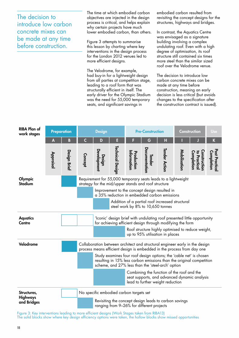
The time at which embodied carbon objectives are injected in the design process is critical, and helps explain why certain projects have much lower embodied carbon, than others.
Figure 3 attempts to summarise this lesson by charting where key interventions in the design process for the London 2012 venues led to more efficient designs.
The Velodrome, for example, had buy-in for a lightweight design from all parties at competition stage, leading to a roof form that was structurally efficient in itself. The early driver for the Olympic Stadium was the need for 55,000 temporary seats, and significant savings in
embodied carbon resulted from revisiting the concept designs for the structures, highways and bridges.
In contrast, the Aquatics Centre was envisaged as a signature building involving a complex undulating roof. Even with a high degree of optimisation, its roof structure still contained six times more steel than the similar sized roof over the Velodrome venue.
The decision to introduce low carbon concrete mixes can be made at any time before construction, meaning an early decision is less critical (but avoids changes to the specification after the construction contract is issued).
RIBA Plan of work stages Preparation Design Pre-Construction Construction Use
A B C D E F G H I J K
Olympic Stadium
Requirement for 55,000 temporary seats leads to a lightweight strategy for the mid/upper stands and roof structure
Improvement to the concept design resulted in a 35% reduction in embedded carbon emissions
Addition of a partial roof increased structural steel work by 8% to 10,650 tonnes
Aquatics Centre
‘Iconic’ design brief with undulating roof presented little opportunity for achieving efficient design through modifying the form
Roof structure highly optimised to reduce weight, up to 95% utilisation in places
Velodrome Collaboration between architect and structural engineer early in the design process means efficient design is embedded in the process from day one
Study examines four roof design options; the ‘cable net’ is chosen resulting in 15% less carbon emissions than the original competition scheme, and 27% less than the ‘steel-arch’ option
Combining the function of the roof and the seat supports, and advanced dynamic analysis lead to further weight reduction
Structures, Highways and Bridges
No specific embodied carbon targets set
Revisiting the concept design leads to carbon savings ranging from 9–26% for different projects
Appraisal
Design Brief
Concept
Design
Developm
ent
Technical Design
Production Inform
ation
Tender D
ocumentation
Tender Action
Mobilisation
Construction to Practical Com
pletion
Post Practical Com
pletion
Figure 3: Key interventions leading to more efficient designs (Work Stages taken from RIBA13) The solid blocks show where key design efficiency options were taken, the hollow blocks show missed opportunities
The decision to introduce low carbon concrete mixes can be made at any time before construction.

12
Comparison of embodied carbon across Olympic venuesLarge sporting venues are constructed differently for different purposes, in various sizes, for dissimilar environments, under varying lifetime assumptions and in distinct styles. Making a meaningful comparison of the embodied carbon in construction materials across such diverse structures is challenging.
For this study, the carbon embodied in materials was compared relative to three metrics – roof area, floor area and number of seats – with the three London 2012 venues being examined alongside the Sydney 2000 and Beijing 2008 Olympic stadiums. The results are shown in Figure 4 and key information about each project is given in Table 5 (please be aware that figures are approximate only).
Embodied carbon figures were calculated by multiplying the mass of each construction material (for example, tonnes of concrete) by the specific embodied carbon values taken from the Bath Inventory of Carbon and Energy (ICE) database12
(tonnes of carbon for each tonne of material). Note that these figures were used to benchmark the buildings – actual carbon figures for materials in China and Australia will differ – and transport and on-site construction activity was excluded from the analysis.
Construction materials were grouped into four categories – concrete, reinforcing steel, structural steel and other – representing the largest contributors to embodied carbon (see the supporting information for details). The embodied carbon for each venue was divided by floor area, roof area and number of seats, to give comparable metrics. Further details can be found in the supporting information, including assumptions.
Figure 4: Embodied carbon comparison for venues
Olympic Stadium London 2012
Aquatics Centre London 2012
Velodrome London 2012
National Stadium Beijing 2008
Stadium Australia Sydney 2000
Embo
died
car
bon
(t C
O2
/ m
etric
)
10
8
6
4
2
0
per roof area
per floor area
per seat
Making a meaningful comparison of the embodied carbon in construction materials across such diverse structures is challenging.

13
Table 5: Key stadium information including materials and embodied carbon8,9,10
Olympic Stadium London 2012
Aquatics Centre London 2012
Velodrome London 2012
National Stadium Beijing 2008
Stadium Australia Sydney 2000
General Games Legacy
Capacity 80,000 seats 17,500 seats
2,500 seats
6,000 seats 91,000 seats 110,000 seats
Floor area 110,000m2 43,000m2 29,000m2 21,000m2 258,000m2 160,000m2
Roof area 24,500m2 17,000m2 11,000m2 13,200m2 40,000m2 30,000m2
Architect Populous Zaha Hadid Architects Hopkins Herzog & de Meuron
Populous
Engineer Buro Happold Arup Expedition Engineering
Arup Sinclair Knight Merz
Start/completion May 2008– 2011
2007–2011 2009–2011 December 2003 – June 2008
September 1996 – March 1999
Temporary/permanent?
Permanent (downsized to 25,000 seats)
Permanent (downsized to 2,500 seats)
Permanent Permanent (downsized to 80,000 seats)
Permanent (downsized to 83,500 seats)
Heated/cooled? No Yes Yes No No
Roof coverage Partial Complete Complete Partial Partial
Materials
Concrete (kt) 102 108 108 17 1,300 210
Reinforcing steel (kt)
8 7 7 2 62 10
Structural steel (kt)
10 7 3 1 38 12
Embodied CO2
Total CO2 (kt) 48 37 30 7.4 370 72
CO2/roof area (t/m2)
1.9 2.2 2.8 0.56 9.3 2.4
CO2/seat (t/seat)
0.60 2.1 12.1 1.2 4.1 0.65
CO2/floor area (t/m2)
0.44 0.87 1.1 0.35 1.5 0.45
Images

14
The three London 2012 venues serve very different design aims, giving rise to variable values for embodied carbon. The Velodrome performed best on the per floor area and per roof area metrics, reflecting the early priority to create a simple lightweight structure in the design process.
In contrast, the higher embodied carbon for the Aquatics Centre resulted from choosing an iconic and more complex design, which was integral to winning the bid for the London 2012 Games. This demonstrates the importance of including embodied carbon targets early in the design process, but also raises the question: what constitutes an ‘iconic’ design?
When seating capacity is considered the Olympic Stadium excelled, because once the sporting arena was established, the marginal carbon cost of adding more seats diminished. The Olympic Stadium, at a capacity of 80,000, has the most seats of the three venues and thus the best carbon per seat value, although the number of seats after the Games will reduce.
The Aquatics Centre and the Velodrome both have fully covered arenas with internal temperature control, whereas the seating for the Olympic Stadium is only partially covered and open to the environment.
Furthermore, both the Olympic Stadium and the Aquatics Centre have temporary seating and support structures that will be deconstructed at the end of the Games. Taking only legacy capacity into account for the Aquatics Centre gave a very different result which is shown in Table 5. No figures have been given for the legacy London 2012 Olympic Stadium because agreed changes have not been finalised at the time of writing.
Comparing the absolute embodied carbon of the main stadia, the construction of the Sydney Stadium (used for the Sydney 2000 Games) created 1.5 times more carbon emissions than the London 2012 Olympic Stadium, while the Beijing 2008 Olympic Stadium (known as the ‘bird’s nest’) was nearly eight times more carbon intensive.
Accounting for seating capacities shows the London and Sydney stadia to be almost equal (0.60 compared to 0.65 tonne of carbon per seat), however, the Beijing design still dwarfs the others at 4.1 tonne of carbon per seat.
It would appear that although there is the capability to design and construct low carbon venues, it is not always matched by a desire to do so – when no attempt is made to control embodied carbon a truly ‘heavyweight’ solution results.
The Aquatics Centre was unveiled exactly one year before the start of the London 2012 Games
The higher embodied carbon for the Aquatics Centre results from choosing an iconic and more complex design.

15
Setting benchmarks for future Olympic venuesToday’s designers of Olympic venues are still drawn to pursuing iconic designs for their creations, specifying difficult to construct forms and using material quantities well in excess of the pure structural requirements. This is perhaps the most significant barrier to achieving low embodied carbon designs. Yet, designers could choose to create both iconic and structurally efficient designs, and indeed in the future might even be required to do so. What embodied carbon benchmarks should they target?
Table 6 presents targets for stadium venues (partially covered, but open to the air) and fully enclosed venues based on a conservative improvement to the best value found in the analysis. Such benchmarks should be included as design targets in the client brief alongside a clear statement of the desire to reduce embodied carbon emissions, to ensure the selection of a suitable Design team and thus secure the delivery of a low carbon venue.
Table 6: Suggested embodied carbon benchmarks for venues
Venue Type Benchmark Range Target Unit
Stadium venues Embodied carbon per seat 0.60–4.10 0.55 t CO2/seat
Embodied carbon per floor area 0.45–1.50 0.40 t CO2/m2
Fully enclosed venues Embodied carbon per roof area 0.56–2.20 0.50 t CO2/m2
Embodied carbon per floor area 0.35–0.87 0.30 t CO2/m2
ConclusionDesigners are beginning to understand the importance of the carbon emissions generated from construction activities, where efficient and cost effective designs lead to lower embodied carbon.
Four case studies from the London 2012 Games – Olympic Stadium, Aquatics Centre, Velodrome, and Structures, Buildings and Highways – were analysed to quantify the reductions in embodied carbon achieved. However, when the Olympic venues were compared to each other, and with the Beijing and Sydney Olympic stadia, large differences in the absolute carbon emissions were found. The analysis shows that low carbon designs result when efficient design principles are included early in the concept and design phases.
Benchmarks for embodied carbon are set to encourage efficient designs with low embodied carbon, and the inclusion of these benchmarks in the bidding process for future Olympic venues is recommended. Iconic designs need not be ‘carbon heavy’, with the London 2012 designs for the Velodrome and the Olympic Stadium providing a refreshing contrast to this rule.
Low carbon designs result when efficient design principles are included early in the concept and design phases.

16
References1 Allwood, J.M., Cullen, J.M. and Milford, R.L. (2008). Options for
achieving a 50% cut in industrial carbon emissions by 2050, Environmental Science and Technology, 44(6):1888–1894.
2 London 2012 (2010). Carbon footprint study: methodology and reference footprint. Available from: www.london2012.com/publications/carbon-footprint-study.php (accessed 31 August 2011).
3 WBCSD and WRI (2004). The greenhouse gas protocol: a corporate accounting and reporting standard. Revised edition. Available from: www.ghgprotocol.org/standards/corporate-standard (accessed 31 August 2011).
4 BSI (2008). PAS2050: Assessing the life cycle greenhouse gas emissions of goods and services. Available from: bsi-global.com/en/Standards-and-Publications/How-we-can-help-you/Professional-Standards-Service/PAS-2050/ (accessed 31 August 2011).
5 Olympic Delivery Authority (2007). Sustainable development strategy. Available from: www.london2012.com/documents/oda-publications/oda-sustainable-development-strategy-executive-summary.pdf (accessed 31 August 2011).
6 Simmons, C (2009). The carbon footprint of the concrete used by London 2012. Best Foot Forward.
7 Henson K. (2010). Procurement and use of sustainable concrete on the Olympic Park. Draft paper, London 2012.
8 Buro Happold (2009). Comparison of several stadiums. Internal document.
9 Arup (2009). Aquatics footprint carbon saving. Internal document.
10 Expedition Engineering and Hopkins Architects (2010). London 2012 Olympic Velopark: embodied carbon study.
11 Burgess C. and Ko J. (2010). Study of carbon footprint reduction during design of Olympic Park infrastructure. Olympic Delivery Authority (ODA) and Arup, UK.
12 Hammond, G. and Jones C. (2008) Inventory of carbon and energy (ICE), Department of Mechanical Engineering, University of Bath, UK
13 RIBA (2008). Outline plan of work 2007, Amended in 2008, Royal Institute of British Architects, UK.
AcknowledgementsMany thanks to the project teams for Velodrome, Aquatics Centre, Olympic Stadium and Structures, Bridges and Highways for providing the data for this report. Thanks also to those within the ODA and the ODA’s Delivery Partner for facilitating the production of the research. Finally, thank you to Jo Carris, Kirsten Henson, Judith Sykes and Chris Wise for their input.
Peer reviewers – Craig Simmonds (Best Foot Forward) – Cecilia Bagenholm (Burro Happold) – Andrew Weir (Expedition)

17
© 2011 Olympic Delivery Authority. The official Emblems of the London 2012 Games are © London Organising Committee of the Olympic Games and Paralympic Games Limited (LOCOG) 2007. All rights reserved.
The construction of the venues and infrastructure of the London 2012 Games is funded by the National Lottery through the Olympic Lottery Distributor, the Department for Culture, Media and Sport, the Mayor of London and the London Development Agency.
For more information visit: london2012.com/learninglegacy Published December 2011 ODA 2011/031