Embed Size (px)
Citation preview

Topic 4.4.1 – Simple AM Receiver
1
Learning Objectives: At the end of this topic you will be able to; draw a block diagram, and circuit diagram for a simple radio receiver,
consisting of antenna, tuned circuit, detector/demodulator, and
earphones;
describe the function of each of these sub-systems;
appreciate that a tuned circuit is a variable frequency band pass filter;
design a tuned circuit to select a particular carrier frequency;
select and use the equation Lf
Co224
1π
= to calculate the value of C to
provide a given resonant frequency.
use the frequency response curves of a loaded tuned circuit to explain
poor selectivity.
Module ET4 – Communication Systems
2
The Simple Radio Receiver
In section 4.3 we discussed a range of methods for linking an information signal with a high frequency carrier by means of a number of modulation techniques so that it can be transmitted. In this section we will explore some ways of retrieving the original signal so that it can be heard.
We will start with the simple radio receiver, which consists of five main functional blocks as shown below:
Every radio receiver requires an antenna (aerial) as the input, to convert the incoming radio waves into tiny alternating currents. Unlike the transmitting aerial which may only be transmitting one frequency from the radio station, the aerial will pick up all of the different radio broadcasts at different carrier frequencies within range. The actual current variation in the aerial will be a complex mixture of all these signals and so the first thing the receiver has to be designed to do is select one broadcast from among the many, and then extract its audio information. The tuning circuit A tuning circuit is essentially a band pass filter (Topic 4.2.3) designed to pick up carrier frequencies typically in the range 300kHz to 3MHz. The frequency range (i.e. the frequency band it passes) can be altered by means of a variable capacitor. The frequency response of the tuning circuit is the gain as a function of frequency, where
ageinput volttageoutput volgain =
This is shown opposite (a) is the block diagram, (b) is the frequency response.
Antenna Tuned Circuit
Detector
RF Filter High Impedance Headphones
Topic 4.4.1 – Simple AM Receiver
3
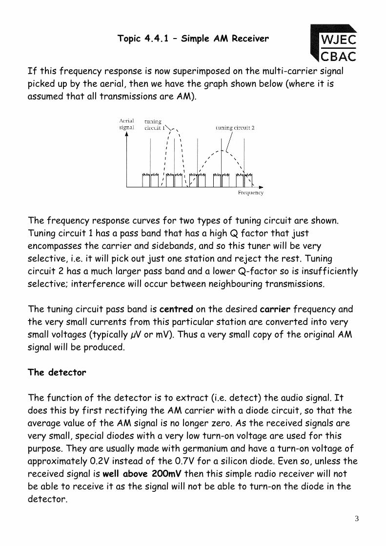
If this frequency response is now superimposed on the multi-carrier signal picked up by the aerial, then we have the graph shown below (where it is assumed that all transmissions are AM).
The frequency response curves for two types of tuning circuit are shown. Tuning circuit 1 has a pass band that has a high Q factor that just encompasses the carrier and sidebands, and so this tuner will be very selective, i.e. it will pick out just one station and reject the rest. Tuning circuit 2 has a much larger pass band and a lower Q-factor so is insufficiently selective; interference will occur between neighbouring transmissions. The tuning circuit pass band is centred on the desired carrier frequency and the very small currents from this particular station are converted into very small voltages (typically µV or mV). Thus a very small copy of the original AM signal will be produced. The detector The function of the detector is to extract (i.e. detect) the audio signal. It does this by first rectifying the AM carrier with a diode circuit, so that the average value of the AM signal is no longer zero. As the received signals are very small, special diodes with a very low turn-on voltage are used for this purpose. They are usually made with germanium and have a turn-on voltage of approximately 0.2V instead of the 0.7V for a silicon diode. Even so, unless the received signal is well above 200mV then this simple radio receiver will not be able to receive it as the signal will not be able to turn-on the diode in the detector.

Module ET4 – Communication Systems
4
The RF filter
The half wave rectified pulses are then smoothed with a low pass filter, so that the remaining carrier frequency is lost and the slowly changing envelope (i.e. the audio signal) is obtained as output. The process of detection and filtering is shown below.
Note: a different type of low pass filter is used in the final stage as the type
used in Topic 4.2.2. have a series resistor which would reduce the very small current in the radio receiver to an unacceptably low value. The good news however is that you don’t have to know how this filter works just that it’s break frequency is given by the same formula i.e.
RCfb π2
1= .
This output would be obtained before the filter is connected.
This output would be obtained if the filter is connected.

Topic 4.4.1 – Simple AM Receiver
5
In practice the received signal would never be perfectly reproduced, the following diagrams show a more realistic output from the RF filter.
This is the amplitude modulated carrier. This is the half wave rectified signal
The red line shows the attempt of the filter to reconstruct the original audio wave. The values of R and C used affect the quality of how smooth the peaks are joined. The recovered audio frequency which is not perfectly smooth, and contains fluctuations.
The values of R and C need to be chosen carefully to produce:
• a break frequency just above the audio range of the information signal • a time constant that is short compared with the period of the audio
signal so the output follows the audio signal faithfully • a time constant that is long compared with the period of the carrier so
that C does not discharge appreciably and give a saw tooth effect superimposed on the audio signal
• a high impedance so that it does not draw a large current from the tuned circuit

Module ET4 – Communication Systems
6
As a rule of thumb compromise, R is usually chosen to be greater than 50 kΩ along with a corresponding value of C in the range 20 to 1000pF. The High Impedance Headphones
This is a transducer that converts the audio signal into small displacements of a diaphragm, so that the original audio information is recreated. The minor fluctuations in the audio signal tend to be ignored by most headphones. As this radio receives all of its power from the received radio signal it is unable to drive any output device other than very high impedance (~1MΩ) headphones . Circuit diagram The circuit diagram for a simple radio receiver is shown below.
Note : Sometimes the resistor in the RF filter is omitted from the circuit diagram because the internal impedance of the headphones is sufficient to work with the fixed capacitor to form the low pass filter. This circuit is powered only by the signal picked up by the antenna, no batteries or power supplies are needed. If you wanted to replace the headphones with a loudspeaker you would have to add an audio amplifier which would need a power source after the RF Filter.
Antenna Tuned Circuit
Detector
RF filter
High Impedance Headphones

Topic 4.4.1 – Simple AM Receiver
7
There are only a couple of calculations that can be performed on this circuit, which are as follows:
i. using the tuned circuit components to calculate the range of frequencies that can be received by the radio, or given the frequency of a radio station, calculate the setting of the variable capacitor to ensure that this frequency is the one received.
ii. Calculating suitable values for the RF filter circuit, so that it has a high impedance to the audio signal, and low impedance to the RF carrier.
We will now look at a couple of examples to see how these various calculations are performed. However it is important to remember that all calculations will be based on a theoretical model, where loading effects will be ignored. 1. The following circuit shows a simple radio receiver (a) Calculate the minimum and maximum frequency that the tuned
circuit of this radio can respond to. (b) (i) Calculate the break frequency of the RF Filter. (ii) Comment on the suitability of the break frequency for this
particular radio receiver.
10mH 20pF-60pF 100pF 100kΩ1

Module ET4 – Communication Systems
8
Solution: (a) To calculate the resonant frequency of the tuned circuit for
minimum and maximum values of the variable capacitor we must apply the formula o
12
fLCπ
= twice for the two extremes of
capacitance value. The minimum frequency will be obtained when C is at its maximum
value i.e. 60pF, so
(min) 3 12
(min) 13
12
12 10 10 60 10
1 205468 Hz 205 kHz2 6 10
o
o
o
fLC
f
f
π
π
π
− −
−
=
=× × ×
= = ≈×
The maximum frequency will be obtained when C is at its minimum
value i.e. 20pF, so
(max) 3 12
(max) 13
12
12 10 10 20 10
1 355881 Hz 356 kHz2 2 10
o
o
o
fLC
f
f
π
π
π
− −
−
=
=× × ×
= = ≈×
The tuning range of this tuned circuit is therefore 205 kHz –
356 kHz (b) i. The break frequency of the RF filter is given by the following
formula RC
fb π21
=
3 12
12 100 10 100 1015915.49 Hz16 kHz
bf π −=× × × ×
=≈

Topic 4.4.1 – Simple AM Receiver
9
ii. The audio frequency range broadcast on an AM transmission is limited to approximately 5 kHz. The break frequency is higher than the highest audio frequency so any audio signal that is broadcast will pass through the RF filter.
In addition the break frequency is much lower than any RF
frequency that can be picked up by the receiver. The RF filter is therefore suitable for this radio receiver.
Note for the Enthusiast
1. The break frequency of the filter is 16 kHz 2. The time constant of the filter is 10 µs 3. The period of the audio signal is 200 µs at 5 kHz 4. The period of the carrier is a maximum of 5 µs 5. The impedance of the filter is approximately 90 kΩ
The values of R and C chosen hold up quite well when compared to the requirements stated earlier. The only exception is that the filter time constant is not long compared with the period of the carrier so a slight saw tooth effect would be superimposed on the audio signal. The problem occurs in this case due to the relatively low carrier frequency

Module ET4 – Communication Systems
10
2. The following diagram shows an incomplete simple radio receiver. (a) Complete the circuit diagram for a simple radio receiver,
(component values are not required). (b) The simple radio receiver is tuned to receive a radio station
broadcasting on a carrier frequency of 1170 kHz. (i) Calculate the value of impedance of the inductor at 1170 kHz. (ii) State the value of impedance of the capacitor at 1170 kHz. (iii) Calculate the value of C set on the variable capacitor to
receive the radio station transmitting at 1170 kHz. (c) The user would like to re-tune the radio to receive a radio station
transmitting on a carrier frequency of 450 kHz. Show by calculation if this is possible.
Solution (a)
2.2mH 1pF-50pF
2.2mH 1pF-50pF

Topic 4.4.1 – Simple AM Receiver
11
(b) (i) The impedance of the inductor at resonance is given by the formula LfX oL π2= , where the resonant frequency = 1170 kHz.
3 3
2
2 1170 10 2.2 1016172.91 16173
L oX f Lπ
π −
=
= × × × × ×= Ω≈ Ω
(ii) At resonance, the impedance of the capacitor will be the same as the impedance of the inductor, therefore XC = 16173Ω
(iii) Either using the or re-arranging the formula for XC resonance formula. (c) Either : calculate the lowest or calculate the value of frequency the circuit C required to receive can receive. the required station.
o
3 12
12
12 2.2 10 50 10479870Hz480 kHz
fLCπ
π − −
=
=× × ×
=≈
2 2o
2 3 2 3
11
14
14 (450 10 ) 2.2 105.685 10 F57 pF
Cf Lπ
π −
−
=
=× × × ×
= ×≈
Either method shows that the station transmitting on 450 kHz
cannot be received. The lowest frequency that can be received is 480 kHz, and the second method shows that C would have to be set at 57 pF to make the resonant frequency 450 kHz.
3
12
12
12
12 1170 10 161738.41 10 F8.41 pF
Co
o C
Xf C
Cf X
π
π
π−
=
=
=× × ×
= ×=
( )
2 2
2 3 3
12
14
14 1170 10 2.2 10
8.41 10 F8.41 pF
o
Cf Lπ
π −
−
=
=× × × × ×
= ×=

Module ET4 – Communication Systems
12
3. The following diagram shows an incomplete radio receiver. (a) Complete the circuit diagram for the simple radio receiver.
(Component values are not required) (b) The radio receiver must receive radio signals broadcast over the
frequency range 350 kHz – 1350 kHz (i) Calculate the break frequency of the RF Filter. (ii) Comment on the suitability of the break frequency for this
particular radio receiver. Solution: (a)
470pF 150kΩ
470pF 150kΩ

Topic 4.4.1 – Simple AM Receiver
13
(b) i. The break frequency of the RF filter is given by the following formula
RCfb π2
1=
3 12
12 150 10 470 102257.5 Hz2.3 kHz
bf π −=× × × ×
=≈
ii. The audio frequency range broadcast on an AM transmission
is limited to approximately 5 kHz. The break frequency is much lower than the highest audio frequency transmitted, therefore frequencies above 2.3 kHz will be attenuated. The RF filter is therefore un-suitable for this radio receiver.
Issues with the Simple Radio Receiver.
The simple radio receiver has two major problems. 1. It is not very sensitive – radio stations have to be very strong, to
generate a large enough voltage in the antenna (aerial) to switch on the germanium diode. That is it cannot pick up weak stations.
2. It is not very selective – using a single tuned circuit it is difficult
to obtain a high Q-factor which makes it difficult for the radio to select a single station without picking up a signal from any neighbouring stations and thus causing interference where two overlapping sounds can be heard.
We will look at ways of improving these two flaws in our next topic – 4.2.2 Advanced Radio Receivers Now here are a few questions for you to try.

Module ET4 – Communication Systems
14
Student Exercise 1 1. The following circuit shows a simple radio receiver (a) Calculate the minimum and maximum frequency that the tuned
circuit of this radio can respond to. ..............................................................................................................................
..............................................................................................................................
..............................................................................................................................
..............................................................................................................................
..............................................................................................................................
..............................................................................................................................
..............................................................................................................................
..............................................................................................................................
(b) (i) Calculate the break frequency of the RF Filter. ..............................................................................................................................
..............................................................................................................................
..............................................................................................................................
3mH 100pF-500pF 220pF 240kΩ

Topic 4.4.1 – Simple AM Receiver
15
(ii) Comment on the suitability of the break frequency for this particular radio receiver.
..............................................................................................................................
..............................................................................................................................
..............................................................................................................................
..............................................................................................................................
..............................................................................................................................
2. The following diagram shows an incomplete simple radio receiver. (a) Complete the circuit diagram for a simple radio receiver,
(component values are not required). (b) The simple radio receiver is tuned to receive a radio station
broadcasting on a carrier frequency of 680 kHz. (i) Calculate the value of impedance of the inductor at 680 kHz.
..............................................................................................................................
..............................................................................................................................
3.3mH 15pF-100pF

Module ET4 – Communication Systems
16
(ii) State the value of impedance of the capacitor at 680 kHz.
..............................................................................................................................
(iii) Calculate the value of C set on the variable capacitor to receive the radio station transmitting at 680 kHz.
..............................................................................................................................
..............................................................................................................................
..............................................................................................................................
..............................................................................................................................
..............................................................................................................................
(c) The user would like to re-tune the radio to receive a radio station transmitting on a carrier frequency of 350 kHz. Show by calculation if this is possible.
..............................................................................................................................
..............................................................................................................................
..............................................................................................................................
..............................................................................................................................
..............................................................................................................................
..............................................................................................................................

Topic 4.4.1 – Simple AM Receiver
17
3. The following diagram shows an incomplete radio receiver. (a) Complete the circuit diagram for the simple radio receiver.
(Component values are not required) (b) The radio receiver must receive radio signals broadcast over the
frequency range 500 kHz – 1600 kHz (i) Calculate the break frequency of the RF Filter. ...................................................................................................................
...................................................................................................................
...................................................................................................................
(ii) Comment on the suitability of the break frequency for this particular radio receiver.
...................................................................................................................
...................................................................................................................
...................................................................................................................
...................................................................................................................
...................................................................................................................
...................................................................................................................
330pF 36kΩ

Module ET4 – Communication Systems
18
Solutions to Student Exercise: 1. (a) The minimum frequency will be obtained when C is at its maximum
value i.e. 500 pF, so
(min) 3 12
(min) 13
12
12 3 10 500 10
1 129949 Hz 130 kHz2 6 10
o
o
o
fLC
f
f
π
π
π
− −
−
=
=× × ×
= = ≈×
The maximum frequency will be obtained when C is at its minimum
value i.e. 100pF, so
(max) 3 12
(max) 13
12
12 3 10 100 10
1 290575 Hz 291 kHz2 2 10
o
o
o
fLC
f
f
π
π
π
− −
−
=
=× × ×
= = ≈×
The tuning range of this tuned circuit is therefore 130 kHz –
291 kHz (b) i. The break frequency of the RF filter is given by the following
formula RC
fb π21
=
3 12
12 240 10 250 102652.58 Hz2.7 kHz
bf π −=× × × ×
=≈
ii. The audio frequency range broadcast on an AM transmission
is limited to approximately 5 kHz. The break frequency is within the broadcast range and the RF filter is therefore un-suitable for this radio receiver.

Topic 4.4.1 – Simple AM Receiver
19
2. (a) (b) (i)
Ω≈Ω=
×××××=
=−
141004714099
10331068022
33
..π
π LfX oL
(ii) At resonance, the impedance of the capacitor will be the same as the impedance of the inductor, therefore XC = 14100 Ω
(iii) Either
3
11
12
12
12 680 10 141001.659 10 F16.59 pF
Co
o C
Xf C
Cf X
π
π
π−
=
=
=× × × ×
= ×=
3.3mH 15pF-100pF

Module ET4 – Communication Systems
20
or
( )
2 2
22 3 3
11
14
1
4 680 10 3.3 10
1.660 10 F16.60 pF
o
Cf Lπ
π −
−
=
=× × × × ×
= ×=
(c) Either :
3 12
12
12 3.3 10 100 10277053.19 Hz277 kHz
of LCπ
π − −
=
=× × × × ×
=≈
Or
( )
2 2
22 3 3
11
14
1
4 350 10 3.3 10
6.265 10 F63 pF
o
Cf Lπ
π −
−
=
=× × × × ×
= ×≈
Either method shows that the receiver can receive a frequency of
350 kHz.

Topic 4.4.1 – Simple AM Receiver
21
3. (a)
(b) i. The break frequency of the RF filter is given by the following formula
RCfb π2
1=
3 12
12 36 10 330 1013396.88 Hz13 kHz
bf π −=× × × ×
=≈
(ii) The audio frequency range broadcast on an AM transmission
is limited to approximately 5 kHz. The break frequency is higher than the highest audio frequency so any audio signal that is broadcast will pass through the RF filter.
In addition the break frequency is much lower than any RF
frequency that can be picked up by the receiver. The RF filter is therefore suitable for this radio receiver. Now for some examination style questions.
330pF 36kΩ

Module ET4 – Communication Systems
22
Examination Style Questions 1. The following shows the circuit diagram for a simple radio receiver.
a) Calculate the lowest frequency to which the receiver can respond. ................................................................................................................................................. ................................................................................................................................................. ................................................................................................................................................. ................................................................................................................................................. ................................................................................................................................................. .................................................................................................................................................
[3] b) Describe and explain the part played by the following components in this receiver. i) The diode ................................................................................................................................................. ................................................................................................................................................. .................................................................................................................................................
[2] ii) The fixed capacitor ................................................................................................................................................. ................................................................................................................................................. .................................................................................................................................................
[2]

Topic 4.4.1 – Simple AM Receiver
23
2. A simple radio receiver consists of the following sub-systems:
detector antenna headphones RF filter tuned circuit (a) Draw the block diagram for this receiver.
[1]
(b) (i) Name the component used as the detector, which modifies the RF signal to give a non-zero average audio signal voltage.
......................................................................
[1] (ii) Name the component used as a demodulator, which separates the audio signal from
the RF carrier. ......................................................................
[1]
(c) Here is part of the circuit diagram for the tuned circuit.
(i) Complete the diagram by adding the second component needed to allow the user to
select different radio stations. [1]

Module ET4 – Communication Systems
24
(ii) Choose a suitable range of values for this second component to allow the receiver to tune to radio broadcasts in the frequency range 500 kHz to 1000 kHz.
You must give the correct unit with your answer. ................................................................................................................................................. ................................................................................................................................................. ................................................................................................................................................. .................................................................................................................................................
[3] (iii) The receiver is tuned to an AM radio station broadcasting on a carrier frequency of
800 kHz. The radio station broadcasts a signal ranging in frequency from 40Hz to 4 kHz. What is the lowest frequency the tuned circuit must respond to, in order to receive this signal?
................................................................................................................................................. .................................................................................................................................................
[1] (iv) Sketch a graph to show how the inductive reactance of the inductor changes with
frequency. [2]
(v) At the resonant frequency of the tuned circuit, what is significant about the reactance of the inductor and the reactance of the capacitor ?
................................................................................................................................................. .................................................................................................................................................
[1]

Topic 4.4.1 – Simple AM Receiver
25
3. Here is the circuit diagram for a simple radio receiver.
(a) What is the name of the sub-system made up of components B and C? .................................................................................................................................................
[1] (b) Component E is a 20nF capacitor. (i) Calculate its reactance at a frequency of 200 kHz. Give the correct unit for your
answer. ................................................................................................................................................. ................................................................................................................................................. ................................................................................................................................................. .................................................................................................................................................
[2] (ii) Estimate its reactance at audio frequencies. ..................................................................................
[1] (iii) Hence explain how the system demodulates the AM signal. ................................................................................................................................................. ................................................................................................................................................. ................................................................................................................................................. ................................................................................................................................................. ................................................................................................................................................. .................................................................................................................................................
[3]

Module ET4 – Communication Systems
26
4. Here is a block diagram of a simple radio receiver.
a. The circuit diagram of the Tuned circuit is shown below.
i) Radio Wales transmits on a carrier frequency of 882 kHz. Calculate the reactance
of the inductor at 882 kHz. Give the unit. [2]
...................................................................................................................................... ...................................................................................................................................... ...................................................................................................................................... ii) What should the reactance of the variable capacitor be if the circuit is to pick up
Radio Wales. [1]
...................................................................................................................................... iii) Calculate the value of the variable capacitor when receiving Radio Wales.
[2]
...................................................................................................................................... ...................................................................................................................................... ...................................................................................................................................... b. Name the component used as the detector in the simple radio receiver.
[1] .................................................................................................................................................
AerialTunedCircuit Detector RF Filter
Headphones
-
2pF - 200pF1mH
Topic 4.4.1 – Simple AM Receiver
27
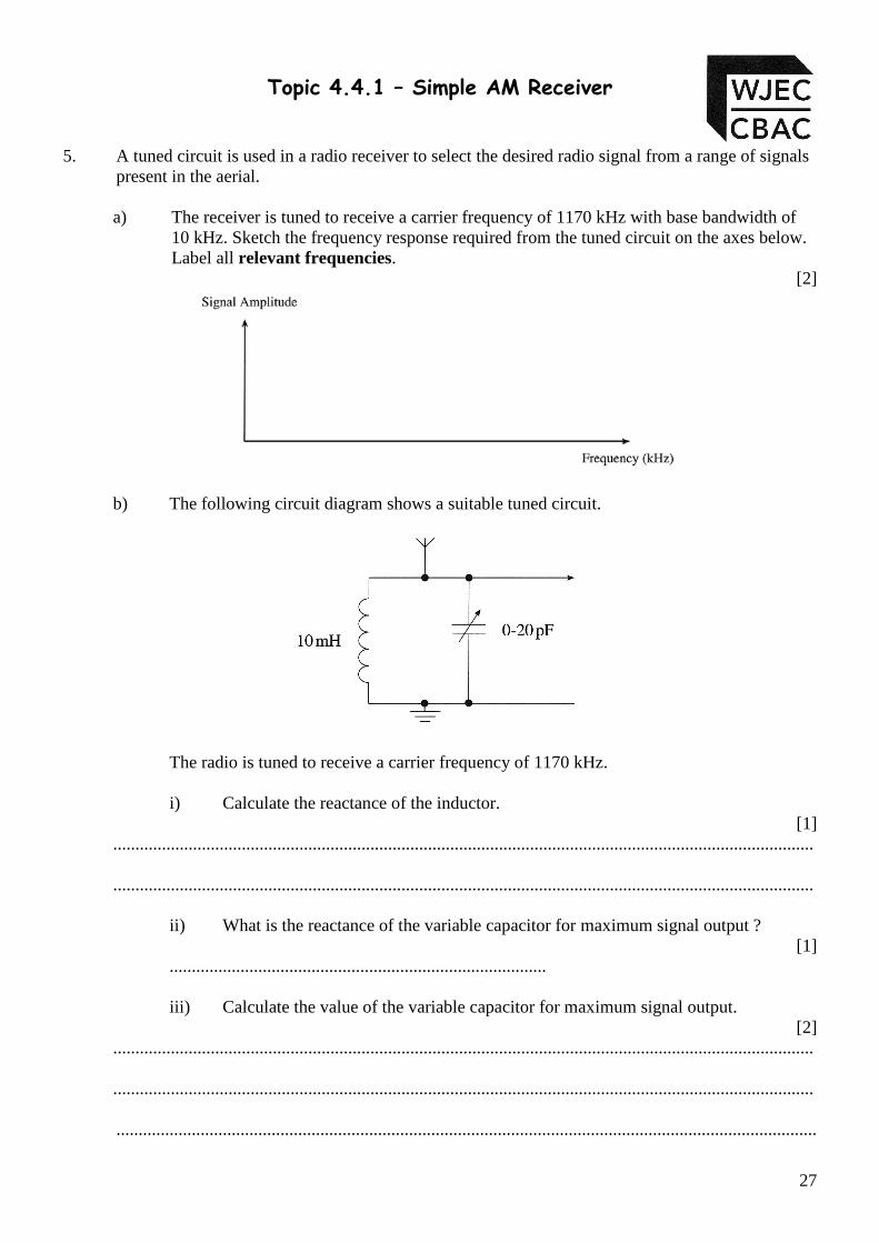
5. A tuned circuit is used in a radio receiver to select the desired radio signal from a range of signals present in the aerial.
a) The receiver is tuned to receive a carrier frequency of 1170 kHz with base bandwidth of
10 kHz. Sketch the frequency response required from the tuned circuit on the axes below. Label all relevant frequencies.
[2]
b) The following circuit diagram shows a suitable tuned circuit.
The radio is tuned to receive a carrier frequency of 1170 kHz. i) Calculate the reactance of the inductor.
[1] .............................................................................................................................................................. ..............................................................................................................................................................
ii) What is the reactance of the variable capacitor for maximum signal output ?
[1] ..................................................................................... iii) Calculate the value of the variable capacitor for maximum signal output.
[2] .............................................................................................................................................................. .............................................................................................................................................................. ..............................................................................................................................................................

Module ET4 – Communication Systems
28
6. The circuit diagram for a simple radio receiver is shown below.
a. Use the letters A - E to answer the following questions. i) Which component(s) modifies the RF signal to give a non-zero average audio signal. .......... ii) Which component(s) select the required RF signal .......... iii) Which component carries more than one RF signal ..........
[4] b. Calculate the highest frequency to which the above receiver can respond. ........................................................................................................................................................ ......................................................................................................................................................... ......................................................................................................................................................... .........................................................................................................................................................
[3] c. The earphones and 10nF capacitor form the low pass filter for the radio. The impedance of
the earphone is 1.2MΩ. i. Calculate the break frequency of the filter. ………………………………………………………………………………………. ……………………………………………………………………………………….
[2] ii. State with reasons whether this RF filter is effective in this case. ……………………………………………………………………………………….
……………………………………………………………………………………….
……………………………………………………………………………………….
[2]

Topic 4.4.1 – Simple AM Receiver
29
7. The simple radio receiver is made from five functional blocks. Two of the blocks are shown below.
RF Filter Detector
a) In the space below draw a block diagram to show how these blocks are connected together
to make a crystal radio receiver. [4]
b) What component is used in the detector block ? [1]
......................................................................................................................... c) What component is used in the RF Filter block ?
[1] .........................................................................................................................

Module ET4 – Communication Systems
30
d) Two possible tuned circuits for the radio are shown below.
Which circuit provides the user of the radio with the ability to select a frequency range
between 120 kHz and 250 kHz. You must show all of the calculations you have performed.
[3] .................................................................................................................................... .................................................................................................................................... .................................................................................................................................... .................................................................................................................................... .................................................................................................................................... .................................................................................................................................... .................................................................................................................................... .................................................................................................................................... .................................................................................................................................... .................................................................................................................................... .................................................................................................................................... .................................................................................................................................... .................................................................................................................................... .................................................................................................................................... .................................................................................................................................... ....................................................................................................................................
10-100pF 20-100pF10mH 20mHA B
Topic 4.4.1 – Simple AM Receiver
31
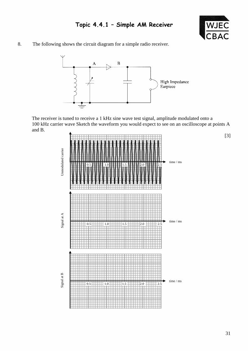
8. The following shows the circuit diagram for a simple radio receiver.
The receiver is tuned to receive a 1 kHz sine wave test signal, amplitude modulated onto a
100 kHz carrier wave Sketch the waveform you would expect to see on an oscilloscope at points A and B.
[3]
0.5 1.0 1.5 2.0 2.5 time / ms
Unm
odul
ated
car
rier
0.5 1.0 1.5 2.0 2.5 time / ms
Sign
al a
t A
0.5 1.0 1.5 2.0 2.5 time / ms
Sign
al a
t B

Module ET4 – Communication Systems
32
9. The following shows the circuit diagram for a simple radio receiver.
a. Explain the purpose of the following components in this receiver. i) The inductor and variable capacitor. .................................................................................................................................................. ..................................................................................................................................................
..................................................................................................................................................
[1] ii) The diode.
.................................................................................................................................................. ..................................................................................................................................................
..................................................................................................................................................
[1] iii) The fixed capacitor.
.................................................................................................................................................. ..................................................................................................................................................
..................................................................................................................................................
[1] b. Calculate the highest carrier frequency that the receiver can select. Give the unit. .................................................................................................................................................. ..................................................................................................................................................
.................................................................................................................................................. ..................................................................................................................................................
[3]

Topic 4.4.1 – Simple AM Receiver
33
10. A simple radio receiver is made from the following sub-systems.
Detector Tuned Circuit Headphones RF Filter
a. i) Complete the block diagram of the simple radio receiver, using the subsystems above.
[1]
ii) Name the component used as the detector in the simple radio receiver.
.................................................................................................................................................
[1] b. The circuit diagram of the tuned circuit is shown below.
i) Valleys Radio transmits on a carrier frequency of 999 kHz. Calculate the reactance of the inductor at 999 kHz. Give the unit.
[3] ...................................................................................................................................... ...................................................................................................................................... ......................................................................................................................................
Aerial

Module ET4 – Communication Systems
34
ii) State the reactance of the variable capacitor when the circuit is tuned to pick up Valleys Radio.
[1] ...................................................................................................................................... iii) Calculate the value of the variable capacitor when receiving Valleys Radio.
[2] ...................................................................................................................................... ...................................................................................................................................... ...................................................................................................................................... c. The simple radio receiver suffers from poor selectivity and sensitivity. What is meant by
poor sensitivity ? [1]
............................................................................................................................................................
............................................................................................................................................................
............................................................................................................................................................

Topic 4.4.1 – Simple AM Receiver
35
11. Here is a block diagram of a simple radio receiver.
a. Name the component used as the detector in the simple radio receiver.
[1] ................................................................................................................................................... b. The circuit diagram of the Tuned circuit is shown below.
i) Radio Five Live transmits on a carrier frequency of 693 kHz. Calculate the reactance of the inductor at 693 kHz. Give the unit.
[2] ....................................................................................................................................... ....................................................................................................................................... ....................................................................................................................................... ii) What is the reactance of the variable capacitor at 693 kHz?
[1] ....................................................................................................................................... iii) Calculate the value of the variable capacitor when tuned to receive Radio Five
Live, at 693 kHz. [2]
....................................................................................................................................... ....................................................................................................................................... .......................................................................................................................................
AerialTunedCircuit Detector RF Filter
Headphones
-

Module ET4 – Communication Systems
36
iv) Radio Five Live also broadcasts on 909 kHz. Show by calculation whether this tuned circuit can be adjusted to receive Radio Five Live at 909 kHz.
[2] ....................................................................................................................................... ....................................................................................................................................... ....................................................................................................................................... ....................................................................................................................................... c. The simple radio receiver suffers from poor selectivity and poor sensitivity. What is meant
by the terms poor selectivity and poor sensitivity?
Poor selectivity means .............................................................................................................. ................................................................................................................................................... ................................................................................................................................................... Poor sensitivity means .............................................................................................................. ................................................................................................................................................... ...................................................................................................................................................
[2]

Topic 4.4.1 – Simple AM Receiver
37
12. The following circuit shows a simple radio receiver (a) Calculate the minimum and maximum frequency that the tuned circuit of this radio can
respond to. ..................................................................................................................................................
..................................................................................................................................................
..................................................................................................................................................
..................................................................................................................................................
..................................................................................................................................................
..................................................................................................................................................
..................................................................................................................................................
..................................................................................................................................................
[3] (b) (i) Calculate the break frequency of the RF Filter. ..................................................................................................................................................
..................................................................................................................................................
[2]
(ii) Comment on the suitability of the break frequency for this particular radio receiver. ..................................................................................................................................................
..................................................................................................................................................
..................................................................................................................................................
..................................................................................................................................................
..................................................................................................................................................
[2]
0.1mH 200pF-800pF 100pF 82kΩ
Module ET4 – Communication Systems
38
(c) The user would like to re-tune the radio to receive a radio station transmitting on a carrier frequency of 475 kHz. Show by calculation if this is possible.
..................................................................................................................................................
..................................................................................................................................................
..................................................................................................................................................
..................................................................................................................................................
..................................................................................................................................................
..................................................................................................................................................
..................................................................................................................................................
..................................................................................................................................................
..................................................................................................................................................
..................................................................................................................................................
..................................................................................................................................................
..................................................................................................................................................
[3]

Topic 4.4.1 – Simple AM Receiver
39
13. The following diagram shows an incomplete simple radio receiver. (a) Complete the circuit diagram for a simple radio receiver, (component values are not
required). (b) The simple radio receiver is tuned to receive a radio station broadcasting on a carrier
frequency of 2340 kHz. (i) Calculate the value of impedance of the inductor at 2340 kHz.
..................................................................................................................................................
..................................................................................................................................................
..................................................................................................................................................
[2]
(ii) State the value of impedance of the capacitor at 2340 kHz.
..................................................................................................................................................
[1] (iii) Calculate the value of C set on the variable capacitor to receive the radio station
transmitting at 2340 kHz.
..................................................................................................................................................
..................................................................................................................................................
..................................................................................................................................................
..................................................................................................................................................
..................................................................................................................................................
0.22mH 10pF-470pF

Module ET4 – Communication Systems
40
14. The following diagram shows an incomplete radio receiver. (a) Complete the circuit diagram for the simple radio receiver. (Component values are not
required) (b) The radio receiver must receive radio signals broadcast over the frequency range
500 kHz – 1200kHz (i) Calculate the break frequency of the RF Filter. ..................................................................................................................................................
..................................................................................................................................................
..................................................................................................................................................
..................................................................................................................................................
[2]
(ii) Comment on the suitability of the break frequency for this particular radio receiver. ..................................................................................................................................................
..................................................................................................................................................
..................................................................................................................................................
..................................................................................................................................................
..................................................................................................................................................
..................................................................................................................................................
..................................................................................................................................................
..................................................................................................................................................
..................................................................................................................................................
[2]
820pF 120kΩ

Topic 4.4.1 – Simple AM Receiver
41
Self Evaluation Review
Learning Objectives My personal review of these objectives:
draw a block diagram, and circuit diagram for a simple radio receiver, consisting of antenna, tuned circuit, detector/demodulator, and earphones;
describe the function of each of these sub-systems;
appreciate that a tuned circuit is a variable frequency band pass filter;
design a tuned circuit to select a particular carrier frequency;
select and use the equation
LfC
o224
1π
= to calculate the value of C
to provide a given resonant frequency.
use the frequency response curves of a loaded tuned circuit to explain poor selectivity.
Targets: 1. ……………………………………………………………………………………………………………… ………………………………………………………………………………………………………………
2. ………………………………………………………………………………………………………………
………………………………………………………………………………………………………………