Embed Size (px)
Citation preview

Leading Technology for Next
Generation of LNG Carriers
Hoseong Lee, Ph.D.American Bureau of Shipping
Inha UniversitySeptember 25, 2006

Overview
• LNG Ship Capacity and Trends
• Leading LNG Technology
• Class Role

Deliveries Needed*22 21 35 21 20 17 18 20 22 24 25
Current Orderbook*
22 21 35 21
177 177 176 175 174 172 170 168 166 164 161
11 13 16
4273 88 107 122 138 156 176 198 220
1 752 3 922
2005 2006 2007 2008 2009 2010 2011 2012 2013 2014 2015
LNG Ship Supply-Demand ForecastLNG Ship Supply-Demand Forecast
Source: Current Fleet & Orderbook Clarkson **35-year-in-service basis
199219
250265
284299
315333
353375
397
Existing
NewDemand
ReplacedVessels**
In Number of Vessels – Jan. 2005
*
LNG Outlook
preliminary

LNG Trades & Potential Offshore Terminal Locations

Evolution of LNG Carrier Size300,000 m3
200,000 m3
100,000 m3
0
Cubic Meters
1964 1965 1969 1973 1975 1981 1995 2005 2009-2010
27,40025,500
71,500
87,600
120,000 125,000 133,000 135,000
153,000
250,000
IndependentPrismaticAluminumCargo Tanks
IndependentCylindricalTanks
First MossRosenbergIndependentSpherical Tanks
Ben Franklin& El Paso Kayser
FinimaFirst MembraneShips
2007
210/215
LNG Transport System TechnologyNext Generation of LNG Ships Require Advanced Technology that Addresses the Transport System
Propulsion Technology
Structural Integrity Technology
Pump Tower Analysis
Containment System Technology
Ship to Terminal Interface Technology
Technical ConsiderationsHull Structural Integrity
Structural Fatigue Strength
Terminal Compatibility
Propulsion Systems
Strength of Containment System
Vibration Performance
Pump Tower and Base Support
Larger LNG CarriersLarger LNG Carriers

FULL VESSEL 3D FEM ANALYSIS FULL VESSEL 3D FEM ANALYSIS for 40 Years Fatigue lifefor 40 Years Fatigue life
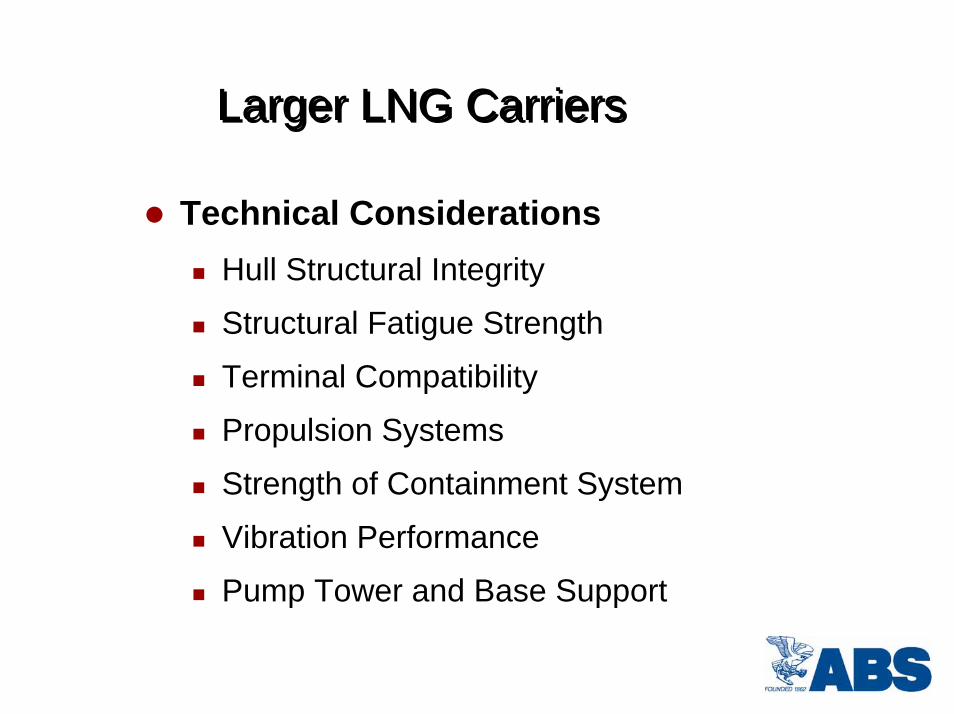
Containment System Strength
• Spot Market Trading of LNG• Arbitray Filling Condition
– Sloshing Impact for Membrane System
– Strength of Insulation System– Pump Tower Analysis– Ship Motion Coupling

Strength Assessment Procedure
Fig. 3 Strength Assessment Procedure for LNG Containment System
Technical Issues
• Gas Trapping and Cushioning Effect during Sloshing Impact
• Compressibility of Liquefied Gas
• Liquid-Structure Interaction (Hydroelasticity)
• Structural Damping of the Insulation System (Viscoelasticity)
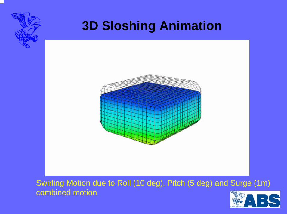
3D Sloshing Animation
Swirling Motion due to Roll (10 deg), Pitch (5 deg) and Surge (1m) combined motion

Sloshing Model Test at Marintek

Sloshing Model Test: MARINTEK
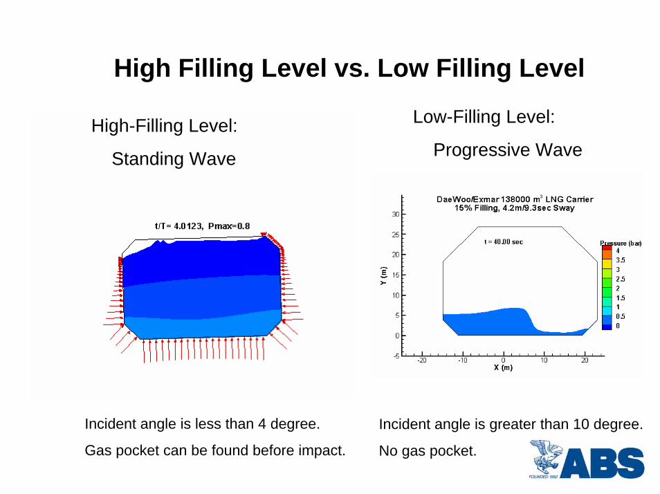
High Filling Level vs. Low Filling Level
Low-Filling Level:
Progressive WaveHigh-Filling Level:
Standing Wave
Incident angle is less than 4 degree.
Gas pocket can be found before impact.
Incident angle is greater than 10 degree.
No gas pocket.
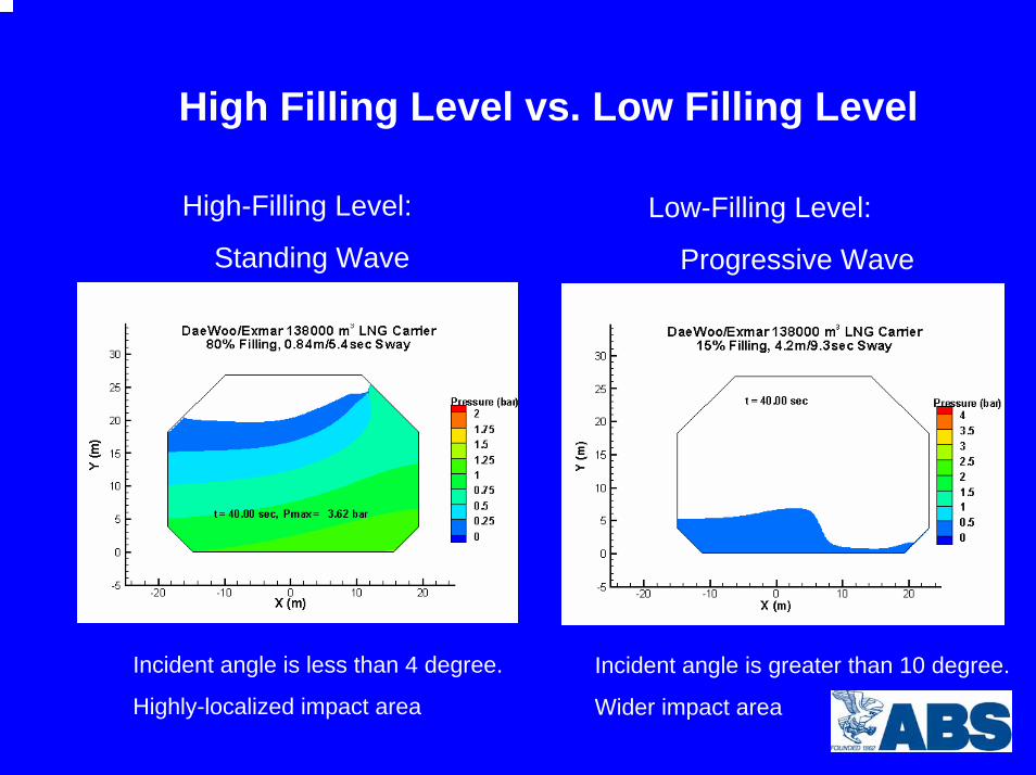
High Filling Level vs. Low Filling Level
High-Filling Level:
Standing Wave
Low-Filling Level:
Progressive Wave
Incident angle is less than 4 degree.
Highly-localized impact area
Incident angle is greater than 10 degree.
Wider impact area
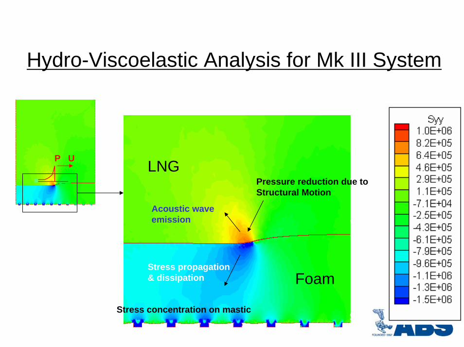
Hydro-Viscoelastic Analysis for Mk III System
LNG
Foam
Pressure reduction due to Structural Motion
Stress propagation & dissipation
Stress concentration on mastic
Acoustic wave emission
P U

Animations
Syy distribution in LNG and CS
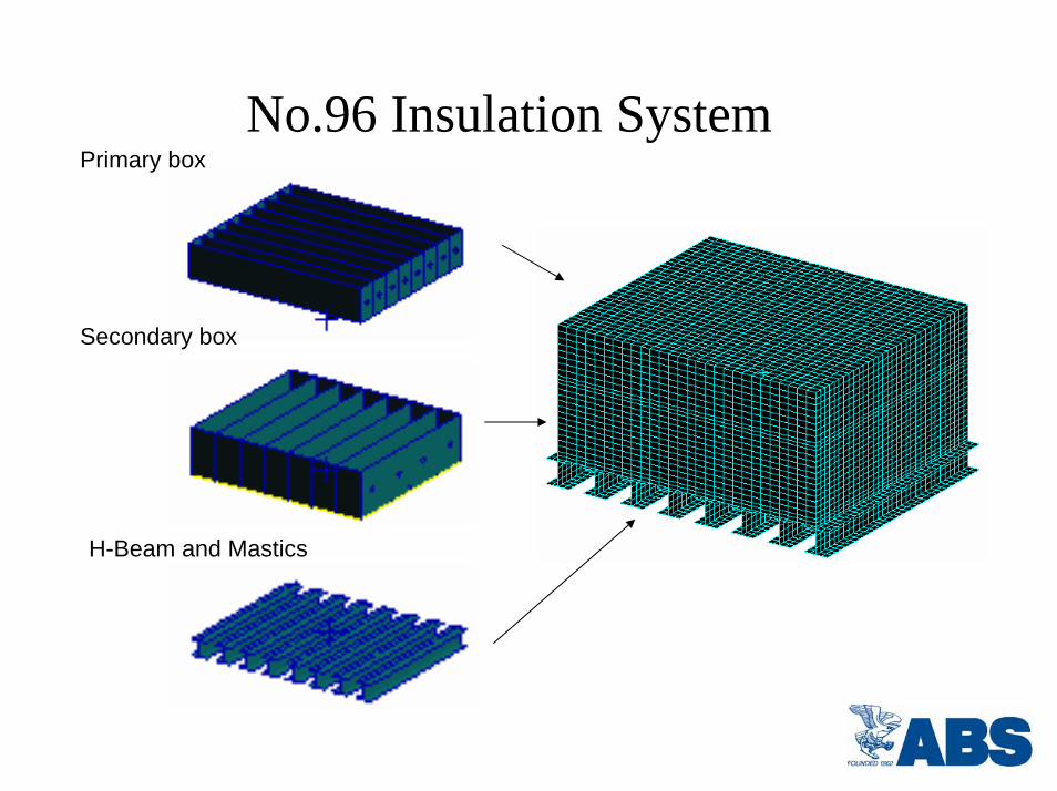
No.96 Insulation System Primary box
Secondary box
H-Beam and Mastics
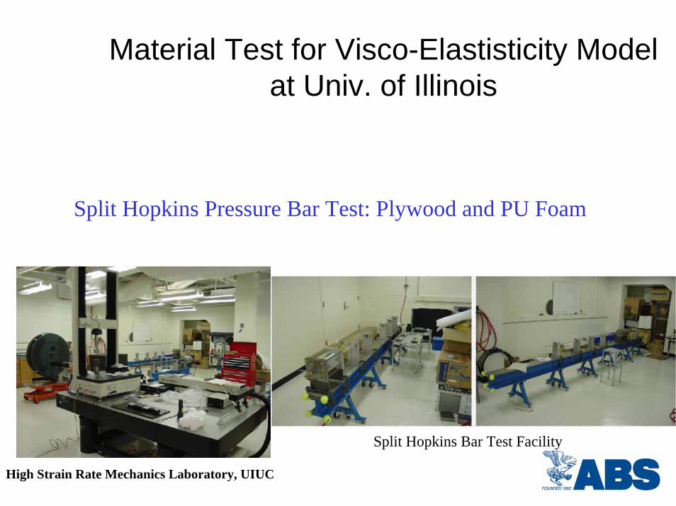
Material Test for Visco-Elastisticity Modelat Univ. of Illinois
Split Hopkins Pressure Bar Test: Plywood and PU Foam
Split Hopkins Bar Test Facility
High Strain Rate Mechanics Laboratory, UIUC

Schematics of Split Hopkins Pressure Bar

Drop Test Facility and Model

GTT Drop Test for Corrugation

Dry Drop Test by GTT
•Full-Scale Mark III Insulation Model
•Failure Mode of Insulation System
•Fracture and Crack Prapagation
⇓
Impact Strength in terms of•Measured Impact Pressure
•Impact Strength Simulation by Visco-Elastic Fracture Analysis

ABS Sloshing Analysis: Pump Tower
Load considered:
•Inertial Load due to ship motion
•Thermal Load
•Sloshing Load
Sloshing Load •Morrison force
•Nonlinear time-domain simulation
•Instantaneous maximum load
Structural analysis & Code check
NASTRAN, SACS, API Code
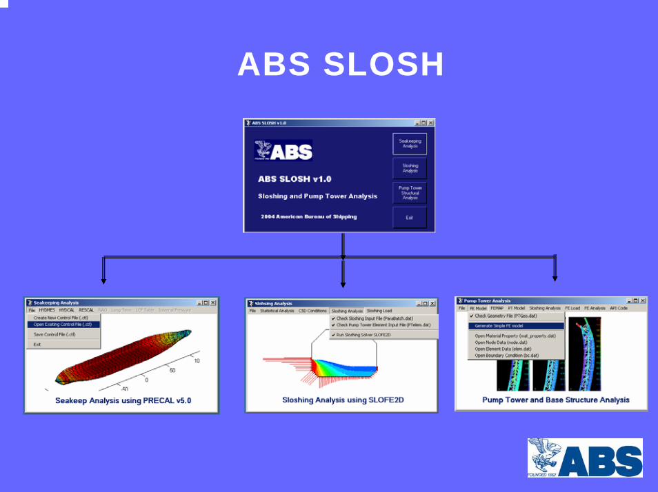
ABS SLOSH
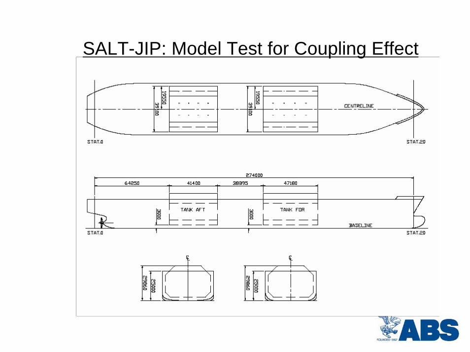
SALT-JIP: Model Test for Coupling Effect

Coupling Effect of Ship Motion and Sloshing
• Strength of the Containment System, Pump Tower and Base Support at Certain Limit of the Sea State
• Extension to the Severe Sea State Condition
• Nonlinear Ship Motion
• NLOAD3D
• Three-Dimensional Effect
• Arbitrary FLVL Combination

Alternative Propulsion(Existing fleet is all steam turbine)
Propulsion efficiency
New technology developments
• Dual fuel - Natural Gas & Fuel Oil• Slow & medium speed diesels & gas turbine
• Shipboard re-liquefaction plants
Class societies offering technical guidance for alternative propulsion.
ABS Guide for Design and Installation of Dual Fuel Engines.
Propulsion For Next Generation LNG CarriersPropulsion For Next Generation LNG Carriers

Global FE Model for Vibration Analysis

Containment system in Global Finite Element model
Containment System was represented in Global FE model as idealized homogeneous elements.
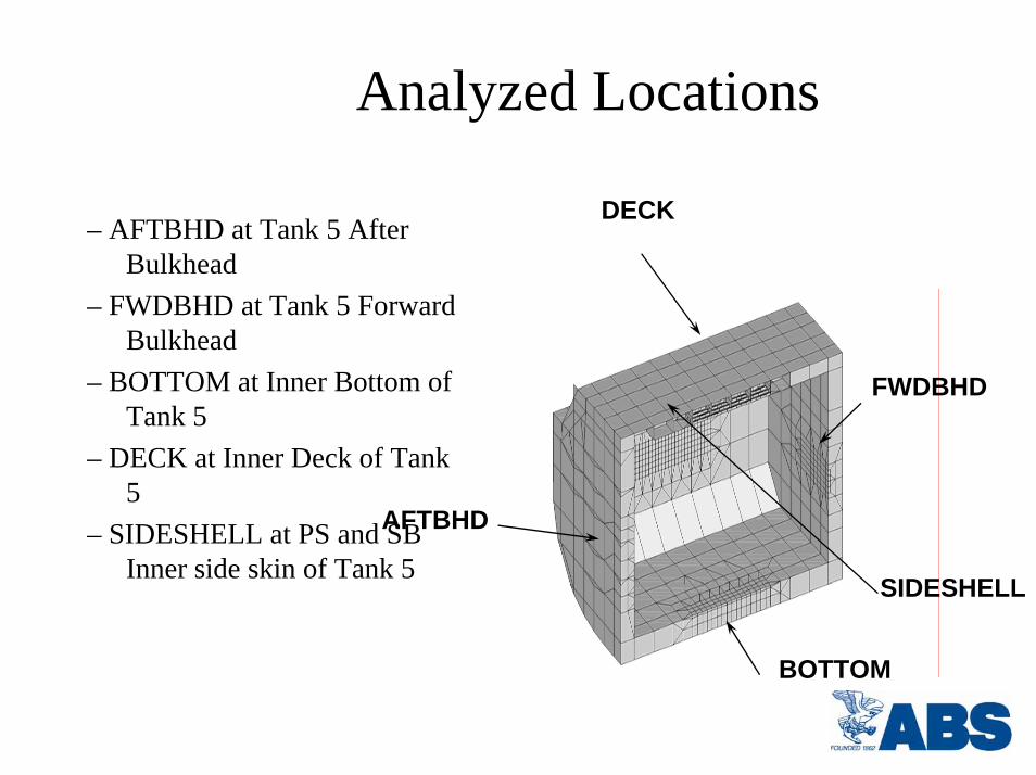
Analyzed Locations
DECK
AFTBHD
BOTTOM
FWDBHD
SIDESHELL
– AFTBHD at Tank 5 After Bulkhead
– FWDBHD at Tank 5 Forward Bulkhead
– BOTTOM at Inner Bottom of Tank 5
– DECK at Inner Deck of Tank 5
– SIDESHELL at PS and SB Inner side skin of Tank 5

Containment System Finite Element Model
Layer 1 – MasticLayer 2 – PlywoodLayer 3 – Secondary Foam Layer 4 – Triplex MembraneLayer 5 – Primary FoamLayer 6 – PlywoodLayer 7 – Steel Membrane.
Dynamic Shaft Alignment Analysis
Information to be Investigated
• Bearing reaction loads • Misalignment at the aft stern tube bearing• Bending curvature• Stresses in shafting

Considering the Effect for
• Hull deflections• Thermal displacement• Buoyancy• Bearing wear down for existing vessel• Propeller thrust

Shafting Alignment Measurements

Approval in Priciple (AIP) of ConocoPhillips Prism Tank Ship 225,000 m3
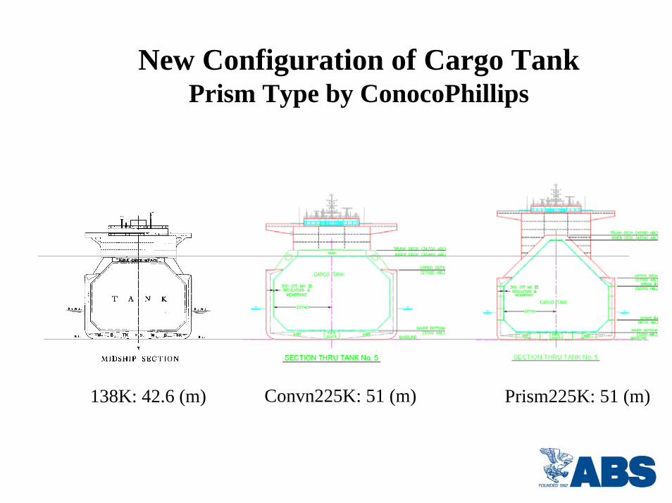
New Configuration of Cargo TankPrism Type by ConocoPhillips
Convn225K: 51 (m) Prism225K: 51 (m)138K: 42.6 (m)

Artic Route Operation
• Murmansk (Russia) to GOM via Arctic seas (Iceland)

Artic Route Operation
• Sloshing Impact Calculation and Model Test in the Arctic Evironmental Condition
• ICE Class LNGC including Sideshell & Propulsion Requirement
• Containment System Assessment in Ice Breaking Operation for Arctic Class LNGC

LNG Core Technology
• Membrane Fatigue Analysis• Pump Tower Vibration and Fatigue Analysis• Multi Tanks and 3-D Sloshing Calculation• Hull Temperature Distribution Analysis• Offshore Loading & Offloading System• Ice Breaking Impact Analysis for Hull and
Containment System
Class Role for LNG Transportation• Develop and Set Standards (Ex: ABS Guide for
Membrane Tank LNG Vessels, Offshore Terminals)
• AIP and Third Party Independent Verification Agent
• Enabling LNG Designers and Operators to meet the New Technical Standards
• Enhancing Safety of the Handling of LNG with Integrated Approach that considers Production, Storage, Transportation, Discharge and Regasfication

Thank You