Embed Size (px)
Citation preview

Lead SealCementing Casing Patch
Manual F645
Manual F645 • Logan Lead Seal Cementing Casing Patch • Page 1
Logan Lead Seal Cementing Casing PatchOverview................................................................................2Uses ......................................................................................2Construction ..........................................................................2Tool Illustration.......................................................................3Operation...............................................................................4 To Release From a Fish.....................................................4Maintenance ..........................................................................5Disassembly ..........................................................................5Assembly ...............................................................................5Calculated Strength Data ......................................................6Specifications and Parts Lists..........................................7 – 9
Contents
1 • Logan Lead Seal Cementing Casing Patch
LEgAL NOTICEAll references to Bowen® part numbers in this literature are used to identify interchangeable tools and parts. Reference to such tools and parts does not imply that Logan Oil Tools is a licensee or is in any way affiliated with National Oilwell Varco.Logan Oil Tools does not sell, or offer to sell, National Oilwell Varco (Bowen) products.
“Bowen” is a registered trademark of National Oilwell Varco.
1st Printing, August 2012. Rev. 0
NOTES
Logan Lead Seal Cementing Casing Patch • 10
Page 2 • Logan Lead Seal Cementing Casing Patch • Manual F645
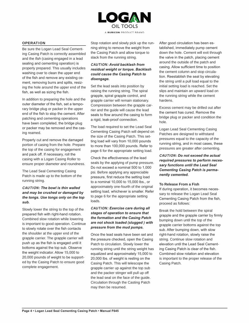
OVERVIEWThe Logan Lead Seal Cementing Cas-ing Patch is an external catch tool that is designed to cement two strings of casing together in a single operation and form a permanent sealed connec-tion between them without restricting the bore of the casing. The Casing Patch becomes a permanent part of the well casing.
In addition to utilizing the field proven, compression-type lead seals of the Logan Lead Seal Casing Patch, the Logan Lead Seal Cementing Casing Patch incorporates a valve system that allows the patch and running string to be cemented in place immediately after the lead seals have been compressed. Since the valve is incorporated into the tool, this eliminates the need for a circu-lating cementing valve or perforations near the Casing Patch.
Patches are available in popular tubing and casing sizes ranging from 2-3/8 to 13-3/8 inches OD.
If hydrogen sulfide is suspected or known to exist in a well, Logan Lead Seal Casing Patches for H2S (hydrogen sulfide) service are also available.
USESLogan Lead Seal Cementing Casing Patches are specifically engineered to replace the upper portion of casing that has been previously cemented in place. It conveniently combines sealing and cementing into one operation, thereby eliminating the time and inconvenience of doing two separate trips.
Logan Lead Seal Cementing Casing Patches are suitable for use in wells that contain fluids or gases harmful to rubber and synthetic packers, and are as strong as the string being repaired.
CONSTRUCTIONLogan Lead Seal Cementing Casing Patches are composed of: a top sub, bowl, grapple carrier, spiral grapple, spi-ral grapple control with set screws, lead seal assembly, stinger, stinger retainer, and a guide. The lead seal assembly consists of two (2) lead seals separated by a center seal ring. There are two (2) end seal rings — one (1) at each end of the assembly.
Two (2) O-rings are installed at the threads where the top sub and guide are connected to the bowl. The lower lead seal nests in a groove on the top end of the packer stinger.
The stinger retainer holds the spiral grapple, spiral grapple control, lead seal assembly, and packer stinger in place.
The bowl is the major working com-ponent of the Lead Seal Cementing Casing Patch. The inside diameter of the bowl features a threaded section that conforms to the exterior threads of the spiral grapple. This design permits any expansion or compression strain to be evenly distributed over the entire working surface of the bowl, spiral grapple, and the fish (casing that is to be engaged during a casing landing operation). Any possible damage to the fish or Lead Seal Cementing Casing Patch is thereby minimized.
The bowl contains and supports the load-bearing spiral grapple. The spiral grapple is the gripping mechanism of the Lead Seal Cementing Casing Patch. The left-handed, helix-shaped spiral grapple conforms to the interior wickers of the bowl. The specially hardened wickers ensure positive engagement with the fish.
As tensile load is applied and increased on the bowl, the spirals between the bowl and the spiral grapple's outside diameter cause the spiral grapple to tightly engage a large area of the fish.
The grapple carrier has external grooves for cement flow, a shoulder at the top of the inside diameter, and threads at the bottom for the stinger retainer.
The spiral grapple control acts as a key that transmits torque from the bowl to the grapple while allowing the grapple to move vertically while inside the bowl during operation. The spiral grapple control is plain — that is, without milling teeth or a pack-off mechanism.
The lowermost component of the Lead Seal Cementing Casing Patch assem-bly is the cut-lipped guide. As the name implies, it guides the fish into the inter-nal gripping mechanism (spiral grapple) of the Casing Patch. The guide also minimizes possible damage to the Cas-ing Patch by blocking the entry of a fish that exceeds its maximum casing O.D. Extra-long guides are available upon request if longer stabilizing length and greater cementing area are desired.
Parts are manufactured from materials that are specifically suitable for each part. Load bearing components are high strength, heat-treated alloy steel to maintain string integrity. The seal assembly is manufactured from pure, unalloyed, fully annealed lead that is particularly suited for use in wells that contain fluids or gases harmful to rub-ber or synthetic packers.
A box connection on the upper end of the Lead Seal Cementing Casing Patch will be cut according to customer specifications.
Logan Lead Seal Cementing Casing Patch • 2

Manual F645 • Logan Lead Seal Cementing Casing Patch • Page 3
Logan Oil Tools reserves the right to change or discontinue designs without notice.
Logan Lead Seal Cementing Casing Patch
Top Sub
O-Ring
Bowl
Grapple Carrier
Guide
Center Seal Ring
Lead Seal
O-Ring
End Seal Ring
Spiral Grapple
Spiral Grapple Control
Control Set Screw
Packer Stinger
Stinger Retainer
End Seal Ring
3 • Logan Lead Seal Cementing Casing Patch
Page 4 • Logan Lead Seal Cementing Casing Patch • Manual F645
Stop rotation and slowly pick up the run-ning string to remove the weight from the Casing Patch and allow torque to slack from the running string.
CAUTION: Avoid backlash from residual weight or torque. Backlash could cause the Casing Patch to disengage.
Set the lead seals into position by raising the running string. The spiral grapple, spiral grapple control, and grapple carrier will remain stationary. Compression between the grapple car-rier and the guide will cause the lead seals to flow around the casing to form a rigid, leak-proof connection.
The load required to set the Lead Seal Cementing Casing Patch will depend on the size of the Casing Patch. This set-ting load will vary from 10,000 pounds to more than 100,000 pounds. Refer to page 6 for the appropriate setting load.
Check the effectiveness of the lead seals by the applying of pump pressure. Do not exceed a nominal 500 to 1,000 psi. Before applying any appreciable pressure, first reduce the setting load to a nominal 10,000 to 15,000 lbs., or approximately one-fourth of the original setting load, whichever is smaller. Refer to page 6 for the appropriate setting loads.
CAUTION: Exercise care during all stages of operation to ensure that the formation and the Casing Patch are not shock loaded (slugged ) with pressure from the mud pumps.
Once the lead seals have been set and the pressure checked, open the Casing Patch to circulation. Slowly lower the running string until the string weight has equalized and approximately 15,000 to 20,000 lbs. of weight is resting on the Casing Patch. This will telescope the grapple carrier up against the top sub and the packer stinger will pull up off the lead seal on the face of the guide. Circulation through the Casting Patch may then be resumed.
After good circulation has been es-tablished, immediately pump cement down the hole. Cement will exit through the valve in the patch, placing cement around the outside of the patch and casing. Allow sufficient time to position the cement column and stop circula-tion. Reestablish the seal by elevating the string until a pull load equal to the initial setting load is reached. Set the slips and maintain an upward load on the running string while the cement hardens.
Excess cement may be drilled out after the cement has cured. Remove the bridge plug or packer and condition the hole.
Logan Lead Seal Cementing Casing Patches are designed to withstand pressures equal to the capacity of the running string, and in most cases, these pressures are greater after cementing.
CAUTION: Do not exceed the actual required pressures to perform neces-sary functions until the Lead Seal Cementing Casing Patch is perma-nently cemented.
To Release From a FishIf during operation, it becomes neces-sary to release the Logan Lead Seal Cementing Casing Patch from the fish, proceed as follows:
Break the hold between the spiral grapple and the grapple carrier by firmly bumping down until the top of thegrapple carrier bottoms against the topsub. After bumping down, with slow right-hand rotation, slowly raise the string. Continue slow rotation and elevation until the Lead Seal Cement-ing Casing Patch is clear of the fish. Combined slow rotation and elevation is important to the proper release of the Casing Patch.
OPERATIONBe sure the Logan Lead Seal Cement-ing Casing Patch is correctly assembled and the fish (casing engaged in a lead sealing and cementing operation) is properly prepared. This usually includes washing over to clean the upper end of the fish and remove any existing ce-ment, removing burrs and splits, resiz-ing the hole around the upper end of the fish, as well as sizing the fish.
In addition to preparing the hole and the outer diameter of the fish, set a tempo-rary bridge plug or packer in the upper end of the fish to stop the cement. After patching and cementing operations have been completed, the bridge plug or packer may be removed and the cas-ing reamed.
Properly cut and remove the damaged portion of casing from the hole. Prepare the top of the casing for engagement and pack off. If necessary, roll the casing with a Logan Casing Roller to ensure proper diameter and roundness.
The Lead Seal Cementing Casing Patch is made up to the bottom of the running string.
CAUTION: The bowl is thin walled and may be crushed or damaged by the tongs. Use tongs only on the top sub.
Slowly lower the string to the top of the prepared fish with right-hand rotation. Combined slow rotation while lowering is important to good operation. Continue to slowly rotate over the fish contacts the shoulder at the upper end of the grapple carrier. The grapple carrier will push up as the fish is engaged until it bottoms against the top sub. Observe the weight indicator. Allow 15,000 to 20,000 pounds of weight to be support-ed by the Casing Patch to ensure good complete engagement.
Logan Lead Seal Cementing Casing Patch • 4
Manual F645 • Logan Lead Seal Cementing Casing Patch • Page 5
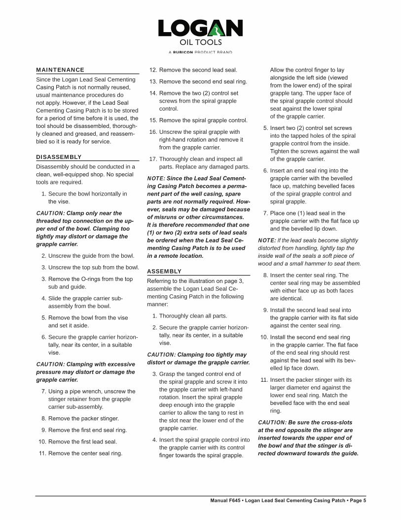
MAINTENANCESince the Logan Lead Seal Cementing Casing Patch is not normally reused, usual maintenance procedures do not apply. However, if the Lead Seal Cementing Casing Patch is to be stored for a period of time before it is used, the tool should be disassembled, thorough-ly cleaned and greased, and reassem-bled so it is ready for service.
DISASSEMBLYDisassembly should be conducted in a clean, well-equipped shop. No special tools are required.
1. Secure the bowl horizontally in the vise.
CAUTION: Clamp only near the threaded top connection on the up-per end of the bowl. Clamping too tightly may distort or damage the grapple carrier.
2. Unscrew the guide from the bowl.
3. Unscrew the top sub from the bowl.
3. Remove the O-rings from the top sub and guide.
4. Slide the grapple carrier sub-assembly from the bowl.
5. Remove the bowl from the vise and set it aside.
6. Secure the grapple carrier horizon- tally, near its center, in a suitable vise.
CAUTION: Clamping with excessive pressure may distort or damage the grapple carrier.
7. Using a pipe wrench, unscrew the stinger retainer from the grapple carrier sub-assembly.
8. Remove the packer stinger.
9. Remove the first end seal ring.
10. Remove the first lead seal.
11. Remove the center seal ring.
12. Remove the second lead seal.
13. Remove the second end seal ring.
14. Remove the two (2) control set screws from the spiral grapple control.
15. Remove the spiral grapple control.
16. Unscrew the spiral grapple with right-hand rotation and remove it
from the grapple carrier.
17. Thoroughly clean and inspect all parts. Replace any damaged parts.
NOTE: Since the Lead Seal Cement-ing Casing Patch becomes a perma-nent part of the well casing, spare parts are not normally required. How-ever, seals may be damaged because of misruns or other circumstances. It is therefore recommended that one (1) or two (2) extra sets of lead seals be ordered when the Lead Seal Ce-menting Casing Patch is to be used in a remote location.
ASSEMBLYReferring to the illustration on page 3,assemble the Logan Lead Seal Ce-menting Casing Patch in the following manner:
1. Thoroughly clean all parts.
2. Secure the grapple carrier horizon- tally, near its center, in a suitable vise.
CAUTION: Clamping too tightly may distort or damage the grapple carrier.
3. Grasp the tanged control end of the spiral grapple and screw it into the grapple carrier with left-hand rotation. Insert the spiral grapple deep enough into the grapple carrier to allow the tang to rest in the slot near the lower end of the grapple carrier.
4. Insert the spiral grapple control intothe grapple carrier with its control
finger towards the spiral grapple.
Allow the control finger to lay alongside the left side (viewed from the lower end) of the spiral
grapple tang. The upper face of the spiral grapple control should seat against the lower spiralof the grapple carrier.
5. Insert two (2) control set screws into the tapped holes of the spiral grapple control from the inside. Tighten the screws against the wall of the grapple carrier.
6. Insert an end seal ring into the grapple carrier with the bevelled face up, matching bevelled faces
of the spiral grapple control and spiral grapple.
7. Place one (1) lead seal in the grapple carrier with the flat face up and the bevelled lip down.
NOTE: If the lead seals become slightly distorted from handling, lightly tap the inside wall of the seals a soft piece of wood and a small hammer to seat them.
8. Insert the center seal ring. Thecenter seal ring may be assembledwith either face up as both faces are identical.
9. Install the second lead seal into the grapple carrier with its flat side
against the center seal ring.
10. Install the second end seal ring in the grapple carrier. The flat face
of the end seal ring should rest against the lead seal with its bev-
elled lip face down.
11. Insert the packer stinger with its larger diameter end against the lower end seal ring. Match the
bevelled face with the end seal ring.
CAUTION: Be sure the cross-slotsat the end opposite the stinger are inserted towards the upper end of the bowl and that the stinger is di-rected downward towards the guide.
5 • Logan Lead Seal Cementing Casing Patch
Page 6 • Logan Lead Seal Cementing Casing Patch • Manual F645
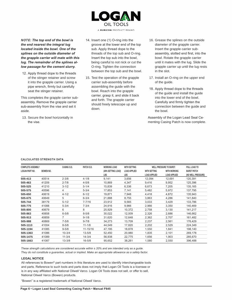
CALCULATED STRENGTH DATA
COMPLETE ASSEMBLY CASING O.D. PATCH O.D. WORKING LOAD WITH SETTING WELL PRESSURE TO BURST: PULL LOAD TOLOGAN PART NO. BOWEN NO. (40% SETTING LOAD) LOAD APPLIED WITH SETTING WITH WORKING BURST PATCH
LBS LBS LOAD APPLIED LOAD APPLIED (NO WELL PRESSURE)505-413 40514 2-3/8 4-1/8 9,141 3,656 12,094 12,691 120,391505-463 41209 2-7/8 4-5/8 10,869 4,347 9,416 9,952 125,396505-525 41210 3-1/2 5-1/4 15,839 6,336 6,673 7,205 135,165505-575 40596 4 5-3/4 17,853 7,141 5,482 5,972 137,795505-650 40619 4-1/2 6-1/2 19,871 7,948 4,418 4,872 135,943505-675 40649 5 6-3/4 21,888 8,755 3,863 4,286 141,840505-744 38179 5-1/2 7-7/16 23,912 9,565 3,033 3,429 133,786505-775 41088 5-3/4 7-3/4 24,916 9,966 2,966 3,350 140,469505-800 40679 6 8 25,929 10,372 2,758 3,130 141,217505-863 40858 6-5/8 8-5/8 30,022 12,009 2,326 2,686 146,662505-913 40859 7 9-1/8 31,620 12,648 2,362 2,707 161,482505-988 40869 7-5/8 9-7/8 34,273 13,709 2,237 2,561 176,429505-1113 41004 8-5/8 11-1/8 44,549 17,820 2,202 2,529 224,349505-1194 41085 9-5/8 11-15/16 47,195 18,878 1,550 1,841 198,140505-1363 41086 10-3/4 13-5/8 52,450 20,980 1,835 2,101 269,178505-1475 41089 11-3/4 14-3/4 56,938 22,775 1,656 1,903 285,670505-1663 41087 13-3/8 16-5/8 95,652 38,261 1,580 2,550 396,488
These strength calculations are considered accurate within ± 20% and are intended only as a guide.They do not constitute a guarantee, actual or implied. Make an appropriate allowance as a safety factor.
NOTE: The top end of the bowl is the end nearest the integral lug located inside the bowl. One of the splines on the outside diameter of the grapple carrier will mate with this lug. The remainder of the splines al-low passage for the cement slurry.
12. Apply thread dope to the threads of the stinger retainer and screw it into the grapple carrier. Using a
pipe wrench, firmly but carefully seat the stinger retainer.
This completes the grapple carrier sub- assembly. Remove the grapple carrier sub-assembly from the vise and set it aside.
13. Secure the bowl horizontally in the vise.
14. Insert one (1) O-ring into the groove at the lower end of the top sub. Apply thread dope to the
threads of the top sub and O-ring. Insert the top sub into the bowl,
being careful to not nick or cut the O-ring. Tighten the connection between the top sub and the bowl.
15. Test the operation of the grapplecarrier sub-assembly before assembling the guide with the bowl. Reach into the grapple
carrier, grasp it, and slide it back and forth. The grapple carrier should freely telescope up and down.
16. Grease the splines on the outside diameter of the grapple carrier.Insert the grapple carrier sub-
assembly, slotted end first, into thebowl. Rotate the grapple carrier until it mates with the lug. Slide thegrapple carrier up until the lug rests in the slot.
17. Install an O-ring on the upper end of the guide.
18. Apply thread dope to the threads of the guide and install the guide into the lower end of the bowl.
Carefully and firmly tighten the connection between the guide and the bowl.
Assembly of the Logan Lead Seal Ce-menting Casing Patch is now complete.
Logan Lead Seal Cementing Casing Patch • 6
LEGAL NOTICEAll references to Bowen® part numbers in this literature are used to identify interchangeable tools and parts. Reference to such tools and parts does not imply that Logan Oil Tools is a licensee or is in any way affiliated with National Oilwell Varco. Logan Oil Tools does not sell, or offer to sell, National Oilwell Varco (Bowen) products.
“Bowen” is a registered trademark of National Oilwell Varco.
Manual F645 • Logan Lead Seal Cementing Casing Patch • Page 7
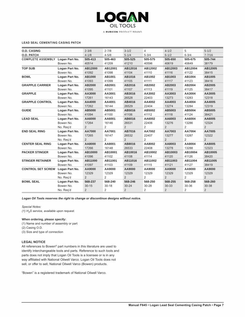
LEAD SEAL CEMENTING CASING PATCH
O.D. CASING 2-3/8 2-7/8 3-1/2 4 4-1/2 5 5-1/2O.D. PATCH 4-1/8 4-5/8 5-1/4 5-3/4 6-1/2 6-3/4 7-7/16COMPLETE ASSEMBLY Logan Part No. 505-413 505-463 505-525 505-575 505-650 505-675 505-744 Bowen No. 40514 41209 41210 40596 40619 40649 38179
TOP SUB Logan Part No. AB12000 AB12001 AB12016 AB12002 AB12003 AB12004 AB12005 Bowen No. 41092 41098 41104 41110 41116 41122 38415BOWL Logan Part No. AB1000 AB1001 AB1016 AB1002 AB1003 AB1004 AB1005 Bowen No. 41093 41099 41105 41111 41117 41123 38416GRAPPLE CARRIER Logan Part No. AB2000 AB2001 AB2016 AB2002 AB2003 AB2004 AB2005 Bowen No. 41095 41101 41107 41113 41119 41125 38417GRAPPLE Logan Part No. AA3000 AA3001 AB3016 AA3002 AA3003 AA3004 AA3005 Bowen No. 17261 16143 26528 22403 13273 13283 12318GRAPPLE CONTROL Logan Part No. AA4000 AA4001 AB4016 AA4002 AA4003 AA4004 AA4005 Bowen No. 17262 16144 26529 22404 13274 13284 12319GUIDE Logan Part No. AB5000 AB5001 AB5016 AB5002 AB5003 AB5004 AB5005 Bowen No. 41094 41100 41106 41112 41118 41124 38421LEAD SEAL Logan Part No. AA6000 AA6001 AB6016 AA6002 AA6003 AA6004 AA6005 Bowen No. 17264 16146 26531 22406 13276 13286 12324 No. Req’d 2 2 2 2 2 2 2END SEAL RING Logan Part No. AA7000 AA7001 AB7016 AA7002 AA7003 AA7004 AA7005 Bowen No. 17265 16147 26532 22407 13277 13287 12322 No. Req’d 2 2 2 2 2 2 2CENTER SEAL RING Logan Part No. AA8000 AA8001 AB8016 AA8002 AA8003 AA8004 AA8005 Bowen No. 17266 16148 26533 22408 13278 13288 12323PACKER STINGER Logan Part No. AB10000 AB10001 AB10016 AB10002 AB10003 AB10004 AB10005 Bowen No. 41096 41102 41108 41114 41120 41126 38420STINGER RETAINER Logan Part No. AB11000 AB11001 AB11016 AB11002 AB11003 AB11004 AB11005 Bowen No. 41097 41103 41109 41115 41121 41127 38419CONTROL SET SCREW Logan Part No. AA9000 AA9000 AA9000 AA9000 AA9000 AA9000 AA9000 Bowen No. 12329 12329 12329 12329 12329 12329 12329 No. Req’d 2 2 2 2 2 2 2BOWL SEAL Logan Part No. 568-237 568-240 568-246 568-250 568-255 568-258 568-260 Bowen No. 30-15 30-18 30-24 30-28 30-33 30-36 30-38 No. Req’d 2 2 2 2 2 2 2
Logan Oil Tools reserves the right to change or discontinue designs without notice.
Special Notes:(1) H2S service, available upon request.
When ordering, please specify:(1) Name and number of assembly or part (2) Casing O.D. (3) Size and type of connection
7 • Logan Lead Seal Cementing Casing Patch
LEGAL NOTICEAll references to Bowen® part numbers in this literature are used to identify interchangeable tools and parts. Reference to such tools and parts does not imply that Logan Oil Tools is a licensee or is in any way affiliated with National Oilwell Varco. Logan Oil Tools does not sell, or offer to sell, National Oilwell Varco (Bowen) products.
“Bowen” is a registered trademark of National Oilwell Varco.
Page 8 • Logan Lead Seal Cementing Casing Patch • Manual F645
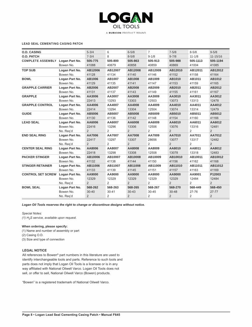
LEAD SEAL CEMENTING CASING PATCH
O.D. CASING 5-3/4 6 6-5/8 7 7-5/8 8-5/8 9-5/8O.D. PATCH 7-3/4 8 8-5/8 9-1/8 9-7/8 11-1/8 11-15/16COMPLETE ASSEMBLY Logan Part No. 505-775 505-800 505-863 505-913 505-988 505-1113 505-1194 Bowen No. 41088 40679 40858 40859 40869 41004 41085
TOP SUB Logan Part No. AB12006 AB12007 AB12008 AB12009 AB12010 AB12011 AB12012 Bowen No. 41128 41134 41140 41146 41152 41158 41164BOWL Logan Part No. AB1006 AB1007 AB1008 AB1009 AB1010 AB1011 AB1012 Bowen No. 41129 41135 41141 41147 41153 41159 41165GRAPPLE CARRIER Logan Part No. AB2006 AB2007 AB2008 AB2009 AB2010 AB2011 AB2012 Bowen No. 41131 41137 41143 41149 41155 41161 41167GRAPPLE Logan Part No. AA3006 AA3007 AA3008 AA3009 AA3010 AA3011 AA3012 Bowen No. 22413 13293 13303 12503 13073 13313 12478GRAPPLE CONTROL Logan Part No. AA4006 AA4007 AA4008 AA4009 AA4010 AA4011 AA4012 Bowen No. 22414 13294 13304 12504 13074 13314 12479GUIDE Logan Part No. AB5006 AB5007 AB5008 AB5009 AB5010 AB5011 AB5012 Bowen No. 41130 41136 41142 41148 41154 41160 41166LEAD SEAL Logan Part No. AA6006 AA6007 AA6008 AA6009 AA6010 AA6011 AA6012 Bowen No. 22416 13296 13306 12506 13076 13316 12481 No. Req’d 2 2 2 2 2 2 2END SEAL RING Logan Part No. AA7006 AA7007 AA7008 AA7009 AA7010 AA7011 AA7012 Bowen No. 22417 13297 13307 28656 13077 13317 12482 No. Req’d 2 2 2 2 2 2 2CENTER SEAL RING Logan Part No. AA8006 AA8007 AA8008 AA8009 AA8010 AA8011 AA8012 Bowen No. 22418 13298 13308 12508 13078 13318 12483PACKER STINGER Logan Part No. AB10006 AB10007 AB10008 AB10009 AB10010 AB10011 AB10012 Bowen No. 41132 41138 41144 41150 41156 41162 41168STINGER RETAINER Logan Part No. AB11006 AB11007 AB11008 AB11009 AB11010 AB11011 AB11012 Bowen No. 41133 41139 41145 41151 41157 41163 41169CONTROL SET SCREW Logan Part No. AA9000 AA9000 AA9000 AA9000 AA9000 AA9001 P12003 Bowen No. 12329 12329 12329 12329 12329 12484 12484 No. Req’d 2 2 2 2 2 2 2BOWL SEAL Logan Part No. 568-262 568-263 568-265 568-267 568-270 568-449 568-450 Bowen No. 30-40 30-41 30-43 30-45 30-48 27-76 27-77 No. Req’d 2 2 2 2 2 2 2
Logan Oil Tools reserves the right to change or discontinue designs without notice.
Special Notes:(1) H2S service, available upon request.
When ordering, please specify:(1) Name and number of assembly or part (2) Casing O.D. (3) Size and type of connection
Logan Lead Seal Cementing Casing Patch • 8
LEGAL NOTICEAll references to Bowen® part numbers in this literature are used to identify interchangeable tools and parts. Reference to such tools and parts does not imply that Logan Oil Tools is a licensee or is in any way affiliated with National Oilwell Varco. Logan Oil Tools does not sell, or offer to sell, National Oilwell Varco (Bowen) products.
“Bowen” is a registered trademark of National Oilwell Varco.
Manual F645 • Logan Lead Seal Cementing Casing Patch • Page 9
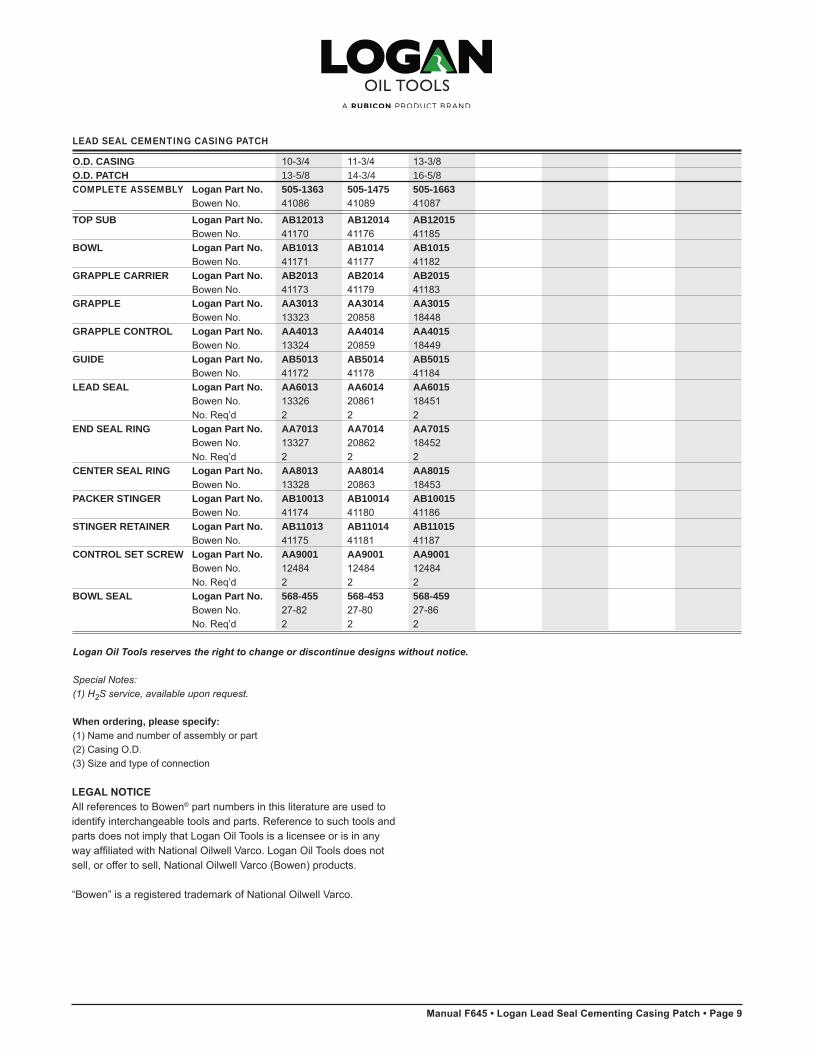
LEAD SEAL CEMENTING CASING PATCH
O.D. CASING 10-3/4 11-3/4 13-3/8 O.D. PATCH 13-5/8 14-3/4 16-5/8COMPLETE ASSEMBLY Logan Part No. 505-1363 505-1475 505-1663 Bowen No. 41086 41089 41087
TOP SUB Logan Part No. AB12013 AB12014 AB12015 Bowen No. 41170 41176 41185BOWL Logan Part No. AB1013 AB1014 AB1015 Bowen No. 41171 41177 41182GRAPPLE CARRIER Logan Part No. AB2013 AB2014 AB2015 Bowen No. 41173 41179 41183GRAPPLE Logan Part No. AA3013 AA3014 AA3015 Bowen No. 13323 20858 18448GRAPPLE CONTROL Logan Part No. AA4013 AA4014 AA4015 Bowen No. 13324 20859 18449GUIDE Logan Part No. AB5013 AB5014 AB5015 Bowen No. 41172 41178 41184LEAD SEAL Logan Part No. AA6013 AA6014 AA6015 Bowen No. 13326 20861 18451 No. Req’d 2 2 2END SEAL RING Logan Part No. AA7013 AA7014 AA7015 Bowen No. 13327 20862 18452 No. Req’d 2 2 2CENTER SEAL RING Logan Part No. AA8013 AA8014 AA8015 Bowen No. 13328 20863 18453PACKER STINGER Logan Part No. AB10013 AB10014 AB10015 Bowen No. 41174 41180 41186STINGER RETAINER Logan Part No. AB11013 AB11014 AB11015 Bowen No. 41175 41181 41187CONTROL SET SCREW Logan Part No. AA9001 AA9001 AA9001 Bowen No. 12484 12484 12484 No. Req’d 2 2 2BOWL SEAL Logan Part No. 568-455 568-453 568-459 Bowen No. 27-82 27-80 27-86 No. Req’d 2 2 2
Logan Oil Tools reserves the right to change or discontinue designs without notice.
Special Notes:(1) H2S service, available upon request.
When ordering, please specify:(1) Name and number of assembly or part (2) Casing O.D. (3) Size and type of connection
9 • Logan Lead Seal Cementing Casing Patch
LEGAL NOTICEAll references to Bowen® part numbers in this literature are used to identify interchangeable tools and parts. Reference to such tools and parts does not imply that Logan Oil Tools is a licensee or is in any way affiliated with National Oilwell Varco. Logan Oil Tools does not sell, or offer to sell, National Oilwell Varco (Bowen) products.
“Bowen” is a registered trademark of National Oilwell Varco.

Page 10 • Logan Lead Seal Cementing Casing Patch • Manual F645
Logan Lead Seal Cementing Casing PatchOverview................................................................................2Uses ......................................................................................2Construction ..........................................................................2Tool Illustration.......................................................................3Operation...............................................................................4 To Release From a Fish.....................................................4Maintenance ..........................................................................5Disassembly ..........................................................................5Assembly ...............................................................................5Calculated Strength Data ......................................................6Specifications and Parts Lists..........................................7 – 9
Contents
1 • Logan Lead Seal Cementing Casing Patch
LEGAL NOTICEAll references to Bowen® part numbers in this literature are used to identify interchangeable tools and parts. Reference to such tools and parts does not imply that Logan Oil Tools is a licensee or is in any way affiliated with National Oilwell Varco.Logan Oil Tools does not sell, or offer to sell, National Oilwell Varco (Bowen) products.
“Bowen” is a registered trademark of National Oilwell Varco.
1st Printing, August 2012. Rev. 0
NOTES
Logan Lead Seal Cementing Casing Patch • 10

©2014 Logan Oil Tools12/2014
CORPORATE HEADQUARTERS
Logan International Inc. 7850 North Sam Houston Parkway West, Suite 100Houston, Texas 77064+1 832 386 2500
635 8th Avenue SouthwestSuite 850Calgary, Canada T2P 3M3 403 930 6810 | Fax 403 930 6811
U.S. SALES OFFICES
California 3155 Pegasus Drive Bakersfield, CA 93308-6800 661.387.1449 I Fax 661.387.1624
Louisiana 103 Bluffwood Drive Broussard , LA 70518-3310 337.839.2331 I Fax 337.839.2334
118 Common Court Houma, LA 70360-7982 985.868.7333 I Fax 985.868.7007
North Dakota 4925 Highway 85 South Williston , ND 58801 701.572.0565 I Fax 701.572.0644
Oklahoma 424 South Eagle Lane Oklahoma City, OK 73128-4225 405.782.0625 I Fax 405.782.0760
Pennsylvania 244 Grey Fox Drive, Suite 1 Montoursville , PA 17754-9572 570.546.1066 I Fax 570.546.0388
Texas 1519 South Flournoy Alice TX,78332 361.396.0139 I Fax 361.396.0112
11610 Cutten Road Houston, TX 77066-3008 832.602.2134 I Fax 832.286.4117
11006 Lucerne Street Houston, Texas 77016-1920 281.219.6613 I Fax 281.219.6638
1305 Energy Drive Kilgore, TX 75662-5539 903.984.6700 I Fax 903.984.6755
601 McDonald Odessa, TX 79761-6106 432.580.7414 I Fax 432.580.7656
Utah 1369 South 1100 East Vernal, UT 84078-8600 435.781.2856 I Fax 435.781.2858
INTERNATIONAL STOCKING DISTRIBUTORS
Canada Logan Oil Tools 9755 45th Avenue NW Edmonton , Alberta T6E 5V8 780.433.9957 I Fax 780.468.1979
Colombia Logan Oil Tools Sucursal Colombia Calle 113 No. 7-21 Edificio Teleport Business Park Torre A, Oficina 915 Bogota, Colombia (57.1 ).629.1995 I Fax (57.1 ).612.8357
A Singapore Logan Oil Tools Pte Ltd 54 Loyang Way Singapore 508747 65.65428422 I Fax 65.65420477
United Arab Emirates Logan Oil Tools Jebel Ali Free Zone (South) P.O. Box 23724 Dubai, UAE 971.4.813.8000 I Fax 971.4.813.8001
Woodhouse International P.O. Box 23724 Dubai, UAE 971.4.347.2300 I Fax 971.4.347.4642
United Kingdom Logan Oil Tools, U.K. Ltd. Unit C1 Kintore Business Park Kintore, lnverurie Aberdeenshire AB51 OYQ Scotland +44.1467.631190