Embed Size (px)
Citation preview
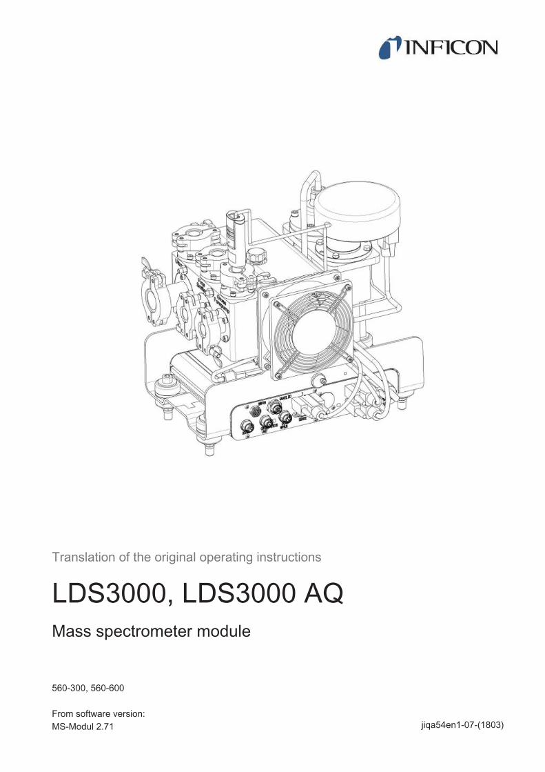
Translation of the original operating instructions
LDS3000, LDS3000 AQMass spectrometer module
jiqa54en1-07-(1803)
560-300, 560-600
From software version:MS-Modul 2.71

INFICON GmbH
Bonner Strasse 498
50968 Cologne, Germany
INFICON Table of Contents
LDS3000-MSM-Operating-instructions-jiqa54en1-07-(1803) iii
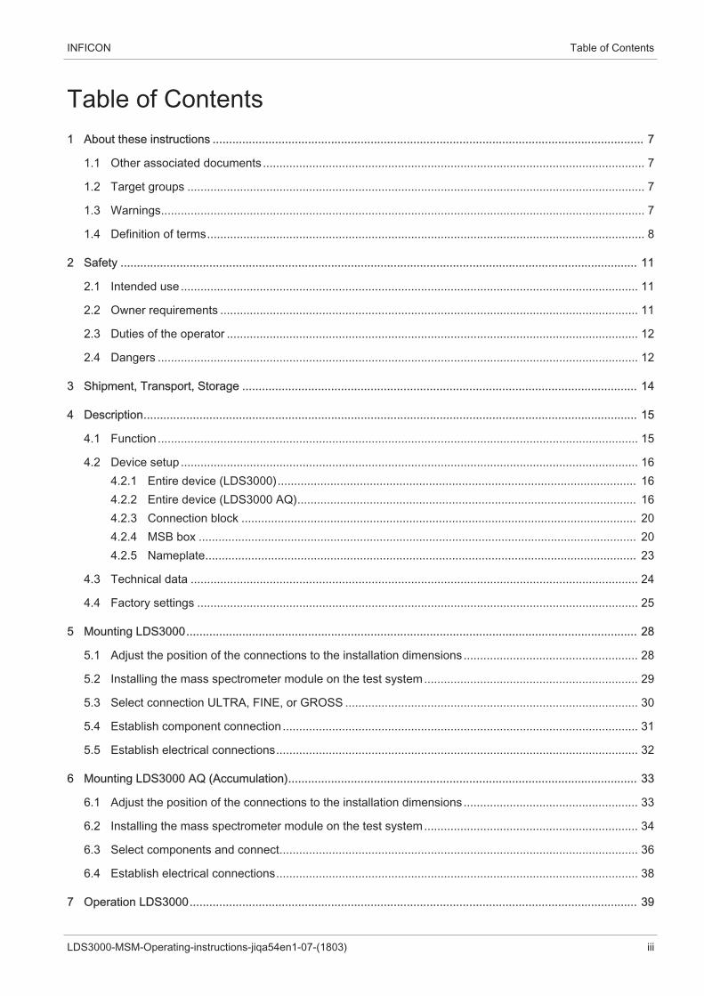
Table of Contents1 About these instructions ................................................................................................................................... 7
1.1 Other associated documents .................................................................................................................... 7
1.2 Target groups ........................................................................................................................................... 7
1.3 Warnings................................................................................................................................................... 7
1.4 Definition of terms..................................................................................................................................... 8
2 Safety ............................................................................................................................................................. 11
2.1 Intended use ........................................................................................................................................... 11
2.2 Owner requirements ............................................................................................................................... 11
2.3 Duties of the operator ............................................................................................................................. 12
2.4 Dangers .................................................................................................................................................. 12
3 Shipment, Transport, Storage ........................................................................................................................ 14
4 Description...................................................................................................................................................... 15
4.1 Function .................................................................................................................................................. 15
4.2 Device setup ........................................................................................................................................... 164.2.1 Entire device (LDS3000)............................................................................................................. 164.2.2 Entire device (LDS3000 AQ)....................................................................................................... 164.2.3 Connection block ........................................................................................................................ 204.2.4 MSB box ..................................................................................................................................... 204.2.5 Nameplate................................................................................................................................... 23
4.3 Technical data ........................................................................................................................................ 24
4.4 Factory settings ...................................................................................................................................... 25
5 Mounting LDS3000......................................................................................................................................... 28
5.1 Adjust the position of the connections to the installation dimensions ..................................................... 28
5.2 Installing the mass spectrometer module on the test system................................................................. 29
5.3 Select connection ULTRA, FINE, or GROSS ......................................................................................... 30
5.4 Establish component connection ............................................................................................................ 31
5.5 Establish electrical connections.............................................................................................................. 32
6 Mounting LDS3000 AQ (Accumulation).......................................................................................................... 33
6.1 Adjust the position of the connections to the installation dimensions ..................................................... 33
6.2 Installing the mass spectrometer module on the test system................................................................. 34
6.3 Select components and connect............................................................................................................. 36
6.4 Establish electrical connections.............................................................................................................. 38
7 Operation LDS3000........................................................................................................................................ 39
Table of Contents INFICON
iv LDS3000-MSM-Operating-instructions-jiqa54en1-07-(1803)
7.1 Switching the device on .......................................................................................................................... 39
7.2 Default settings ....................................................................................................................................... 40
7.3 Selecting a unit for the leak rate ............................................................................................................. 42
7.4 Select device for pressure ...................................................................................................................... 43
7.5 Select Compatibility Mode ...................................................................................................................... 43
7.6 Select operation mode............................................................................................................................ 45
7.7 Select gas type (mass) ........................................................................................................................... 46
7.8 Calibrating the device ............................................................................................................................. 477.8.1 Time and general preferences .................................................................................................... 477.8.2 Internal Calibration Configuration and Start................................................................................ 497.8.3 External Calibration Configuration and Start............................................................................... 507.8.4 Start external dynamic calibration............................................................................................... 527.8.5 External calibration with sniffer line SL3000XL........................................................................... 547.8.6 Check the calibration .................................................................................................................. 55
7.8.6.1 Calibration using the internal calibration leak test.............................................................. 55
7.8.6.2 Calibration using the external calibration leak test............................................................. 557.8.7 Entering the calibration factor ..................................................................................................... 56
7.8.7.1 Calibration factor sniffing.................................................................................................... 56
7.8.7.2 Calibration factor vacuum .................................................................................................. 567.8.8 Setting machine and sniff factor.................................................................................................. 57
7.8.8.1 Setting machine and sniff factor manually ......................................................................... 57
7.8.8.2 Setting machine and sniff factor using machine calibration ............................................... 58
7.9 Starting and stopping the measurement................................................................................................. 58
7.10 Loading and saving parameters ............................................................................................................. 59
7.11 Copying measurement data, deleting measurement data ...................................................................... 60
7.12 Suppressing gas backgrounds with "ZERO" functions ........................................................................... 60
7.13 Measurement result display with signal filters ........................................................................................ 61
7.14 Control of the Gas Ballast Valve of the Backing Pump........................................................................... 62
7.15 Selecting display limits............................................................................................................................ 63
7.16 Setting trigger values .............................................................................................................................. 63
7.17 Setting capillary surveillance .................................................................................................................. 63
7.18 Set the rotation speed of the turbo molecular pump............................................................................... 64
7.19 Cathode Selection .................................................................................................................................. 65
7.20 Settings for the XL sniffer adapter .......................................................................................................... 65
7.21 Resetting the settings ............................................................................................................................. 68
8 Operation LDS3000 AQ (Accumulation)......................................................................................................... 69
8.1 Switching the device on .......................................................................................................................... 69
INFICON Table of Contents
LDS3000-MSM-Operating-instructions-jiqa54en1-07-(1803) v
8.2 Default settings ....................................................................................................................................... 69
8.3 Selecting a unit for the leak rate ............................................................................................................. 70
8.4 Select device for pressure ...................................................................................................................... 71
8.5 Select Compatibility Mode ...................................................................................................................... 71
8.6 Making basic settings via the wizard ...................................................................................................... 73
8.7 Determine peak ...................................................................................................................................... 74
8.8 Store leak rate of calibration leaks.......................................................................................................... 75
8.9 Calibrating the device ............................................................................................................................. 768.9.1 Time and general preferences .................................................................................................... 768.9.2 Entering the calibration factor ..................................................................................................... 778.9.3 Calibration factor vacuum ........................................................................................................... 778.9.4 Calibrating................................................................................................................................... 78
8.10 Perform ZERO........................................................................................................................................ 80
8.11 Setting machine and sniff factor ............................................................................................................. 818.11.1 Setting machine and sniff factor manually .................................................................................. 81
8.12 Carrying out a measurement .................................................................................................................. 82
8.13 Loading and saving parameters ............................................................................................................. 83
8.14 Copying measurement data, deleting measurement data ...................................................................... 83
8.15 Adjust ”Zero time factor AQ” ................................................................................................................... 84
8.16 Selecting display limits............................................................................................................................ 84
8.17 Set the rotation speed of the turbo molecular pump............................................................................... 84
8.18 Cathode Selection .................................................................................................................................. 85
8.19 Resetting the settings ............................................................................................................................. 85
9 Using the expansion module (LDS3000, LDS3000 AQ)................................................................................. 87
9.1 Selecting the type of expansion module ................................................................................................. 87
9.2 Settings for I/O module IO1000 .............................................................................................................. 879.2.1 General interface settings ........................................................................................................... 879.2.2 Assigning inputs and outputs ...................................................................................................... 87
9.2.2.1 Assigning the digital inputs of the I/O module .................................................................... 95
9.2.2.2 Assigning the digital outputs of the I/O module.................................................................. 98
9.3 Settings for bus module BM1000.......................................................................................................... 100
10 Warning and error messages (LDS3000, LDS3000 AQ).............................................................................. 101
10.1 Illustration of error codes with the help of the status LEDs................................................................... 109
11 Operating CU1000 (optional)........................................................................................................................ 110
11.1 Touchscreen elements ......................................................................................................................... 11011.1.1 Measurement display elements ................................................................................................ 110
Table of Contents INFICON
vi LDS3000-MSM-Operating-instructions-jiqa54en1-07-(1803)
11.2 Elements of the error and warning display ........................................................................................... 113
11.3 Settings and functions .......................................................................................................................... 11311.3.1 Touch screen settings............................................................................................................... 11311.3.2 Operator types and authorizations............................................................................................ 117
11.3.2.1 Logging out the operator .................................................................................................. 11811.3.3 Functions .................................................................................................................................. 118
11.3.3.1 Resetting the settings....................................................................................................... 118
11.3.3.2 Recording data................................................................................................................. 119
11.3.3.3 Calling up information ...................................................................................................... 12011.3.4 Updating the software ............................................................................................................... 123
11.3.4.1 Updating the software of the control unit.......................................................................... 123
11.3.4.2 Checking and updating the software version of the MSB box.......................................... 123
11.3.4.3 Updating the software of the I/O module.......................................................................... 124
12 Maintenance ................................................................................................................................................. 126
12.1 Maintenance at INFICON ..................................................................................................................... 126
12.2 General maintenance information......................................................................................................... 126
12.3 Maintenance plan ................................................................................................................................. 127
12.4 Maintenance work................................................................................................................................. 12812.4.1 Change operating fluid reservoir of turbo molecular pump....................................................... 128
13 Decommissioning the measuring instrument................................................................................................ 133
13.1 Shutting down the leak detector ........................................................................................................... 133
13.2 Disposing of the mass spectrometer module........................................................................................ 133
13.3 Returning the mass spectrometer module............................................................................................ 133
14 Appendix....................................................................................................................................................... 134
14.1 CE Declaration of Conformity ............................................................................................................... 134
14.2 Declaration of Incorporation.................................................................................................................. 135
14.3 Declaration of Contamination ............................................................................................................... 136
INFICON About these instructions | 1
LDS3000-MSM-Operating-instructions-jiqa54en1-07-(1803) 7 / 138
1 About these instructionsThis document applies to the software version stated on the title page.
Product names may occur in the document, which are added for identification pur-poses only and belong to the respective owner of the rights.
This operating manual describes the installation and operation of the LDS3000 massspectrometer module. It is available in two variants:
• LDS3000
• LDS3000 AQ (accumulation), switchable to all other operating modes.
1.1 Other associated documentsOperating Manual Control Unit CU1000 jina54
Operating instructions bus module jiqb10
Operating instructions I/O module jiqc10
Operating instructions XL sniffer adapter jinxa54
Interface protocols jira54
1.2 Target groupsThese operating instructions are intended for the owner and for technically qualifiedpersonnel with experience in leak detection technology and integration of leak detec-tion devices in leak detection systems. In addition, the installation and use of the de-vice require knowledge of electronic interfaces.
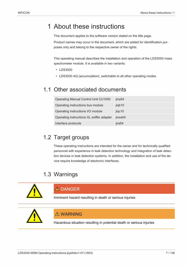
1.3 Warnings
DANGER
Imminent hazard resulting in death or serious injuries
WARNING
Hazardous situation resulting in potential death or serious injuries
1 | About these instructions INFICON
8 / 138 LDS3000-MSM-Operating-instructions-jiqa54en1-07-(1803)
CAUTION
Hazardous situation resulting in minor injuries
NOTICE
Hazardous situation resulting in damage to property or the environment
1.4 Definition of terms
Mention of helium in the manual
The device is a helium leak detector. If you want to use a forming gas instead of he-lium to detect the hydrogen contained therein, the information for helium also appliesto hydrogen.
Accumulation
In connection with leak testing, it is about the enrichment of tracer gas over a defin-able period of time. This allows the detection of small leak rates without the use of avacuum chamber. Helium or forming gas can be used.When you talk about "AQ” in this manual, it's about accumulation mode. It is onlyavailable for devices in the AQ version.
Automatic tuning / mass setting
This function adjusts the mass spectrometer so that a maximum leak rate indicator isachieved. In order to detect a maximum ion current with the ion detector, the controlcomputer adjusts the voltage for accelerating the ions within the selected mass rangeaccordingly.
During each calibration, there is an automatic adjusted.
Operation mode
The leak detector distinguishes between the operation modes "vacuum" and "sniffing".With the operation mode "vacuum", generally the tracer gas flows into the test object.The pressure in the test object is less than the ambient pressure.
In the operation mode "sniffing" the tracer gas flows out from the test object and is ex-tracted with a sniffer probe. The pressure in the test object is greater than the ambientpressure.
INFICON About these instructions | 1
LDS3000-MSM-Operating-instructions-jiqa54en1-07-(1803) 9 / 138
FINE
FINE denotes the connection to the turbo molecular pump for inlet pressures up to 0.4mbar. This is also used for the "sniffing" operation mode.
Forming gas
Forming gas is a collective term for gas mixtures of nitrogen and hydrogen.
GROSS
GROSS donates the connection to the turbo molecular pump with the lowest sensitiv-ity. This allows high inlet pressures (up to 15 mbar).
Internal helium background
The measurement system of the leak detector also contains a residual amount of he-lium. This creates an internal measurement signal component (background signal),which overlaps the display of the leak right from the beginning and thus disturbs thesearch for leaks.
So that this background signal can be suppressed, an internal "background suppres-sion" can be activated with the factory settings.
Minimum detectable leak rate
The minimum detectable leak rate which can be detected by the leak detector underideal conditions (< 5 x 10-12 mbar l/s).
ULTRA
ULTRA denotes the connection to the turbo molecular pump for the measurementrange with the highest sensitivity at inlet pressures below 0.4 mbar (adjustable).
Background signal
Helium or hydrogen (as part of water) are natural components of air.
Operation mode "Vacuum": Before any leak detection, a certain amount of the ad-justed tracer gas is already in the volume on the surfaces of the test chamber, supplylines, and even in the leak detector itself. This certain amount of tracer gas generatesa measurement signal which is called the "Background signal". The ongoing evacua-tion of the test chamber continuously reduces this background signal.
Operation mode "Sniffing": Ambient air is continuously fed into the leak detector viathe sniffer line. The amount of helium or hydrogen occurring naturally in air creates aconstant background signal.
1 | About these instructions INFICON
10 / 138 LDS3000-MSM-Operating-instructions-jiqa54en1-07-(1803)
Foreline pressure
Pressure of the backing pressure between the turbo molecular pump and the backingpump.
ZERO
There is helium that is weakly bound to the surfaces of a specimen as a natural part ofthe ambient air and is pumped bit by bit into the measurement system of the leak de-tector. It produces a slowly decreasing measurement signal.
If you want to hide this background signal or the display of existing leaks, then use thefunction ZERO.
INFICON Safety | 2
LDS3000-MSM-Operating-instructions-jiqa54en1-07-(1803) 11 / 138
2 Safety
2.1 Intended useThe device is a modular leak detector for installation in industrial leak testing unit sys-tems. The tracer gases that can be measured with the device are helium and hydro-gen (forming gas).
The LDS3000 is suitable for overpressure and negative pressure testing, whereby inaddition to the test in vacuum, a local test with a sniffer line is also possible.
The LDS3000 AQ is intended for the measurement of test gases when enriched in anexternal measuring chamber, but can also be rebuilt for all other purposes.
► You must install, operate and service the device only in compliance with these oper-ating instructions.
► Comply with application limits, see "Technical Data".
Improper use Avoid the following, non-intended uses:
• Use in radioactive areas
• Pumping down of explosive, aggressive, corrosive, flammable, toxic or reactivesubstances
• Pumping down of condensable fluids and vapors.
• Aspiration of liquids into the device
• Operation with excessive gas loads
• Operation with excessive foreline pressure
• Operation in incorrect gas mode
• Operation at too high ambient temperature
• Flushing with excessive flushing rate
• Usage of the pumps in plants where sudden loads and vibrations or periodicforces act upon the pump
2.2 Owner requirementsThe following notes are for companies or any person who is responsible for the safetyand effective use of the product by the user, employee or third party.
Safety conscious oper-ation
• Operate the device only if it is in perfect technical condition and has no damage.
• Only operate the device in accordance with this instruction manual, in a safety andrisk conscious manner.
• Adhere to the following regulations and observe their compliance:
– Intended use
2 | Safety INFICON
12 / 138 LDS3000-MSM-Operating-instructions-jiqa54en1-07-(1803)
– General applicable safety and accident prevention regulations
– International, national and local standards and guidelines
– Additional device-related provisions and regulations
• Only use original parts or parts approved by the manufacturer.
• Keep this instruction manual available on site.
Personnel qualifica-tions
• Only instructed personnel should be permitted to work with and on the device. Theinstructed personnel must have received training on the device.
• Make sure that authorized personnel have read and understood the operating in-structions and all other applicable documents.
2.3 Duties of the operator• Read, observe, and follow the information in this manual and in the work instruc-
tions provided by the owner. This concerns in particular the safety instructions andwarnings.
• Always observe the complete operating instructions for all work.
• If you have any questions about operation or maintenance that are not answeredin this manual, please contact Customer Service.
2.4 DangersThe measuring instrument was built according to the state-of-the-art and the recog-nized safety regulations. Nevertheless, improper use may result in risk to life and limbon the part of the user or third parties, or damage to the measuring instrument or otherproperty may occur.
Hazards due to liquidsand chemicals
Liquids and chemical substances can damage the instrument.
• Comply with application limits, see "Technical Data".
• Do not suck up liquids with the instrument.
• Keep the hydrogen concentration below 5% to prevent ignition.
Permanent magnets Permanent magnets in the device pose a hazard to health. Cardiac pacemaker maybe affected in their function.
• Keep a sufficient distance from the device.
• Always comply with the distances recommended by the pacemaker manufacturerwithout fail.
Dangers from electricpower
The device is operated with electrical voltages of up to 24 V. Inside the device thereare voltages that are considerably higher. There is a danger to life from the contact ofconductive parts inside the device.
INFICON Safety | 2
LDS3000-MSM-Operating-instructions-jiqa54en1-07-(1803) 13 / 138
• Disconnect the device from the power supply prior to any installation and mainte-nance work. Make sure that the electric power supply cannot reconnected withoutauthorization.
• Before starting the leak test, disconnect electrically operated test objects from thepower supply.
The device contains electric components that can be damaged from high electric volt-age.
• Make sure before connecting to the power supply that the supply voltage is 24 V+/- 5 %.
Kinetic energy If the rotating parts in the turbo molecular pump are blocked because of some dam-age, high centrifugal forces must be absorbed. If this is not successful, the mass spec-trometer module will breakaway and possibly cause damage to property or personalinjury.
• Make sure the mount of the mass spectrometer module is able to absorb a brakingtorque of 820 Nm.
Injury from bursting ob-jects
There is risk of injury from bursting objects causes by a test object notwithstanding thevacuum pressure when a test object is connected.
• Take appropriate precautions.
Danger due to implod-ing measuring chamber
An external measuring chamber connected to an LDS3000 AQ is pumped off at ap-proximately 60 sccm. Within normal measurement times (2 - 30 seconds) no danger-ous negative pressure is generated.
If the measuring chamber is leak-proof, but not vacuum resistant, and continues topump, it may implode. This can occur, for example, in a 1-liter measuring chamber af-ter about 10 minutes.
• Do not continue pumping a measuring chamber after the measuring time has ex-pired.
• Consider suitable protective measures!
3 | Shipment, Transport, Storage INFICON
14 / 138 LDS3000-MSM-Operating-instructions-jiqa54en1-07-(1803)
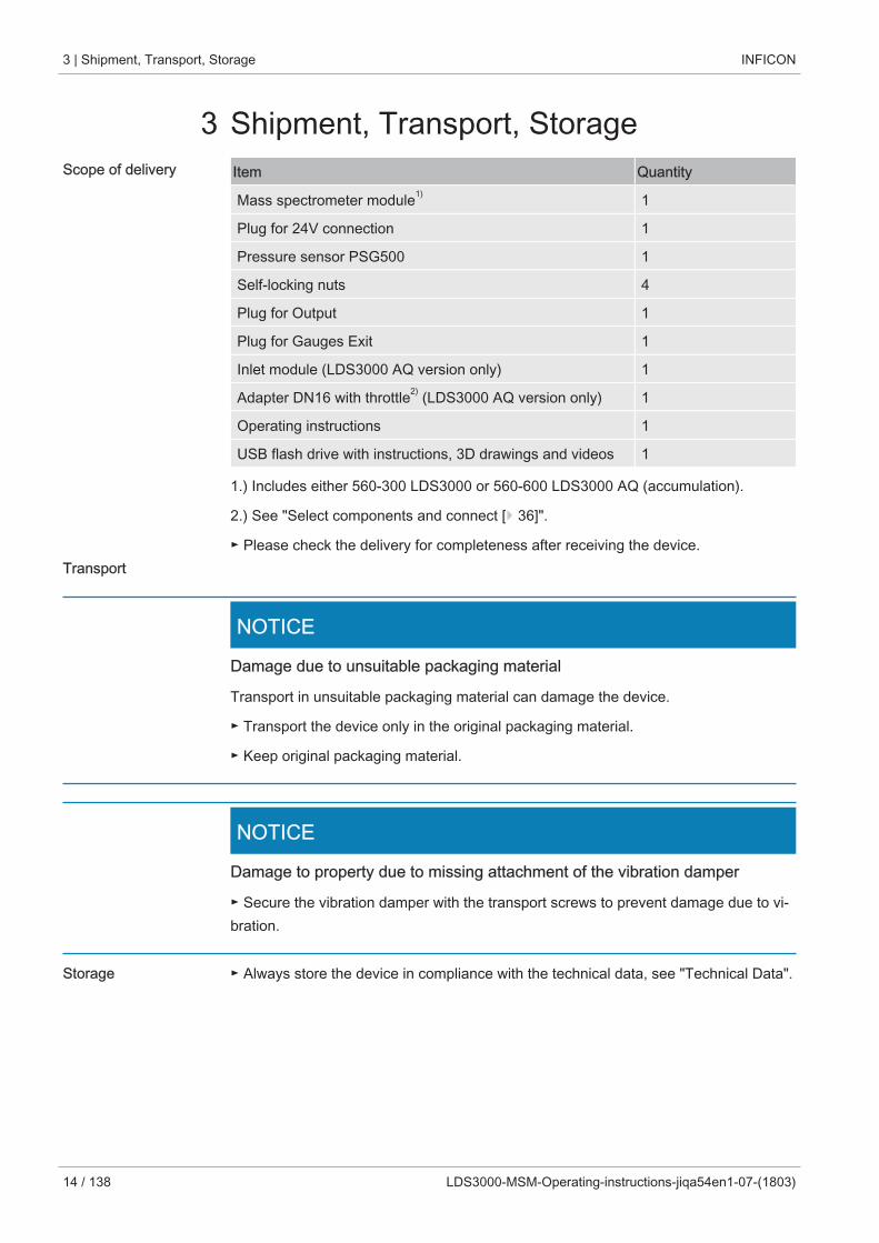
3 Shipment, Transport, StorageScope of delivery Item Quantity
Mass spectrometer module1) 1
Plug for 24V connection 1
Pressure sensor PSG500 1
Self-locking nuts 4
Plug for Output 1
Plug for Gauges Exit 1
Inlet module (LDS3000 AQ version only) 1
Adapter DN16 with throttle2) (LDS3000 AQ version only) 1
Operating instructions 1
USB flash drive with instructions, 3D drawings and videos 1
1.) Includes either 560-300 LDS3000 or 560-600 LDS3000 AQ (accumulation).
2.) See "Select components and connect [} 36]".
► Please check the delivery for completeness after receiving the device.Transport
NOTICE
Damage due to unsuitable packaging material
Transport in unsuitable packaging material can damage the device.
► Transport the device only in the original packaging material.
► Keep original packaging material.
NOTICE
Damage to property due to missing attachment of the vibration damper
► Secure the vibration damper with the transport screws to prevent damage due to vi-bration.
Storage ► Always store the device in compliance with the technical data, see "Technical Data".
INFICON Description | 4
LDS3000-MSM-Operating-instructions-jiqa54en1-07-(1803) 15 / 138
4 Description
4.1 FunctionObjective The mass spectrometer module is a detection device for the test gases helium and hy-
drogen. Integrated in test systems, the device is used to detect gas being emitted froma test object in order to indicate leaks.
The device can be used both as a vacuum leak detector and a sniffer leak detector.Sniffer lines with different lengths are available for the sniffer mode.
Mode AQ (Accumula-tion)
In order to be able to detect small leak rates without the use of a vacuum chamber,devices for the AQ mode are connected to an external measuring chamber. In the ex-ternal measuring chamber, the tracer gas is enriched (accumulation).The test object filled with helium or forming gas under pressure is brought into themeasuring chamber or pressurized in the measuring chamber. If there is a leak in thetest object, the concentration of helium or forming gas in the measuring chamber willincrease. This increase is measured and output as a leak rate.
Device Interfaces The mass spectrometer module is part of the leak detection system LDS3000 andLDS3000 AQ. Es can be operated in a test system together with a bus module or I/Omodule and a data cable without additional INFICON accessories.
The MSB box outputs data on digital interfaces to the control unit CU1000, I/O moduleIO1000 or bus module BM1000.
Other accessories With the available accessories XL sniffer adapter and sniffer line SL3000XL, it is pos-sible to capture leaks at a larger distance from the expected leak if the detection limitis deteriorated (operation in "high flow" mode).
4 | Description INFICON
16 / 138 LDS3000-MSM-Operating-instructions-jiqa54en1-07-(1803)
4.2 Device setup
4.2.1 Entire device (LDS3000)
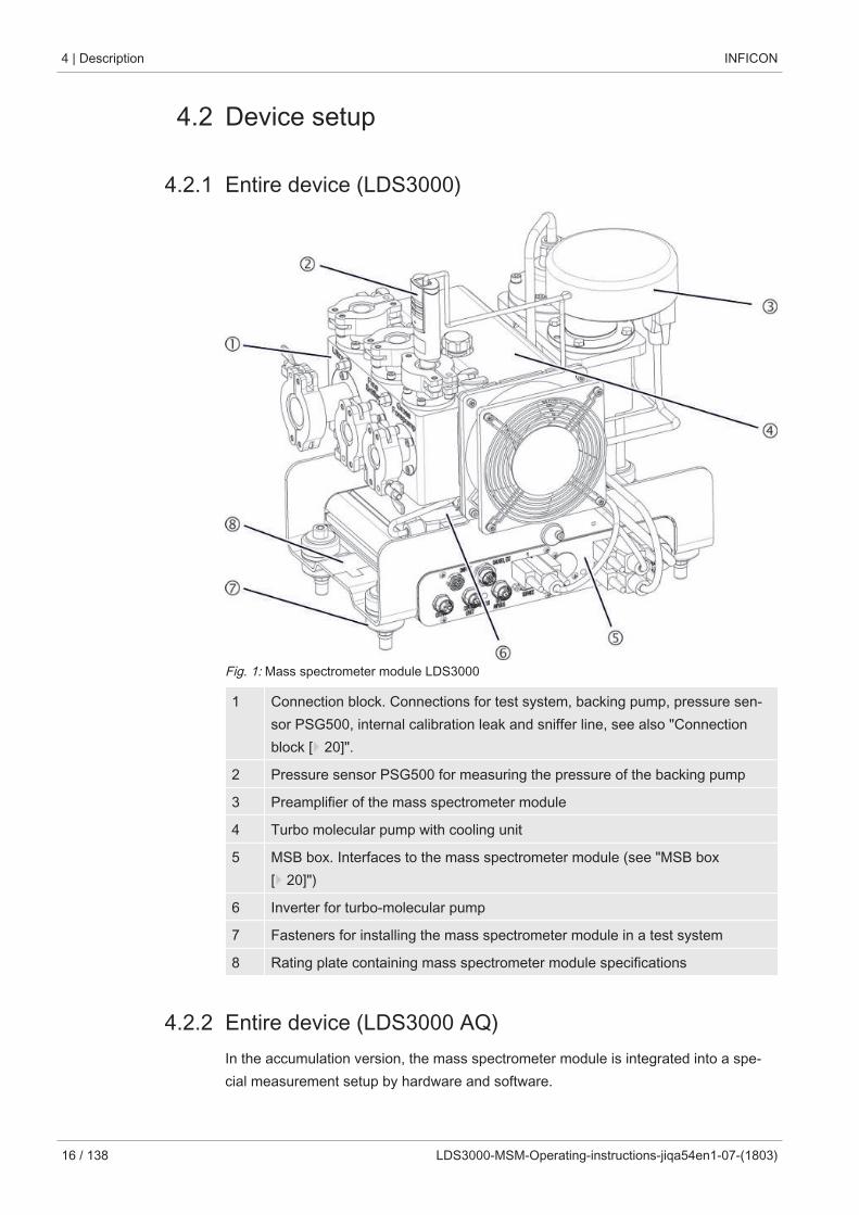
Fig. 1: Mass spectrometer module LDS3000
1 Connection block. Connections for test system, backing pump, pressure sen-sor PSG500, internal calibration leak and sniffer line, see also "Connectionblock [} 20]".
2 Pressure sensor PSG500 for measuring the pressure of the backing pump
3 Preamplifier of the mass spectrometer module
4 Turbo molecular pump with cooling unit
5 MSB box. Interfaces to the mass spectrometer module (see "MSB box[} 20]")
6 Inverter for turbo-molecular pump
7 Fasteners for installing the mass spectrometer module in a test system
8 Rating plate containing mass spectrometer module specifications
4.2.2 Entire device (LDS3000 AQ)In the accumulation version, the mass spectrometer module is integrated into a spe-cial measurement setup by hardware and software.
INFICON Description | 4
LDS3000-MSM-Operating-instructions-jiqa54en1-07-(1803) 17 / 138
312 6 7
14
5
48
49
411
410
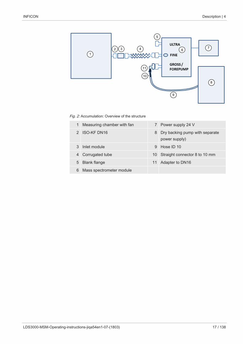
Fig. 2: Accumulation: Overview of the structure
1 Measuring chamber with fan 7 Power supply 24 V
2 ISO-KF DN16 8 Dry backing pump with separatepower supply)
3 Inlet module 9 Hose ID 10
4 Corrugated tube 10 Straight connector 8 to 10 mm
5 Blank flange 11 Adapter to DN16
6 Mass spectrometer module
4 | Description INFICON
18 / 138 LDS3000-MSM-Operating-instructions-jiqa54en1-07-(1803)
2
1
3
34
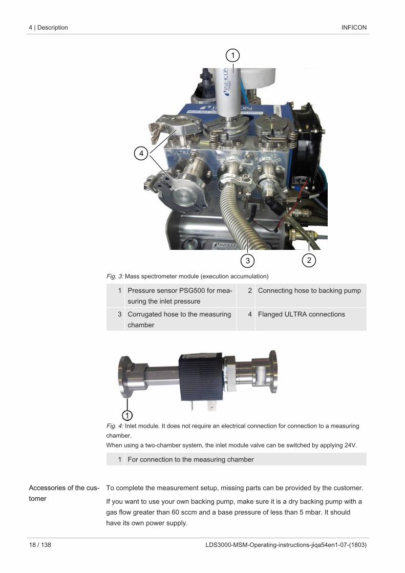
Fig. 3: Mass spectrometer module (execution accumulation)
1 Pressure sensor PSG500 for mea-suring the inlet pressure
2 Connecting hose to backing pump
3 Corrugated hose to the measuringchamber
4 Flanged ULTRA connections
Fig. 4: Inlet module. It does not require an electrical connection for connection to a measuringchamber. When using a two-chamber system, the inlet module valve can be switched by applying 24V.
1 For connection to the measuring chamber
Accessories of the cus-tomer
To complete the measurement setup, missing parts can be provided by the customer.
If you want to use your own backing pump, make sure it is a dry backing pump with agas flow greater than 60 sccm and a base pressure of less than 5 mbar. It shouldhave its own power supply.
INFICON Description | 4
LDS3000-MSM-Operating-instructions-jiqa54en1-07-(1803) 19 / 138
If you want to use your own control unit, please note that the wizard for performing themeasurement settings, calibrating and setting the ZERO function is only located onthe INFICON CU1000 control unit.
See also “Select components and connect [} 36]“.
Optional accessoriesfrom INFICON
With the exception of the measuring chamber, the required parts are also offered byINFICON.
• Control unit CU1000 (including wizard for carrying out important settings)
• I/O1000 (The I/O module is a device interface between a leak detector and an ex-ternal controller)
• BM1000 (The bus module is a device interface between e.g. the MSB box of themass spectrometer module LDS3000 and an external controller.)
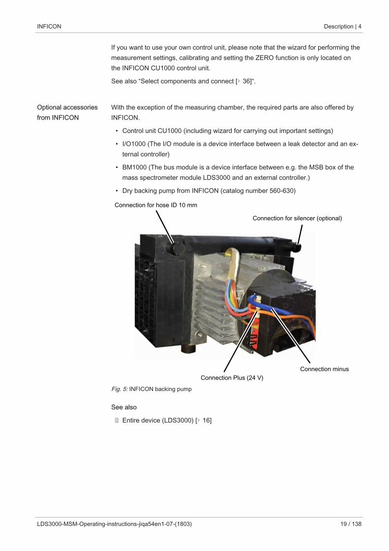
• Dry backing pump from INFICON (catalog number 560-630)
ULTRA
Connection for hose ID 10 mm
Connection for silencer (optional)
Connection Plus (24 V)Connection minus
Fig. 5: INFICON backing pump
See also
2 Entire device (LDS3000) [} 16]
4 | Description INFICON
20 / 138 LDS3000-MSM-Operating-instructions-jiqa54en1-07-(1803)
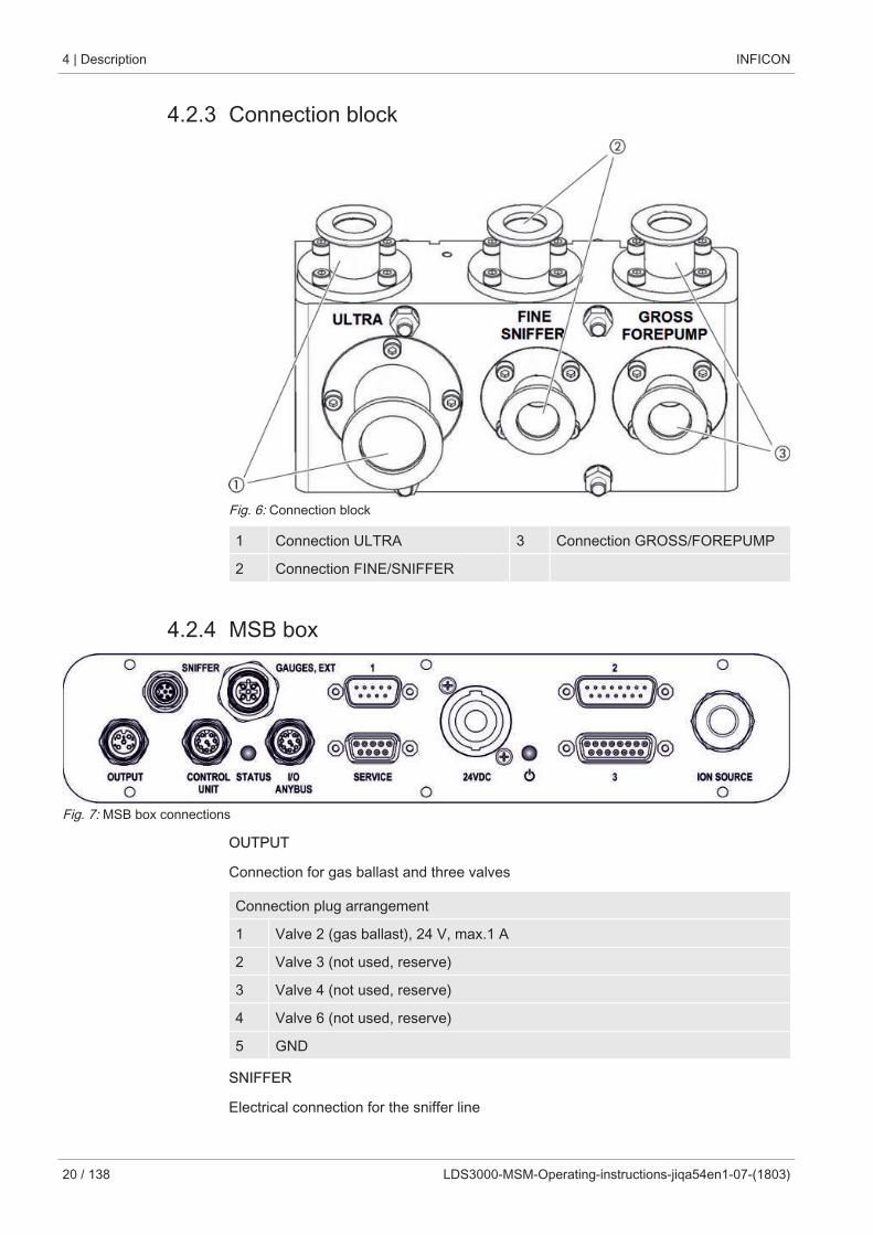
4.2.3 Connection block
Fig. 6: Connection block
1 Connection ULTRA 3 Connection GROSS/FOREPUMP
2 Connection FINE/SNIFFER
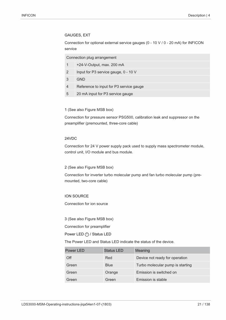
4.2.4 MSB box
Fig. 7: MSB box connections
OUTPUT
Connection for gas ballast and three valves
Connection plug arrangement
1 Valve 2 (gas ballast), 24 V, max.1 A
2 Valve 3 (not used, reserve)
3 Valve 4 (not used, reserve)
4 Valve 6 (not used, reserve)
5 GND
SNIFFER
Electrical connection for the sniffer line
INFICON Description | 4
LDS3000-MSM-Operating-instructions-jiqa54en1-07-(1803) 21 / 138
GAUGES, EXT
Connection for optional external service gauges (0 - 10 V / 0 - 20 mA) for INFICONservice
Connection plug arrangement
1 +24-V-Output, max. 200 mA
2 Input for P3 service gauge, 0 - 10 V
3 GND
4 Reference to input for P3 service gauge
5 20 mA input for P3 service gauge
1 (See also Figure MSB box)
Connection for pressure sensor PSG500, calibration leak and suppressor on thepreamplifier (premounted, three-core cable)
24VDC
Connection for 24 V power supply pack used to supply mass spectrometer module,control unit, I/O module and bus module.
2 (See also Figure MSB box)
Connection for inverter turbo molecular pump and fan turbo molecular pump (pre-mounted, two-core cable)
ION SOURCE
Connection for ion source
3 (See also Figure MSB box)
Connection for preamplifier
Power LED / Status LED
The Power LED and Status LED indicate the status of the device.
Power LED Status LED Meaning
Off Red Device not ready for operation
Green Blue Turbo molecular pump is starting
Green Orange Emission is switched on
Green Green Emission is stable
4 | Description INFICON
22 / 138 LDS3000-MSM-Operating-instructions-jiqa54en1-07-(1803)
Power LED Status LED Meaning
Green Violet Rotation speed of the turbo molecularpump is not within the normal range
Green Error codes ofthe status LED
Different activities of the unit
Green, flashes slowly Supply voltage < 21.6 V
Green, flashes fast Supply voltage > 26.4 V
Green, flashes Off Software is being updated
Green Green, flashes Software is being updated
SERVICE
RS232 connection for INFICON Service
I/O / ANYBUS
CONTROL UNIT
Connection for I/O or bus module or control unit
The connections "I/O Anybus" and "Control Unit" have the same functions. You havethe choice of connecting:
– Control unit CU1000 + I/O module IO1000
– Control unit CU1000 + bus module BM1000
STATUS
Status LED
The Power LED and Status LED indicate the status of the unit.
INFICON Description | 4
LDS3000-MSM-Operating-instructions-jiqa54en1-07-(1803) 23 / 138
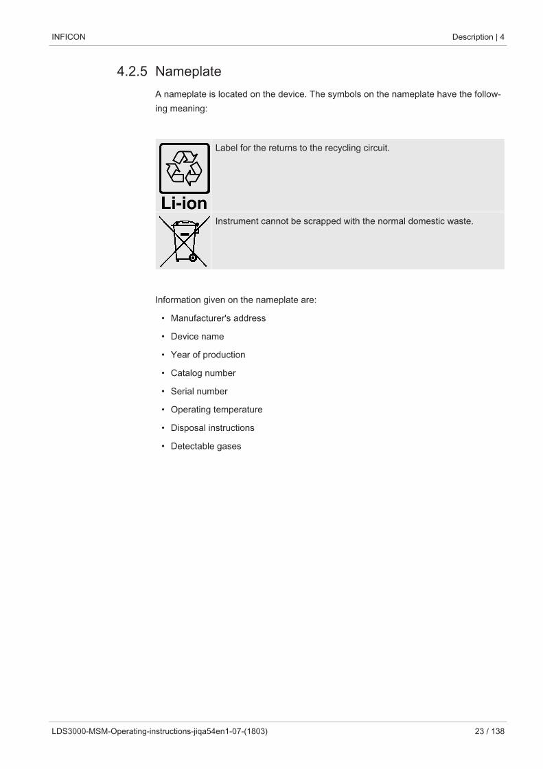
4.2.5 NameplateA nameplate is located on the device. The symbols on the nameplate have the follow-ing meaning:
Label for the returns to the recycling circuit.
Instrument cannot be scrapped with the normal domestic waste.
Information given on the nameplate are:
• Manufacturer's address
• Device name
• Year of production
• Catalog number
• Serial number
• Operating temperature
• Disposal instructions
• Detectable gases
4 | Description INFICON
24 / 138 LDS3000-MSM-Operating-instructions-jiqa54en1-07-(1803)
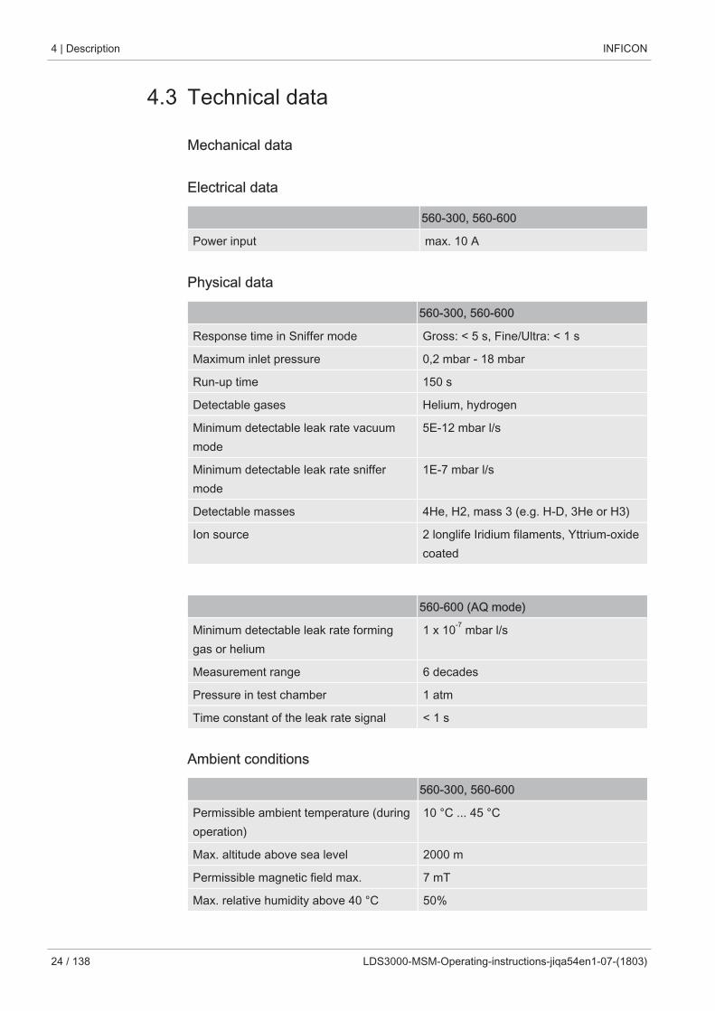
4.3 Technical data
Mechanical data
Electrical data
560-300, 560-600
Power input max. 10 A
Physical data
560-300, 560-600
Response time in Sniffer mode Gross: < 5 s, Fine/Ultra: < 1 s
Maximum inlet pressure 0,2 mbar - 18 mbar
Run-up time 150 s
Detectable gases Helium, hydrogen
Minimum detectable leak rate vacuummode
5E-12 mbar l/s
Minimum detectable leak rate sniffermode
1E-7 mbar l/s
Detectable masses 4He, H2, mass 3 (e.g. H-D, 3He or H3)
Ion source 2 longlife Iridium filaments, Yttrium-oxidecoated
560-600 (AQ mode)
Minimum detectable leak rate forminggas or helium
1 x 10⁻⁷ mbar l/s
Measurement range 6 decades
Pressure in test chamber 1 atm
Time constant of the leak rate signal < 1 s
Ambient conditions
560-300, 560-600
Permissible ambient temperature (duringoperation)
10 °C ... 45 °C
Max. altitude above sea level 2000 m
Permissible magnetic field max. 7 mT
Max. relative humidity above 40 °C 50%
INFICON Description | 4
LDS3000-MSM-Operating-instructions-jiqa54en1-07-(1803) 25 / 138
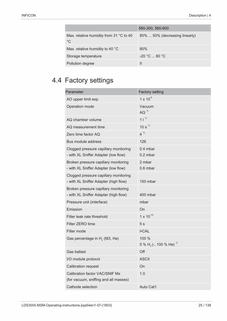
560-300, 560-600
Max. relative humidity from 31 °C to 40°C
80% ... 50% (decreasing linearly)
Max. relative humidity to 40 °C 80%
Storage temperature -20 °C ... 60 °C
Pollution degree II
4.4 Factory settingsParameter Factory setting
AO upper limit exp. 1 x 10⁻⁵
Operation mode VacuumAQ 1)
AQ chamber volume 1 l 1)
AQ measurement time 10 s 1)
Zero time factor AQ 4 1)
Bus module address 126
Clogged pressure capillary monitoring - with XL Sniffer Adapter (low flow)
0.4 mbar0.2 mbar
Broken pressure capillary monitoring - with XL Sniffer Adapter (low flow)
2 mbar0.6 mbar
Clogged pressure capillary monitoring - with XL Sniffer Adapter (high flow) 150 mbar
Broken pressure capillary monitoring - with XL Sniffer Adapter (high flow) 400 mbar
Pressure unit (interface) mbar
Emission On
Filter leak rate threshold 1 x 10⁻¹⁰
Filter ZERO time 5 s
Filter mode I•CAL
Gas percentage in H2 (M3, He) 100 %5 % H2 (-, 100 % He) 1)
Gas ballast Off
I/O module protocol ASCII
Calibration request On
Calibration factor VAC/SNIF Mx(for vacuum, sniffing and all masses)
1.0
Cathode selection Auto Cat1
4 | Description INFICON
26 / 138 LDS3000-MSM-Operating-instructions-jiqa54en1-07-(1803)
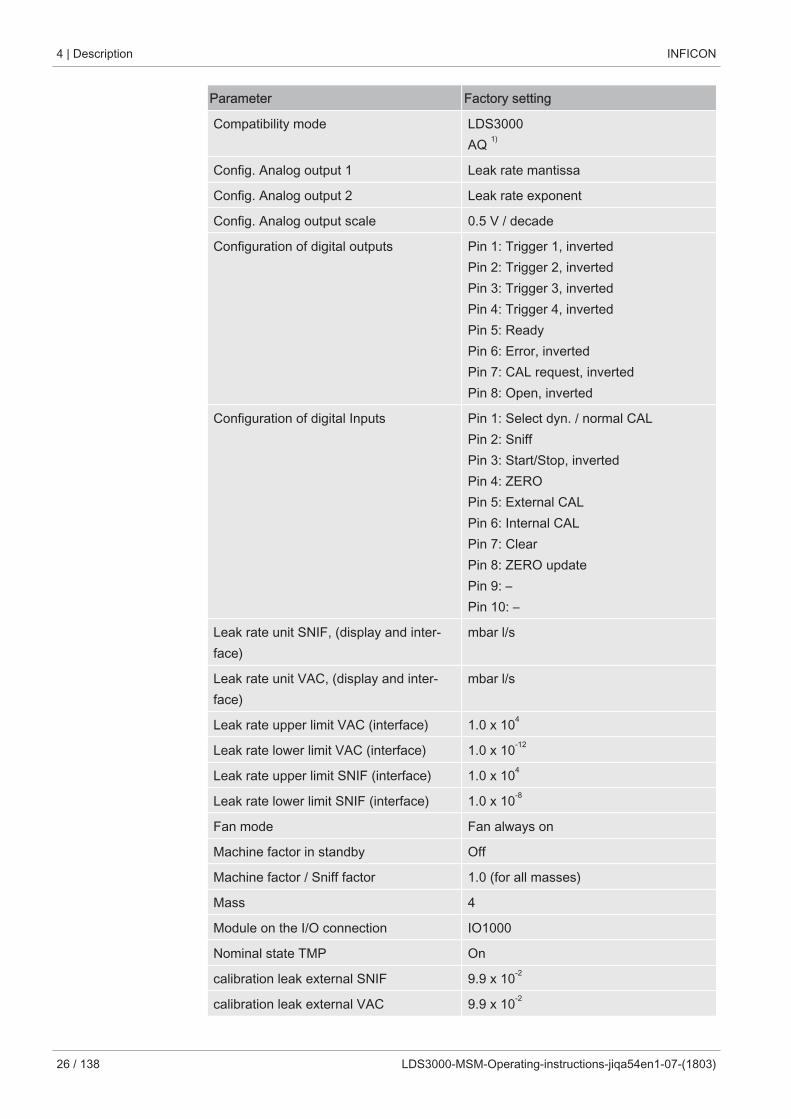
Parameter Factory setting
Compatibility mode LDS3000AQ 1)
Config. Analog output 1 Leak rate mantissa
Config. Analog output 2 Leak rate exponent
Config. Analog output scale 0.5 V / decade
Configuration of digital outputs Pin 1: Trigger 1, invertedPin 2: Trigger 2, invertedPin 3: Trigger 3, invertedPin 4: Trigger 4, invertedPin 5: ReadyPin 6: Error, invertedPin 7: CAL request, invertedPin 8: Open, inverted
Configuration of digital Inputs Pin 1: Select dyn. / normal CALPin 2: SniffPin 3: Start/Stop, invertedPin 4: ZEROPin 5: External CALPin 6: Internal CALPin 7: ClearPin 8: ZERO updatePin 9: –Pin 10: –
Leak rate unit SNIF, (display and inter-face)
mbar l/s
Leak rate unit VAC, (display and inter-face)
mbar l/s
Leak rate upper limit VAC (interface) 1.0 x 10⁴
Leak rate lower limit VAC (interface) 1.0 x 10⁻¹²
Leak rate upper limit SNIF (interface) 1.0 x 10⁴
Leak rate lower limit SNIF (interface) 1.0 x 10⁻⁸
Fan mode Fan always on
Machine factor in standby Off
Machine factor / Sniff factor 1.0 (for all masses)
Mass 4
Module on the I/O connection IO1000
Nominal state TMP On
calibration leak external SNIF 9.9 x 10⁻²
calibration leak external VAC 9.9 x 10⁻²
INFICON Description | 4
LDS3000-MSM-Operating-instructions-jiqa54en1-07-(1803) 27 / 138
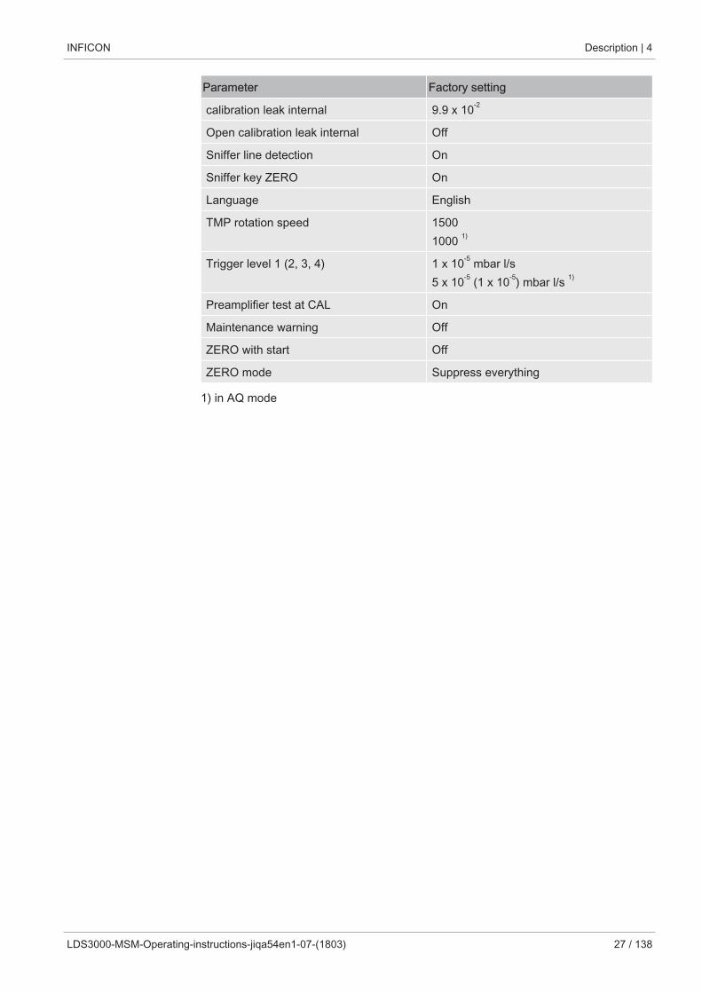
Parameter Factory setting
calibration leak internal 9.9 x 10⁻²
Open calibration leak internal Off
Sniffer line detection On
Sniffer key ZERO On
Language English
TMP rotation speed 15001000 1)
Trigger level 1 (2, 3, 4) 1 x 10⁻⁵ mbar l/s 5 x 10⁻⁵ (1 x 10⁻⁵) mbar l/s 1)
Preamplifier test at CAL On
Maintenance warning Off
ZERO with start Off
ZERO mode Suppress everything
1) in AQ mode
5 | Mounting LDS3000 INFICON
28 / 138 LDS3000-MSM-Operating-instructions-jiqa54en1-07-(1803)
5 Mounting LDS3000
5.1 Adjust the position of the connections to theinstallation dimensions
Select location
Select the most helium-free environment possible for the measurement setup. For reli-able measurements with the device, the helium content in the air must be less than 10ppm.
By nature, air contains 5 ppm (0.0005%) helium.
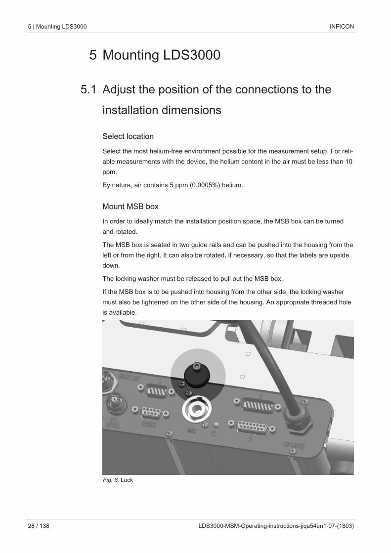
Mount MSB box
In order to ideally match the installation position space, the MSB box can be turnedand rotated.
The MSB box is seated in two guide rails and can be pushed into the housing from theleft or from the right. It can also be rotated, if necessary, so that the labels are upsidedown.
The locking washer must be released to pull out the MSB box.
If the MSB box is to be pushed into housing from the other side, the locking washermust also be tightened on the other side of the housing. An appropriate threaded holeis available.
Fig. 8: Lock
INFICON Mounting LDS3000 | 5
LDS3000-MSM-Operating-instructions-jiqa54en1-07-(1803) 29 / 138
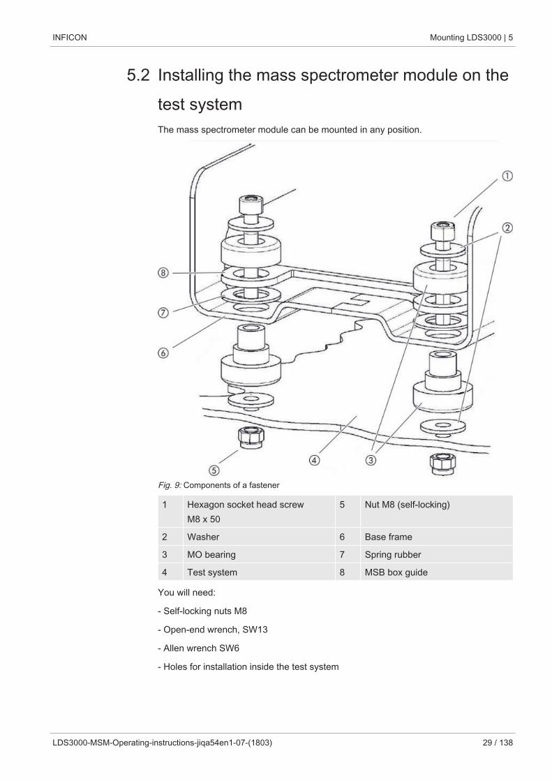
5.2 Installing the mass spectrometer module on thetest systemThe mass spectrometer module can be mounted in any position.
Fig. 9: Components of a fastener
1 Hexagon socket head screwM8 x 50
5 Nut M8 (self-locking)
2 Washer 6 Base frame
3 MO bearing 7 Spring rubber
4 Test system 8 MSB box guide
You will need:
- Self-locking nuts M8
- Open-end wrench, SW13
- Allen wrench SW6
- Holes for installation inside the test system
5 | Mounting LDS3000 INFICON
30 / 138 LDS3000-MSM-Operating-instructions-jiqa54en1-07-(1803)
In delivery condition, the bearings are attached to the base frame with the hexagonsocket screws and transport nuts. Use the supplied self-locking nuts for the installationof the mass spectrometer module – not the transport nuts.
The background must be stable.
WARNING
Severe injuries due to mass spectrometer module breaking out
If not screwed down properly, the mass spectrometer module can be caused to breakout if the rotor of the turbo molecular pump suddenly locks up. This can result in in-juries of the most severe kind.
► Make sure the mount of the mass spectrometer module is able to absorb a brakingtorque of 820 Nm.
1 Drill through-holes: – X distance: 283 mm – Y-distance: 121,5 mm – Through hole in sheet: Ø 9 mm – Fixing screws: M8 x 50
2 Remove transport nuts.
3 Place the mass spectrometer module on top of the through-holes and screw itdown using the fasteners as shown in the upper figure .
5.3 Select connection ULTRA, FINE, or GROSSThe operation mode of the vacuum connection and the rotation speed of the turbomolecular pump define:
• Minimum detectable leak rate (MDLR)
• Constantly permissible inlet pressure (pmax)
• Pumping speed (S)
The following information applies to the use of helium as a tracer gas.
To reach the MDLR, the following conditions must be met:
• The LDS3000 must be in operation for at least 20 minutes.
• Ambient conditions must be steady (temperature, no vibrations/shocks, clean envi-ronment)
INFICON Mounting LDS3000 | 5
LDS3000-MSM-Operating-instructions-jiqa54en1-07-(1803) 31 / 138
• The specimen must be operated with switched-off ZERO until to the background isstable. The ZERO function may be switched on only after that.
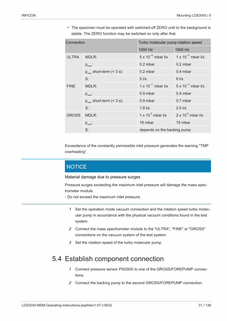
Connection Turbo molecular pump rotation speed
1000 Hz 1500 Hz
ULTRA MDLR: 5 x 10-12 mbar l/s 1 x 10-11 mbar l/s
pmax: 0.2 mbar 0.2 mbar
pmax short-term (< 3 s): 0.2 mbar 0.4 mbar
S: 5 l/s 6 l/s
FINE MDLR: 1 x 10-11 mbar l/s 5 x 10-11 mbar l/s
pmax: 0.9 mbar 0.4 mbar
pmax short-term (< 3 s): 0.9 mbar 0.7 mbar
S: 1.8 l/s 2.5 l/s
GROSS MDLR: 1 x 10⁻⁹ mbar l/s 2 x 10⁻⁸ mbar l/s
pmax: 18 mbar 15 mbar
S: depends on the backing pump
Exceedance of the constantly permissible inlet pressure generates the warning "TMPoverheating".
NOTICE
Material damage due to pressure surges
Pressure surges exceeding the maximum inlet pressure will damage the mass spec-trometer module.- Do not exceed the maximum inlet pressure.
1 Set the operation mode vacuum connection and the rotation speed turbo molec-ular pump in accordance with the physical vacuum conditions found in the testsystem.
2 Connect the mass spectrometer module to the "ULTRA", "FINE" or "GROSS"connections on the vacuum system of the test system.
3 Set the rotation speed of the turbo molecular pump.
5.4 Establish component connection1 Connect pressure sensor PSG500 to one of the GROSS/FOREPUMP connec-
tions.
2 Connect the backing pump to the second GROSS/FOREPUMP connection.
5 | Mounting LDS3000 INFICON
32 / 138 LDS3000-MSM-Operating-instructions-jiqa54en1-07-(1803)
3 For sniffer mode, connect the sniffer line to one of the FINE-/SNIFFER connec-tions.
4 If available, connect internal calibration leak 560-323 to the second free flange(FINE or ULTRA) of the vacuum connection.
When using a sniffer valve: For the device to operate correctly upon opening of thesniffer valve, no additional line can be connected between the connection block andthe sniffer valve or between the sniffer valve and the sniffer line.
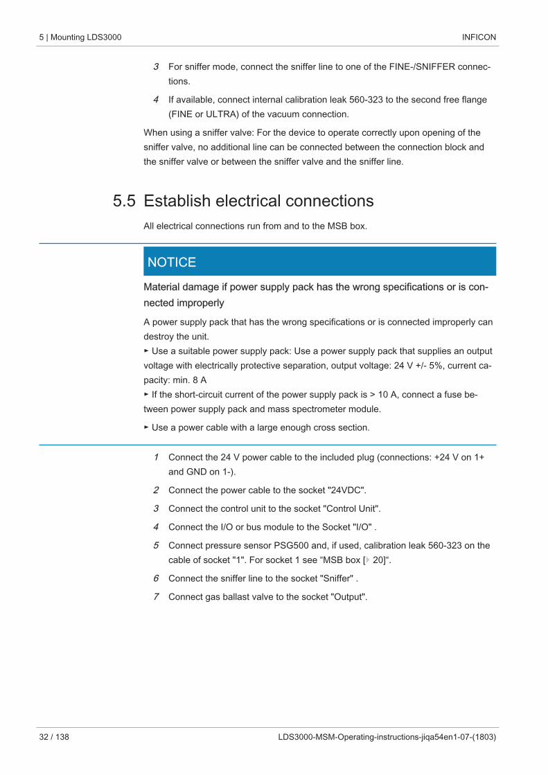
5.5 Establish electrical connectionsAll electrical connections run from and to the MSB box.
NOTICE
Material damage if power supply pack has the wrong specifications or is con-nected improperly
A power supply pack that has the wrong specifications or is connected improperly candestroy the unit.► Use a suitable power supply pack: Use a power supply pack that supplies an outputvoltage with electrically protective separation, output voltage: 24 V +/- 5%, current ca-pacity: min. 8 A► If the short-circuit current of the power supply pack is > 10 A, connect a fuse be-tween power supply pack and mass spectrometer module.
► Use a power cable with a large enough cross section.
1 Connect the 24 V power cable to the included plug (connections: +24 V on 1+and GND on 1-).
2 Connect the power cable to the socket "24VDC".
3 Connect the control unit to the socket "Control Unit".
4 Connect the I/O or bus module to the Socket "I/O" .
5 Connect pressure sensor PSG500 and, if used, calibration leak 560-323 on thecable of socket "1". For socket 1 see “MSB box [} 20]“.
6 Connect the sniffer line to the socket "Sniffer" .
7 Connect gas ballast valve to the socket "Output".
INFICON Mounting LDS3000 AQ (Accumulation) | 6
LDS3000-MSM-Operating-instructions-jiqa54en1-07-(1803) 33 / 138
6 Mounting LDS3000 AQ (Accumulation)
6.1 Adjust the position of the connections to theinstallation dimensions
Select location
Select the most helium-free environment possible for the measurement setup. For reli-able measurements with the device, the helium content in the air must be less than 10ppm.
By nature, air contains 5 ppm (0.0005%) helium.
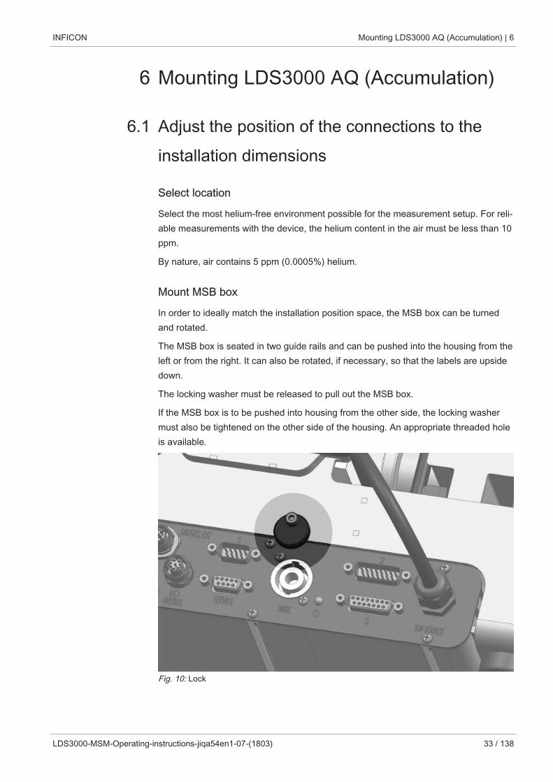
Mount MSB box
In order to ideally match the installation position space, the MSB box can be turnedand rotated.
The MSB box is seated in two guide rails and can be pushed into the housing from theleft or from the right. It can also be rotated, if necessary, so that the labels are upsidedown.
The locking washer must be released to pull out the MSB box.
If the MSB box is to be pushed into housing from the other side, the locking washermust also be tightened on the other side of the housing. An appropriate threaded holeis available.
Fig. 10: Lock
6 | Mounting LDS3000 AQ (Accumulation) INFICON
34 / 138 LDS3000-MSM-Operating-instructions-jiqa54en1-07-(1803)
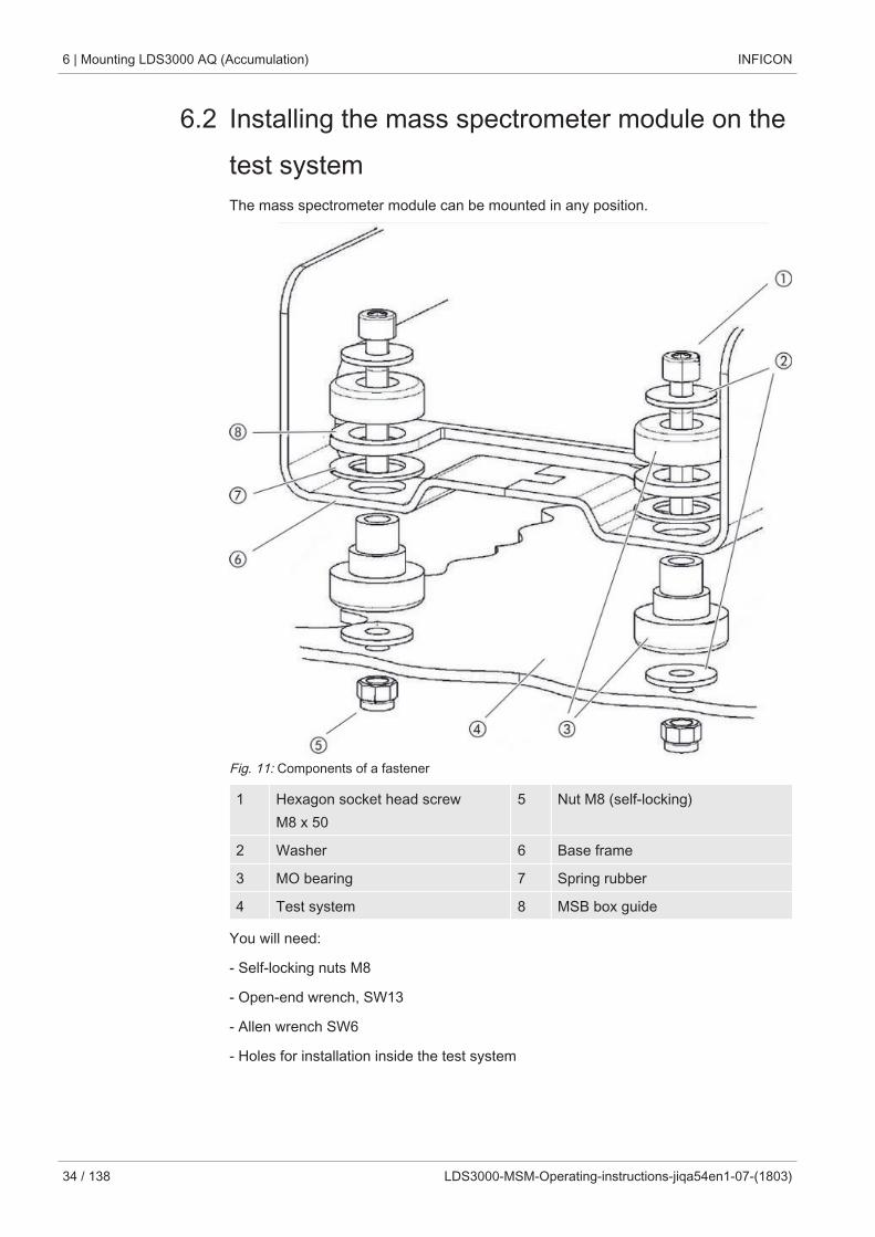
6.2 Installing the mass spectrometer module on thetest systemThe mass spectrometer module can be mounted in any position.
Fig. 11: Components of a fastener
1 Hexagon socket head screwM8 x 50
5 Nut M8 (self-locking)
2 Washer 6 Base frame
3 MO bearing 7 Spring rubber
4 Test system 8 MSB box guide
You will need:
- Self-locking nuts M8
- Open-end wrench, SW13
- Allen wrench SW6
- Holes for installation inside the test system

INFICON Mounting LDS3000 AQ (Accumulation) | 6
LDS3000-MSM-Operating-instructions-jiqa54en1-07-(1803) 35 / 138
In delivery condition, the bearings are attached to the base frame with the hexagonsocket screws and transport nuts. Use the supplied self-locking nuts for the installationof the mass spectrometer module – not the transport nuts.
The background must be stable.
WARNING
Severe injuries due to mass spectrometer module breaking out
If not screwed down properly, the mass spectrometer module can be caused to breakout if the rotor of the turbo molecular pump suddenly locks up. This can result in in-juries of the most severe kind.
► Make sure the mount of the mass spectrometer module is able to absorb a brakingtorque of 820 Nm.
1 Drill through-holes: – X distance: 283 mm – Y-distance: 121,5 mm – Through hole in sheet: Ø 9 mm – Fixing screws: M8 x 50
2 Remove transport nuts.
3 Place the mass spectrometer module on top of the through-holes and screw itdown using the fasteners as shown in the upper figure .
6 | Mounting LDS3000 AQ (Accumulation) INFICON
36 / 138 LDS3000-MSM-Operating-instructions-jiqa54en1-07-(1803)
6.3 Select components and connect
312 6 7
14
5
48
49
411
410
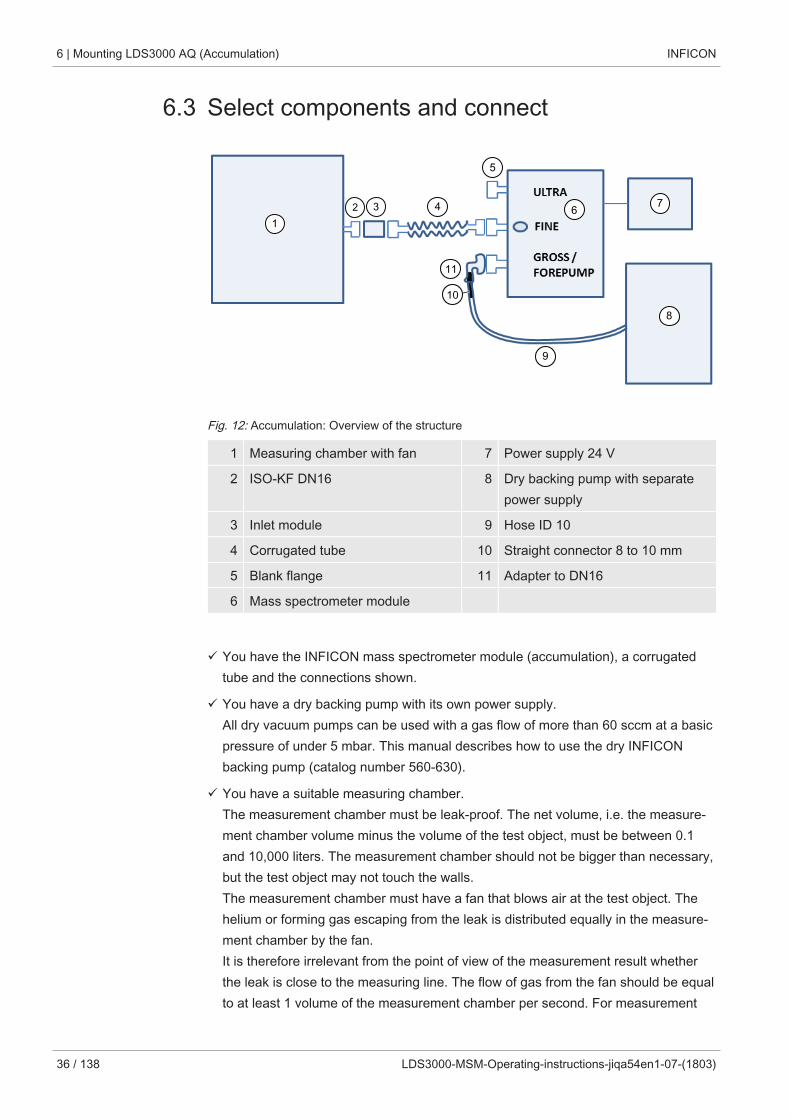
Fig. 12: Accumulation: Overview of the structure
1 Measuring chamber with fan 7 Power supply 24 V
2 ISO-KF DN16 8 Dry backing pump with separatepower supply
3 Inlet module 9 Hose ID 10
4 Corrugated tube 10 Straight connector 8 to 10 mm
5 Blank flange 11 Adapter to DN16
6 Mass spectrometer module
ü You have the INFICON mass spectrometer module (accumulation), a corrugatedtube and the connections shown.
ü You have a dry backing pump with its own power supply.All dry vacuum pumps can be used with a gas flow of more than 60 sccm at a basicpressure of under 5 mbar. This manual describes how to use the dry INFICONbacking pump (catalog number 560-630).
ü You have a suitable measuring chamber.The measurement chamber must be leak-proof. The net volume, i.e. the measure-ment chamber volume minus the volume of the test object, must be between 0.1and 10,000 liters. The measurement chamber should not be bigger than necessary,but the test object may not touch the walls.The measurement chamber must have a fan that blows air at the test object. Thehelium or forming gas escaping from the leak is distributed equally in the measure-ment chamber by the fan.It is therefore irrelevant from the point of view of the measurement result whetherthe leak is close to the measuring line. The flow of gas from the fan should be equalto at least 1 volume of the measurement chamber per second. For measurement
INFICON Mounting LDS3000 AQ (Accumulation) | 6
LDS3000-MSM-Operating-instructions-jiqa54en1-07-(1803) 37 / 138
times under 15 seconds, the flow of gas from the fan should be equal to at least 2volumes of the measurement chamber per second. A suitable measuring time iscalculated by the device.Note that a measuring chamber that is leak-proof but not vacuum-resistant can im-plode if it is pumped further out than usual measuring times. See also “Carrying outa measurement [} 82]“.
1 Connect the pressure sensor PSG500 to the FINE connector.
2 Connect a corrugated tube to the FINE port on the mass spectrometer module.
3 Connect the open end of the corrugated tube to the measuring chamber via theinlet module.
4 Fit an adapter to DN16 with throttle on the connection GROSS / FOREPUMP ofthe mass spectrometer module.
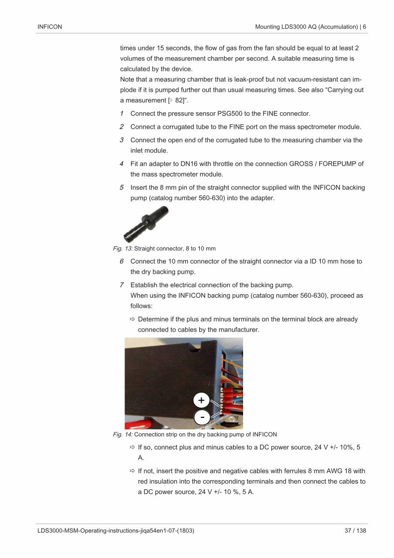
5 Insert the 8 mm pin of the straight connector supplied with the INFICON backingpump (catalog number 560-630) into the adapter.
Fig. 13: Straight connector, 8 to 10 mm
6 Connect the 10 mm connector of the straight connector via a ID 10 mm hose tothe dry backing pump.
7 Establish the electrical connection of the backing pump.When using the INFICON backing pump (catalog number 560-630), proceed asfollows:
ð Determine if the plus and minus terminals on the terminal block are alreadyconnected to cables by the manufacturer.
-+
Fig. 14: Connection strip on the dry backing pump of INFICON
ð If so, connect plus and minus cables to a DC power source, 24 V +/- 10%, 5A.
ð If not, insert the positive and negative cables with ferrules 8 mm AWG 18 withred insulation into the corresponding terminals and then connect the cables toa DC power source, 24 V +/- 10 %, 5 A.
6 | Mounting LDS3000 AQ (Accumulation) INFICON
38 / 138 LDS3000-MSM-Operating-instructions-jiqa54en1-07-(1803)
The backing pump exhaust air opening should be as far as possible from the testchamber.
See also
2 Entire device (LDS3000 AQ) [} 16]
6.4 Establish electrical connectionsAll electrical connections run from and to the MSB box.
NOTICE
Material damage if power supply pack has the wrong specifications or is con-nected improperly
A power supply pack that has the wrong specifications or is connected improperly candestroy the unit.► Use a suitable power supply pack: Use a power supply pack that supplies an outputvoltage with electrically protective separation, output voltage: 24 V +/- 5%, current ca-pacity: min. 8 A► If the short-circuit current of the power supply pack is > 10 A, connect a fuse be-tween power supply pack and mass spectrometer module.
► Use a power cable with a large enough cross section.
1 Mount the 24 V power supply cable to the enclosed plug (connections: +24 V on1+ and GND on 1-).
2 Connect the power supply cable to the "24VDC" socket.
3 Connect the operating unit to the "Control Unit" socket.
4 Connect the I/O or bus module to the "I/O" socket.
5 Connect the pressure sensor PSG500 to the cable of socket 1. For socket 1 see“MSB box [} 20]“.
INFICON Operation LDS3000 | 7
LDS3000-MSM-Operating-instructions-jiqa54en1-07-(1803) 39 / 138
7 Operation LDS3000You can use the following accessories in combination with the mass spectrometermodule:
• Control unit CU1000
• Bus module BM1000
• I/O module IO1000
With the available accessories XL sniffer adapter and sniffer line SL3000XL, it is pos-sible to capture leaks at a larger distance from the expected leak if the detection limitis deteriorated (operation in "high flow" mode).LDS3000 AQ devices can also be used if they are not operated in AQ mode.
Additional information on the control unit, the modules and the XL sniffer adapter is in-cluded in the documents:
• Operating Manual Control Unit CU1000
• Operating instructions I/O module IO1000
• Operating instructions bus module BM1000
• Operating instructions XL sniffer adapter
• Interface protocols LDS3000
The paths listed in the following sections refer to the operation of the mass spectrome-ter module with the control unit CU1000. If the bus module or the I/O module is used,the actions must be implemented within the scope of the protocol that is used.
The path information for the control unit always starts in the main menu.
WARNING
Danger to life and material damage due to unsuitable operating conditions
There is danger to life due to unsuitable operating conditions. The device can becomedamaged.
► Avoid changing the position of the device in an abrupt manner.
► Avoid extreme external vibrations and impact.
7.1 Switching the device on1 Switch on the backing pump.
2 Establish the power supply to the mass spectrometer module.
ð System starts up automatically.
7 | Operation LDS3000 INFICON
40 / 138 LDS3000-MSM-Operating-instructions-jiqa54en1-07-(1803)
ð If an XL Sniffer Adapter and the CU1000 are connected, your will be asked afterrun-up, whether the "XL Sniffer Adapter" operation mode should be set. Thisdoes not apply to devices in AQ mode.
Longer run-up time for devices in AQ mode
To counteract falsification of the measurement results by an increased backgroundvalue, the warm-up time after switching on is about 10 minutes.
Wait at least 60 minutes before determining the peak or before calibrating.
See also “Carrying out a measurement [} 82]“.
7.2 Default settingsLanguage selection Select the display language. The factory setting is English. (The display on the han-
dle of the SL3000XL sniffer line shows messages in English instead of in Russianand Chinese.)
GermanEnglishFrenchItalianSpanishPortugueseRussianChineseJapanese
Control unit Settings > Set up > Control unit > Language
LD protocol Command 398
ASCII protocol *CONFig:LANG
Setting date and time Setting the date
Format: DD.MM.YY
Control unit Settings > Date/Time > Date
LD protocol Command 450
ASCII protocol *HOUR:DATE
Setting the time
Format: hh: mm
Control unit Settings > Date/Time > Time
INFICON Operation LDS3000 | 7
LDS3000-MSM-Operating-instructions-jiqa54en1-07-(1803) 41 / 138
LD protocol Command 450
ASCII protocol *HOUR:TIME
7 | Operation LDS3000 INFICON
42 / 138 LDS3000-MSM-Operating-instructions-jiqa54en1-07-(1803)
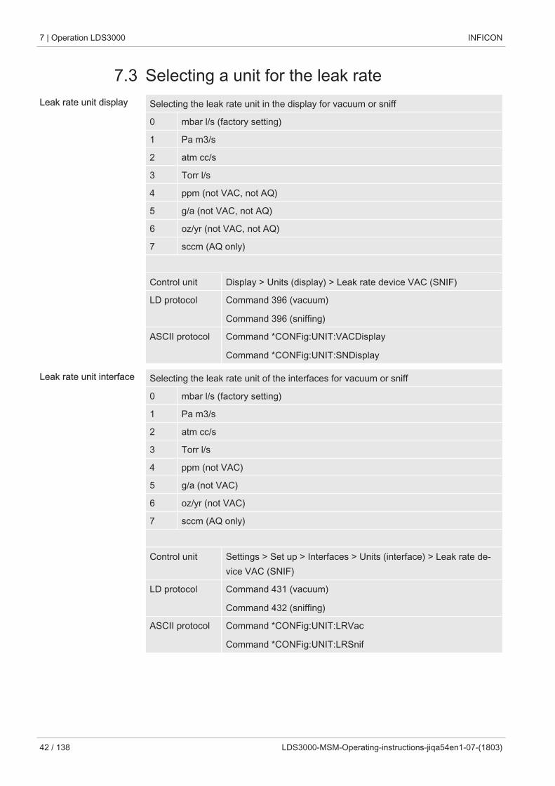
7.3 Selecting a unit for the leak rateLeak rate unit display Selecting the leak rate unit in the display for vacuum or sniff
0 mbar l/s (factory setting)
1 Pa m3/s
2 atm cc/s
3 Torr l/s
4 ppm (not VAC, not AQ)
5 g/a (not VAC, not AQ)
6 oz/yr (not VAC, not AQ)
7 sccm (AQ only)
Control unit Display > Units (display) > Leak rate device VAC (SNIF)
LD protocol Command 396 (vacuum)
Command 396 (sniffing)
ASCII protocol Command *CONFig:UNIT:VACDisplay
Command *CONFig:UNIT:SNDisplay
Leak rate unit interface Selecting the leak rate unit of the interfaces for vacuum or sniff
0 mbar l/s (factory setting)
1 Pa m3/s
2 atm cc/s
3 Torr l/s
4 ppm (not VAC)
5 g/a (not VAC)
6 oz/yr (not VAC)
7 sccm (AQ only)
Control unit Settings > Set up > Interfaces > Units (interface) > Leak rate de-vice VAC (SNIF)
LD protocol Command 431 (vacuum)
Command 432 (sniffing)
ASCII protocol Command *CONFig:UNIT:LRVac
Command *CONFig:UNIT:LRSnif
INFICON Operation LDS3000 | 7
LDS3000-MSM-Operating-instructions-jiqa54en1-07-(1803) 43 / 138
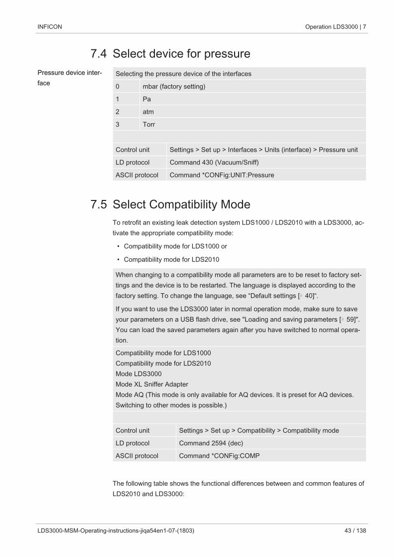
7.4 Select device for pressurePressure device inter-face
Selecting the pressure device of the interfaces
0 mbar (factory setting)
1 Pa
2 atm
3 Torr
Control unit Settings > Set up > Interfaces > Units (interface) > Pressure unit
LD protocol Command 430 (Vacuum/Sniff)
ASCII protocol Command *CONFig:UNIT:Pressure
7.5 Select Compatibility ModeTo retrofit an existing leak detection system LDS1000 / LDS2010 with a LDS3000, ac-tivate the appropriate compatibility mode:
• Compatibility mode for LDS1000 or
• Compatibility mode for LDS2010
When changing to a compatibility mode all parameters are to be reset to factory set-tings and the device is to be restarted. The language is displayed according to thefactory setting. To change the language, see “Default settings [} 40]“.
If you want to use the LDS3000 later in normal operation mode, make sure to saveyour parameters on a USB flash drive, see "Loading and saving parameters [} 59]".You can load the saved parameters again after you have switched to normal opera-tion.
Compatibility mode for LDS1000Compatibility mode for LDS2010Mode LDS3000Mode XL Sniffer AdapterMode AQ (This mode is only available for AQ devices. It is preset for AQ devices.Switching to other modes is possible.)
Control unit Settings > Set up > Compatibility > Compatibility mode
LD protocol Command 2594 (dec)
ASCII protocol Command *CONFig:COMP
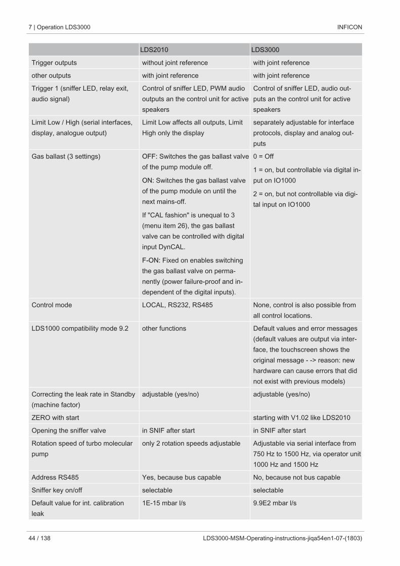
The following table shows the functional differences between and common features ofLDS2010 and LDS3000:
7 | Operation LDS3000 INFICON
44 / 138 LDS3000-MSM-Operating-instructions-jiqa54en1-07-(1803)
LDS2010 LDS3000
Trigger outputs without joint reference with joint reference
other outputs with joint reference with joint reference
Trigger 1 (sniffer LED, relay exit,audio signal)
Control of sniffer LED, PWM audiooutputs an the control unit for activespeakers
Control of sniffer LED, audio out-puts an the control unit for activespeakers
Limit Low / High (serial interfaces,display, analogue output)
Limit Low affects all outputs, LimitHigh only the display
separately adjustable for interfaceprotocols, display and analog out-puts
Gas ballast (3 settings) OFF: Switches the gas ballast valveof the pump module off.
ON: Switches the gas ballast valveof the pump module on until thenext mains-off.
If "CAL fashion" is unequal to 3(menu item 26), the gas ballastvalve can be controlled with digitalinput DynCAL.
F-ON: Fixed on enables switchingthe gas ballast valve on perma-nently (power failure-proof and in-dependent of the digital inputs).
0 = Off
1 = on, but controllable via digital in-put on IO1000
2 = on, but not controllable via digi-tal input on IO1000
Control mode LOCAL, RS232, RS485 None, control is also possible fromall control locations.
LDS1000 compatibility mode 9.2 other functions Default values and error messages(default values are output via inter-face, the touchscreen shows theoriginal message - -> reason: newhardware can cause errors that didnot exist with previous models)
Correcting the leak rate in Standby(machine factor)
adjustable (yes/no) adjustable (yes/no)
ZERO with start starting with V1.02 like LDS2010
Opening the sniffer valve in SNIF after start in SNIF after start
Rotation speed of turbo molecularpump
only 2 rotation speeds adjustable Adjustable via serial interface from750 Hz to 1500 Hz, via operator unit1000 Hz and 1500 Hz
Address RS485 Yes, because bus capable No, because not bus capable
Sniffer key on/off selectable selectable
Default value for int. calibrationleak
1E-15 mbar l/s 9.9E2 mbar l/s
INFICON Operation LDS3000 | 7
LDS3000-MSM-Operating-instructions-jiqa54en1-07-(1803) 45 / 138
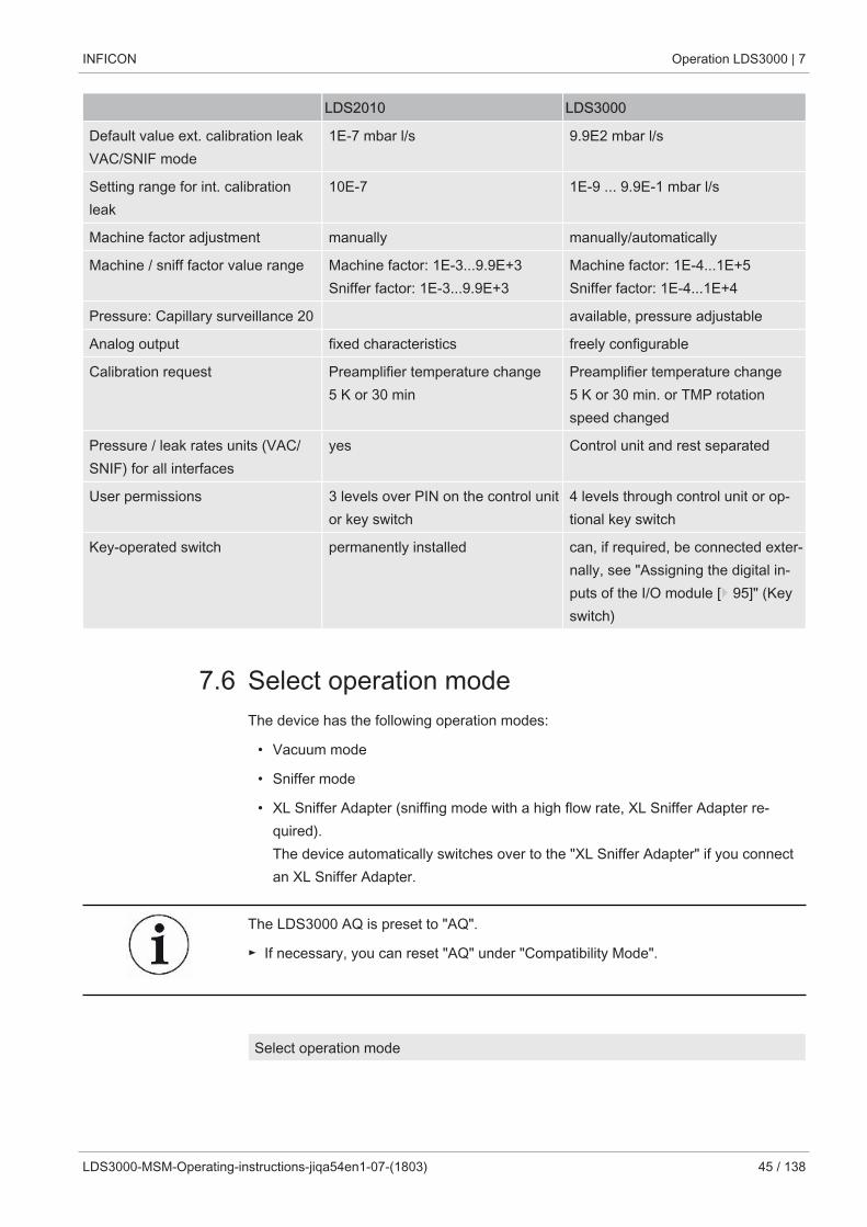
LDS2010 LDS3000
Default value ext. calibration leakVAC/SNIF mode
1E-7 mbar l/s 9.9E2 mbar l/s
Setting range for int. calibrationleak
10E-7 1E-9 ... 9.9E-1 mbar l/s
Machine factor adjustment manually manually/automatically
Machine / sniff factor value range Machine factor: 1E-3...9.9E+3Sniffer factor: 1E-3...9.9E+3
Machine factor: 1E-4...1E+5Sniffer factor: 1E-4...1E+4
Pressure: Capillary surveillance 20 available, pressure adjustable
Analog output fixed characteristics freely configurable
Calibration request Preamplifier temperature change5 K or 30 min
Preamplifier temperature change5 K or 30 min. or TMP rotationspeed changed
Pressure / leak rates units (VAC/SNIF) for all interfaces
yes Control unit and rest separated
User permissions 3 levels over PIN on the control unitor key switch
4 levels through control unit or op-tional key switch
Key-operated switch permanently installed can, if required, be connected exter-nally, see "Assigning the digital in-puts of the I/O module [} 95]" (Keyswitch)
7.6 Select operation modeThe device has the following operation modes:
• Vacuum mode
• Sniffer mode
• XL Sniffer Adapter (sniffing mode with a high flow rate, XL Sniffer Adapter re-quired).The device automatically switches over to the "XL Sniffer Adapter" if you connectan XL Sniffer Adapter.
The LDS3000 AQ is preset to "AQ".
► If necessary, you can reset "AQ" under "Compatibility Mode".
Select operation mode
7 | Operation LDS3000 INFICON
46 / 138 LDS3000-MSM-Operating-instructions-jiqa54en1-07-(1803)
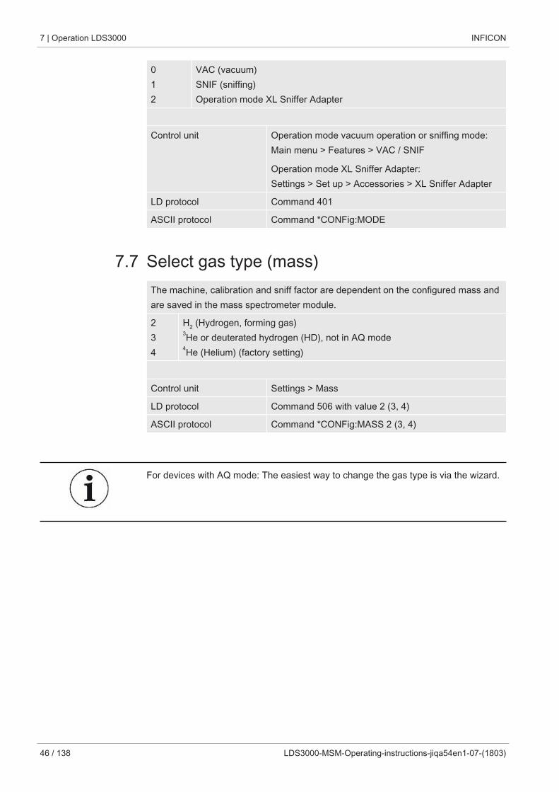
0 1 2
VAC (vacuum)SNIF (sniffing) Operation mode XL Sniffer Adapter
Control unit Operation mode vacuum operation or sniffing mode:Main menu > Features > VAC / SNIF
Operation mode XL Sniffer Adapter:Settings > Set up > Accessories > XL Sniffer Adapter
LD protocol Command 401
ASCII protocol Command *CONFig:MODE
7.7 Select gas type (mass)The machine, calibration and sniff factor are dependent on the configured mass andare saved in the mass spectrometer module.
2 3 4
H2 (Hydrogen, forming gas)3He or deuterated hydrogen (HD), not in AQ mode4He (Helium) (factory setting)
Control unit Settings > Mass
LD protocol Command 506 with value 2 (3, 4)
ASCII protocol Command *CONFig:MASS 2 (3, 4)
For devices with AQ mode: The easiest way to change the gas type is via the wizard.
INFICON Operation LDS3000 | 7
LDS3000-MSM-Operating-instructions-jiqa54en1-07-(1803) 47 / 138
7.8 Calibrating the device
7.8.1 Time and general preferences
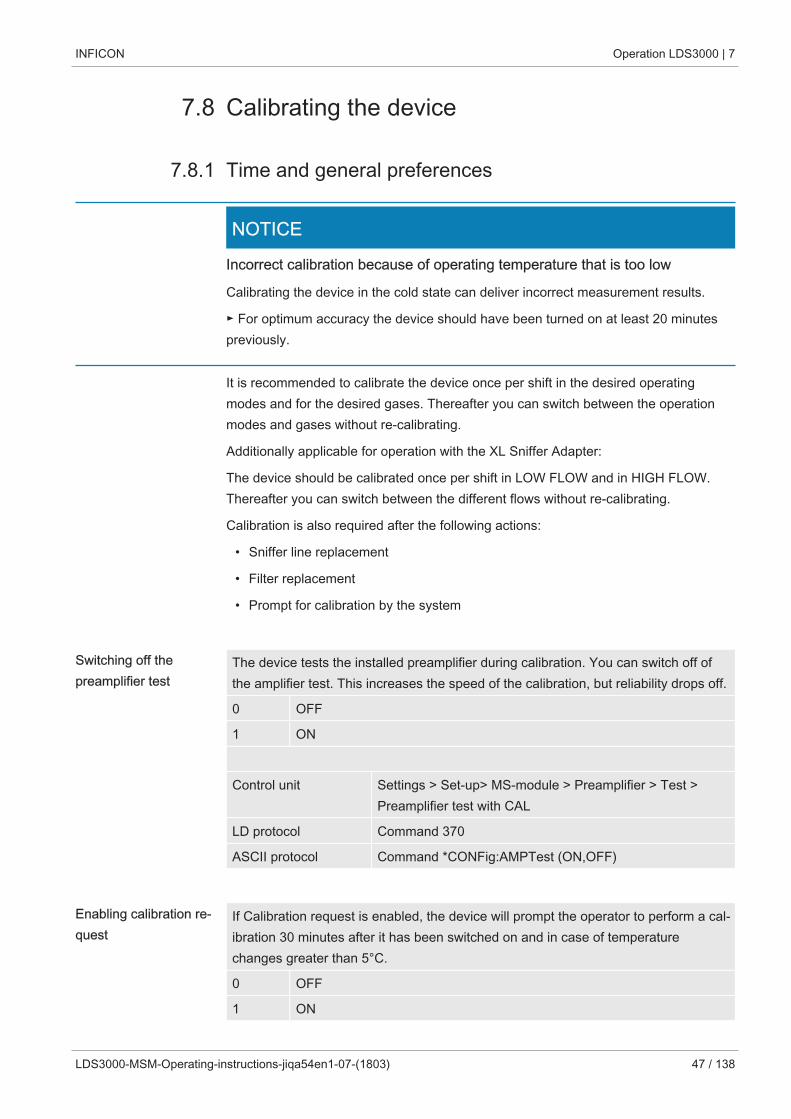
NOTICE
Incorrect calibration because of operating temperature that is too low
Calibrating the device in the cold state can deliver incorrect measurement results.
► For optimum accuracy the device should have been turned on at least 20 minutespreviously.
It is recommended to calibrate the device once per shift in the desired operatingmodes and for the desired gases. Thereafter you can switch between the operationmodes and gases without re-calibrating.
Additionally applicable for operation with the XL Sniffer Adapter:
The device should be calibrated once per shift in LOW FLOW and in HIGH FLOW.Thereafter you can switch between the different flows without re-calibrating.
Calibration is also required after the following actions:
• Sniffer line replacement
• Filter replacement
• Prompt for calibration by the system
Switching off thepreamplifier test
The device tests the installed preamplifier during calibration. You can switch off ofthe amplifier test. This increases the speed of the calibration, but reliability drops off.
0 OFF
1 ON
Control unit Settings > Set-up> MS-module > Preamplifier > Test >Preamplifier test with CAL
LD protocol Command 370
ASCII protocol Command *CONFig:AMPTest (ON,OFF)
Enabling calibration re-quest
If Calibration request is enabled, the device will prompt the operator to perform a cal-ibration 30 minutes after it has been switched on and in case of temperaturechanges greater than 5°C.
0 OFF
1 ON
7 | Operation LDS3000 INFICON
48 / 138 LDS3000-MSM-Operating-instructions-jiqa54en1-07-(1803)
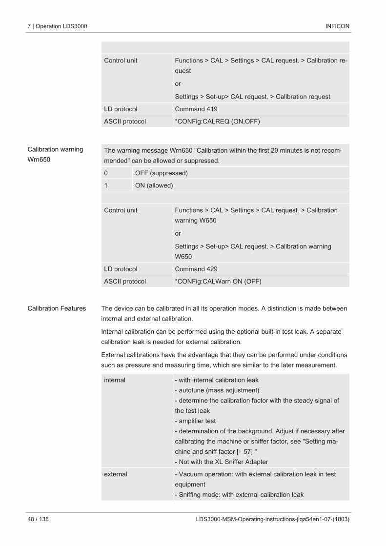
Control unit Functions > CAL > Settings > CAL request. > Calibration re-quest
or
Settings > Set-up> CAL request. > Calibration request
LD protocol Command 419
ASCII protocol *CONFig:CALREQ (ON,OFF)
Calibration warningWrn650
The warning message Wrn650 "Calibration within the first 20 minutes is not recom-mended" can be allowed or suppressed.
0 OFF (suppressed)
1 ON (allowed)
Control unit Functions > CAL > Settings > CAL request. > Calibrationwarning W650
or
Settings > Set-up> CAL request. > Calibration warningW650
LD protocol Command 429
ASCII protocol *CONFig:CALWarn ON (OFF)
Calibration Features The device can be calibrated in all its operation modes. A distinction is made betweeninternal and external calibration.
Internal calibration can be performed using the optional built-in test leak. A separatecalibration leak is needed for external calibration.
External calibrations have the advantage that they can be performed under conditionssuch as pressure and measuring time, which are similar to the later measurement.
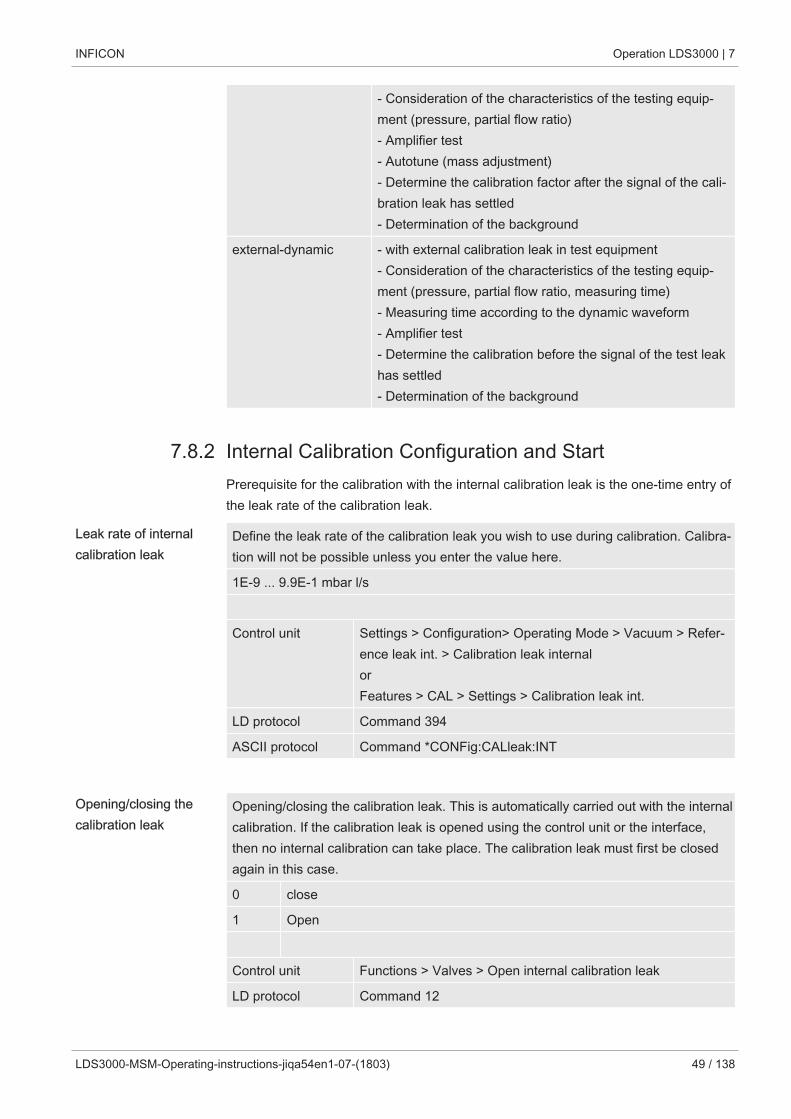
internal - with internal calibration leak- autotune (mass adjustment)- determine the calibration factor with the steady signal ofthe test leak- amplifier test- determination of the background. Adjust if necessary aftercalibrating the machine or sniffer factor, see "Setting ma-chine and sniff factor [} 57] "- Not with the XL Sniffer Adapter
external - Vacuum operation: with external calibration leak in testequipment- Sniffing mode: with external calibration leak
INFICON Operation LDS3000 | 7
LDS3000-MSM-Operating-instructions-jiqa54en1-07-(1803) 49 / 138
- Consideration of the characteristics of the testing equip-ment (pressure, partial flow ratio)- Amplifier test - Autotune (mass adjustment)- Determine the calibration factor after the signal of the cali-bration leak has settled- Determination of the background
external-dynamic - with external calibration leak in test equipment- Consideration of the characteristics of the testing equip-ment (pressure, partial flow ratio, measuring time)- Measuring time according to the dynamic waveform- Amplifier test- Determine the calibration before the signal of the test leakhas settled- Determination of the background
7.8.2 Internal Calibration Configuration and StartPrerequisite for the calibration with the internal calibration leak is the one-time entry ofthe leak rate of the calibration leak.
Leak rate of internalcalibration leak
Define the leak rate of the calibration leak you wish to use during calibration. Calibra-tion will not be possible unless you enter the value here.
1E-9 ... 9.9E-1 mbar l/s
Control unit Settings > Configuration> Operating Mode > Vacuum > Refer-ence leak int. > Calibration leak internalorFeatures > CAL > Settings > Calibration leak int.
LD protocol Command 394
ASCII protocol Command *CONFig:CALleak:INT
Opening/closing thecalibration leak
Opening/closing the calibration leak. This is automatically carried out with the internalcalibration. If the calibration leak is opened using the control unit or the interface,then no internal calibration can take place. The calibration leak must first be closedagain in this case.
0 close
1 Open
Control unit Functions > Valves > Open internal calibration leak
LD protocol Command 12
7 | Operation LDS3000 INFICON
50 / 138 LDS3000-MSM-Operating-instructions-jiqa54en1-07-(1803)
ASCII protocol Command *STATus:VALVE:TestLeak (ON, OFF)
► Start calibrationOperating unit: Features > CAL > InternLD protocol: 4, Parameter 0ASCII protocol: *CAL:INTIO1000: CAL internal, see "Settings for I/O module IO1000 [} 87]"
ð Calibration is performed automatically.
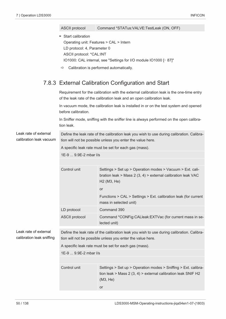
7.8.3 External Calibration Configuration and StartRequirement for the calibration with the external calibration leak is the one-time entryof the leak rate of the calibration leak and an open calibration leak.
In vacuum mode, the calibration leak is installed in or on the test system and openedbefore calibration.
In Sniffer mode, sniffing with the sniffer line is always performed on the open calibra-tion leak.
Leak rate of externalcalibration leak vacuum
Define the leak rate of the calibration leak you wish to use during calibration. Calibra-tion will not be possible unless you enter the value here.
A specific leak rate must be set for each gas (mass).
1E-9 ... 9.9E-2 mbar l/s
Control unit Settings > Set up > Operation modes > Vacuum > Ext. cali-bration leak > Mass 2 (3, 4) > external calibration leak VACH2 (M3, He)
or
Functions > CAL > Settings > Ext. calibration leak (for currentmass in selected unit)
LD protocol Command 390
ASCII protocol Command *CONFig:CALleak:EXTVac (for current mass in se-lected unit)
Leak rate of externalcalibration leak sniffing
Define the leak rate of the calibration leak you wish to use during calibration. Calibra-tion will not be possible unless you enter the value here.
A specific leak rate must be set for each gas (mass).
1E-9 ... 9.9E-2 mbar l/s
Control unit Settings > Set up > Operation modes > Sniffing > Ext. calibra-tion leak > Mass 2 (3, 4) > external calibration leak SNIF H2(M3, He)
or
INFICON Operation LDS3000 | 7
LDS3000-MSM-Operating-instructions-jiqa54en1-07-(1803) 51 / 138
Functions > CAL > Settings > Ext. calibration leak (for currentmass in selected unit)
LD protocol Command 392
ASCII protocol Command *CONFig:CALleak:EXTSniff (for current mass indevice selected unit)
► LD and ASCII protocol: The status must be queried via: Command 260 or *STA-Tus:CAL
1 Open external calibration leak or hold sniffer line to calibration leak.
2 Start measurement.
3 Wait until leak rate signal is tuned and stable.
4 Start calibration:Control unit: Features > CAL > ExternLD protocol: 4, Parameter 1ASCII protocol: *CAL:EXTIO1000: see the figure below.
ð Request to "close calibration leak"
5 Vacuum mode: Close calibration leak inside the test system.Sniffer mode: Remove sniffer line from calibration leak.
ð Leak rate signal decreases.
6 Confirm measured background value is stable:Control unit: "OK"LD protocol: 11, Parameter 1ASCII protocol: *CAL:CLOSEDIO1000 see the figure below.
ð Calibration is completed if:Control unit: Old and new calibration factor are displayedLD protocol LD instruction 260 provides 0 (READY)ASCII protocol: Command *STATus:CAL? provides IDLEIO1000 see the figure below.
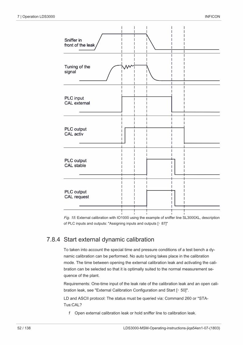
7 | Operation LDS3000 INFICON
52 / 138 LDS3000-MSM-Operating-instructions-jiqa54en1-07-(1803)
Fig. 15: External calibration with IO1000 using the example of sniffer line SL3000XL, descriptionof PLC inputs and outputs: "Assigning inputs and outputs [} 87]"
7.8.4 Start external dynamic calibrationTo taken into account the special time and pressure conditions of a test bench a dy-namic calibration can be performed. No auto tuning takes place in the calibrationmode. The time between opening the external calibration leak and activating the cali-bration can be selected so that it is optimally suited to the normal measurement se-quence of the plant.
Requirements: One-time input of the leak rate of the calibration leak and an open cali-bration leak, see "External Calibration Configuration and Start [} 50]".
LD and ASCII protocol: The status must be queried via: Command 260 or *STA-Tus:CAL?
1 Open external calibration leak or hold sniffer line to calibration leak.
INFICON Operation LDS3000 | 7
LDS3000-MSM-Operating-instructions-jiqa54en1-07-(1803) 53 / 138
2 Start measurement.
3 Wait until the leak rate signal is optimally suited to the normal measurement se-quence of the plant.
4 Start calibration:Control unit: Features > CAL > DynamicLD protocol: 4, Parameter 2ASCII protocol: *CAL:DYNIO1000 see the figure below.
ð Request to "close calibration leak"
5 Vacuum mode: Close calibration leak inside the test system.Sniffer mode: Remove sniffer line from calibration leak.
ð Leak rate signal decreases.
6 Confirm measured background value:Control unit: "OK"LD protocol: 11, Parameter 1ASCII protocol: *CAL:CLOSEDIO1000 see the figure below.
ð Calibration is completed if:Control unit: Old and new calibration factor are displayedLD protocol LD instruction 260 provides 0 (READY)ASCII protocol: Command *STATus:CAL? provides IDLEIO1000 see the figure below.
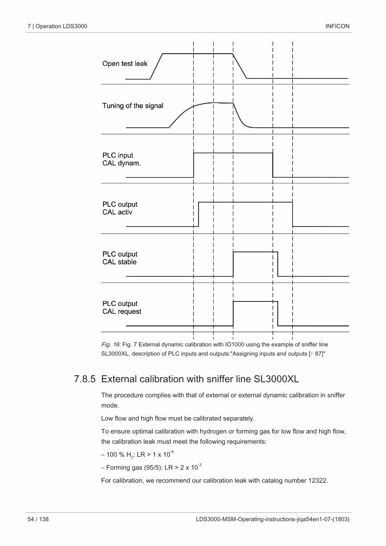
7 | Operation LDS3000 INFICON
54 / 138 LDS3000-MSM-Operating-instructions-jiqa54en1-07-(1803)
Fig. 16: Fig. 7 External dynamic calibration with IO1000 using the example of sniffer lineSL3000XL, description of PLC inputs and outputs:"Assigning inputs and outputs [} 87]"
7.8.5 External calibration with sniffer line SL3000XLThe procedure complies with that of external or external dynamic calibration in sniffermode.
Low flow and high flow must be calibrated separately.
To ensure optimal calibration with hydrogen or forming gas for low flow and high flow,the calibration leak must meet the following requirements:
– 100 % H2: LR > 1 x 10⁻⁴
– Forming gas (95/5): LR > 2 x 10⁻³
For calibration, we recommend our calibration leak with catalog number 12322.
INFICON Operation LDS3000 | 7
LDS3000-MSM-Operating-instructions-jiqa54en1-07-(1803) 55 / 138
7.8.6 Check the calibrationTo check whether a re-calibration is necessary, check the already existing.
7.8.6.1 Calibration using the internal calibration leak testThe test is only possible with the setting "Mass 4".
► Start test:Control unit: Features > CAL > Test int.LD protocol: 4, Parameter 4ASCII protocol: *CAL:PROOFINTIO1000: CAL test internal, see "Settings for I/O module IO1000 [} 87]"
ð Test is performed automatically.
7.8.6.2 Calibration using the external calibration leak test► LD and ASCII protocol: The status must be queried via: Command 260 or *STA-Tus:CAL
1 Open external calibration leak or hold sniffer line to calibration leak.
2 Wait until leak rate signal is tuned and stable.
3 Start test:Control unit: Functions > CAL > Test ext.LD protocol: 4, Parameter 5ASCII protocol: *CAL:PROOFEXTIO1000 compare figure in "External Calibration Configuration and Start [} 50]".
ð Request to "close calibration leak"
4 Vacuum mode: Close calibration leak inside the test system.Sniffer mode: Remove sniffer line from calibration leak.
ð Leak rate signal decreases.
5 Confirm measured background value is stable:Control unit: "OK"LD protocol: 11, Parameter 1ASCII protocol: *CAL:CLOSEDIO1000 compare figure in "External Calibration Configuration and Start [} 50]".
ð Test is completed if:Control unit: Result is displayedLD protocol: As with the other steps, the status must be queriedASCII protocol: As with the other steps, the status must be queriedIO1000 compare figure in "External Calibration Configuration and Start [} 50]".
7 | Operation LDS3000 INFICON
56 / 138 LDS3000-MSM-Operating-instructions-jiqa54en1-07-(1803)
7.8.7 Entering the calibration factorThe calibration is usually determined by the appropriate calibration routine. Therefore,it is usually not necessary to adjust the calibration factor manually.
An incorrectly set calibration inevitably leads to wrong leak rate indicator!
7.8.7.1 Calibration factor sniffing
Entry of the calibration factors for masses 2, 3, 4 in low flow and in high flow.
The values will be overwritten during the next calibration.
"High Flow-" or XL settings are available only in operation mode "XL SnifferAdapter".
The calibration factor for low flow also applies to sniffer applications that are not car-ried out in the operation mode "XL sniffer adapter".
The calibration factors are managed separately to earth and to "High Flow" and "LowFlow".
0.01 … 100
Control unit Settings > Set up > Operation modes > Sniffing > Calibr. factor >mass 2 (3, 4, 2 XL, 3 XL, 4 XL) >calibration factor SNIF H2 (M3,He, XL H2, XL M3, XL He)
LD protocol Commands 519, 521
ASCII protocol Command *FACtor:CALSniff or *FACtor:CALSXL for the currentmass
7.8.7.2 Calibration factor vacuumAlso applies to devices in AQ mode.
Entry of calibration factors for masses 2, 3, 4.
The values will be overwritten during the next calibration.
0.01 … 5000
Control unit Settings > Set up > Operation modes > Vacuum > Calibr. factor> mass 2 (3, 4) > calibration factor VAC H2 (M3, He)
LD protocol Command 520
ASCII protocol Command *FACtor:CALVac
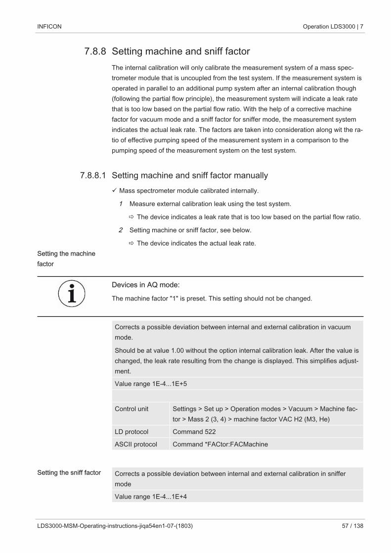
INFICON Operation LDS3000 | 7
LDS3000-MSM-Operating-instructions-jiqa54en1-07-(1803) 57 / 138
7.8.8 Setting machine and sniff factorThe internal calibration will only calibrate the measurement system of a mass spec-trometer module that is uncoupled from the test system. If the measurement system isoperated in parallel to an additional pump system after an internal calibration though(following the partial flow principle), the measurement system will indicate a leak ratethat is too low based on the partial flow ratio. With the help of a corrective machinefactor for vacuum mode and a sniff factor for sniffer mode, the measurement systemindicates the actual leak rate. The factors are taken into consideration along wit the ra-tio of effective pumping speed of the measurement system in a comparison to thepumping speed of the measurement system on the test system.
7.8.8.1 Setting machine and sniff factor manuallyü Mass spectrometer module calibrated internally.
1 Measure external calibration leak using the test system.
ð The device indicates a leak rate that is too low based on the partial flow ratio.
2 Setting machine or sniff factor, see below.
ð The device indicates the actual leak rate.Setting the machinefactor
Devices in AQ mode:
The machine factor "1" is preset. This setting should not be changed.
Corrects a possible deviation between internal and external calibration in vacuummode.
Should be at value 1.00 without the option internal calibration leak. After the value ischanged, the leak rate resulting from the change is displayed. This simplifies adjust-ment.
Value range 1E-4...1E+5
Control unit Settings > Set up > Operation modes > Vacuum > Machine fac-tor > Mass 2 (3, 4) > machine factor VAC H2 (M3, He)
LD protocol Command 522
ASCII protocol Command *FACtor:FACMachine
Setting the sniff factor Corrects a possible deviation between internal and external calibration in sniffermode
Value range 1E-4...1E+4
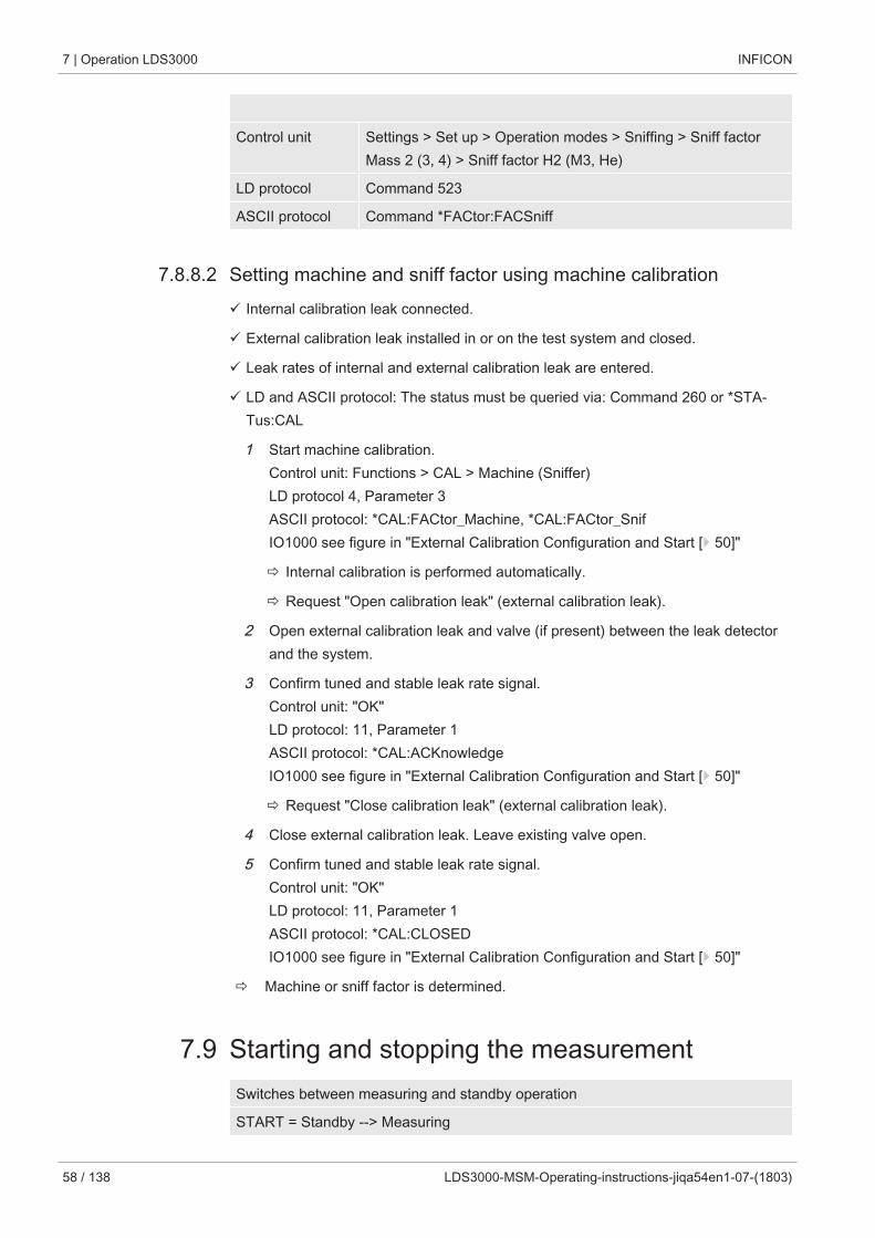
7 | Operation LDS3000 INFICON
58 / 138 LDS3000-MSM-Operating-instructions-jiqa54en1-07-(1803)
Control unit Settings > Set up > Operation modes > Sniffing > Sniff factorMass 2 (3, 4) > Sniff factor H2 (M3, He)
LD protocol Command 523
ASCII protocol Command *FACtor:FACSniff
7.8.8.2 Setting machine and sniff factor using machine calibrationü Internal calibration leak connected.
ü External calibration leak installed in or on the test system and closed.
ü Leak rates of internal and external calibration leak are entered.
ü LD and ASCII protocol: The status must be queried via: Command 260 or *STA-Tus:CAL
1 Start machine calibration.Control unit: Functions > CAL > Machine (Sniffer)LD protocol 4, Parameter 3ASCII protocol: *CAL:FACtor_Machine, *CAL:FACtor_SnifIO1000 see figure in "External Calibration Configuration and Start [} 50]"
ð Internal calibration is performed automatically.
ð Request "Open calibration leak" (external calibration leak).
2 Open external calibration leak and valve (if present) between the leak detectorand the system.
3 Confirm tuned and stable leak rate signal.Control unit: "OK"LD protocol: 11, Parameter 1ASCII protocol: *CAL:ACKnowledgeIO1000 see figure in "External Calibration Configuration and Start [} 50]"
ð Request "Close calibration leak" (external calibration leak).
4 Close external calibration leak. Leave existing valve open.
5 Confirm tuned and stable leak rate signal.Control unit: "OK"LD protocol: 11, Parameter 1ASCII protocol: *CAL:CLOSEDIO1000 see figure in "External Calibration Configuration and Start [} 50]"
ð Machine or sniff factor is determined.
7.9 Starting and stopping the measurementSwitches between measuring and standby operation
START = Standby --> Measuring
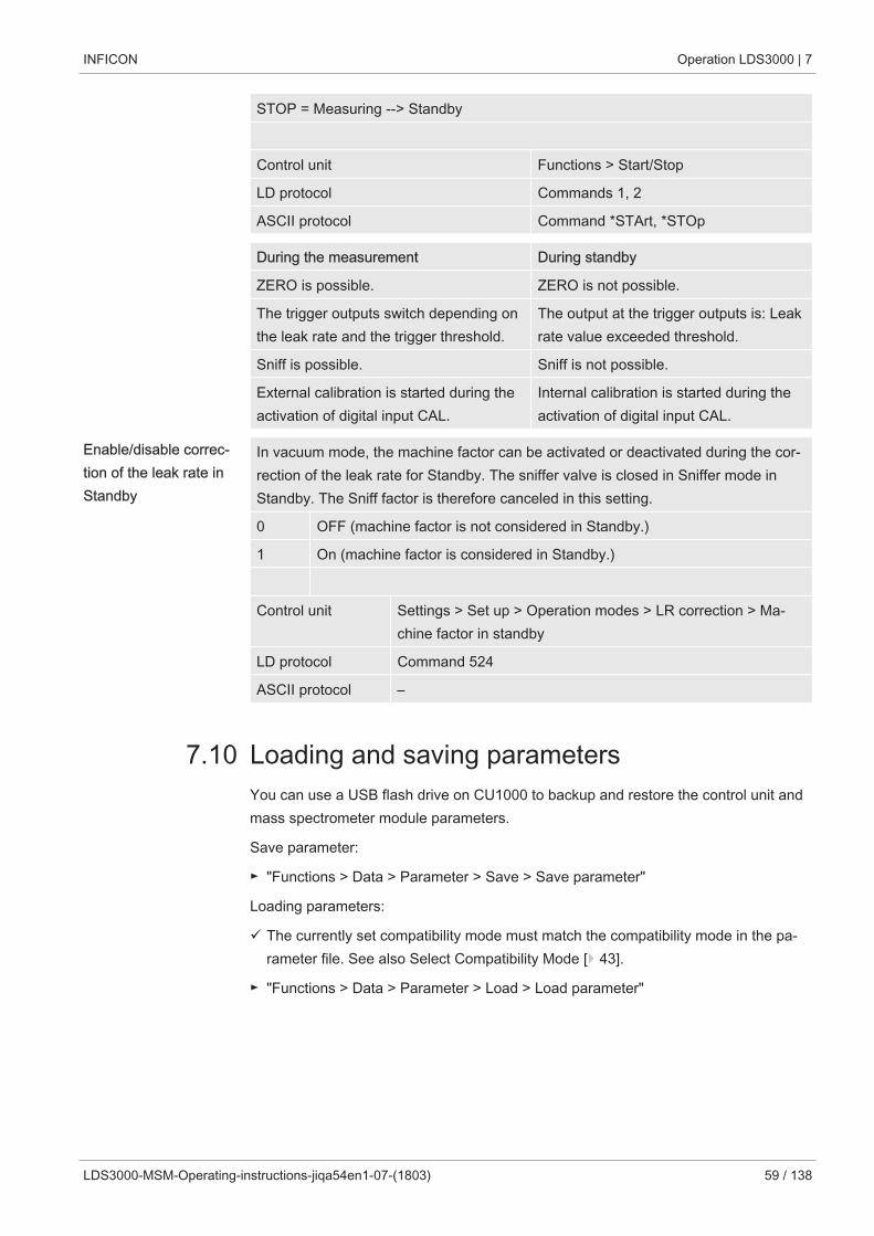
INFICON Operation LDS3000 | 7
LDS3000-MSM-Operating-instructions-jiqa54en1-07-(1803) 59 / 138
STOP = Measuring --> Standby
Control unit Functions > Start/Stop
LD protocol Commands 1, 2
ASCII protocol Command *STArt, *STOp
During the measurement During standby
ZERO is possible. ZERO is not possible.
The trigger outputs switch depending onthe leak rate and the trigger threshold.
The output at the trigger outputs is: Leakrate value exceeded threshold.
Sniff is possible. Sniff is not possible.
External calibration is started during theactivation of digital input CAL.
Internal calibration is started during theactivation of digital input CAL.
Enable/disable correc-tion of the leak rate inStandby
In vacuum mode, the machine factor can be activated or deactivated during the cor-rection of the leak rate for Standby. The sniffer valve is closed in Sniffer mode inStandby. The Sniff factor is therefore canceled in this setting.
0 OFF (machine factor is not considered in Standby.)
1 On (machine factor is considered in Standby.)
Control unit Settings > Set up > Operation modes > LR correction > Ma-chine factor in standby
LD protocol Command 524
ASCII protocol –
7.10 Loading and saving parametersYou can use a USB flash drive on CU1000 to backup and restore the control unit andmass spectrometer module parameters.
Save parameter:
► "Functions > Data > Parameter > Save > Save parameter"
Loading parameters:
ü The currently set compatibility mode must match the compatibility mode in the pa-rameter file. See also Select Compatibility Mode [} 43].
► "Functions > Data > Parameter > Load > Load parameter"
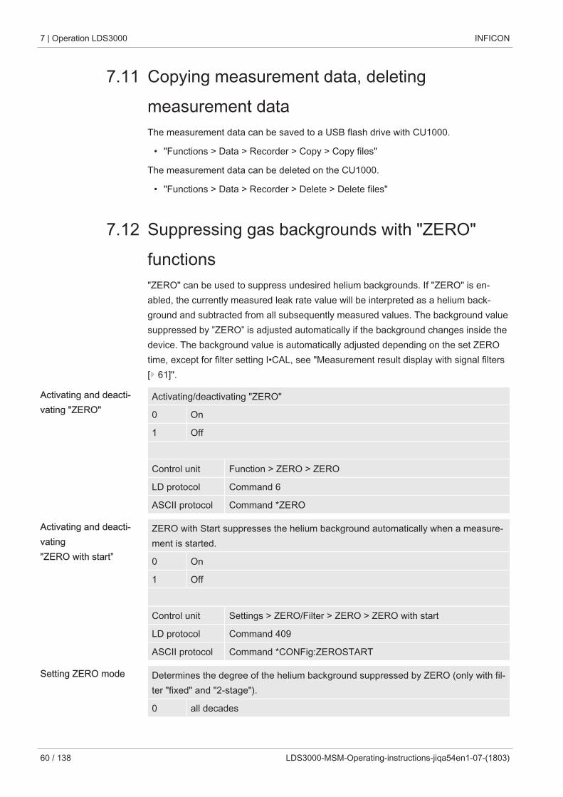
7 | Operation LDS3000 INFICON
60 / 138 LDS3000-MSM-Operating-instructions-jiqa54en1-07-(1803)
7.11 Copying measurement data, deletingmeasurement dataThe measurement data can be saved to a USB flash drive with CU1000.
• "Functions > Data > Recorder > Copy > Copy files"
The measurement data can be deleted on the CU1000.
• "Functions > Data > Recorder > Delete > Delete files"
7.12 Suppressing gas backgrounds with "ZERO"functions"ZERO" can be used to suppress undesired helium backgrounds. If "ZERO" is en-abled, the currently measured leak rate value will be interpreted as a helium back-ground and subtracted from all subsequently measured values. The background valuesuppressed by ”ZERO” is adjusted automatically if the background changes inside thedevice. The background value is automatically adjusted depending on the set ZEROtime, except for filter setting I•CAL, see "Measurement result display with signal filters[} 61]".
Activating and deacti-vating "ZERO"
Activating/deactivating "ZERO"
0 On
1 Off
Control unit Function > ZERO > ZERO
LD protocol Command 6
ASCII protocol Command *ZERO
Activating and deacti-vating "ZERO with start”
ZERO with Start suppresses the helium background automatically when a measure-ment is started.
0 On
1 Off
Control unit Settings > ZERO/Filter > ZERO > ZERO with start
LD protocol Command 409
ASCII protocol Command *CONFig:ZEROSTART
Setting ZERO mode Determines the degree of the helium background suppressed by ZERO (only with fil-ter "fixed" and "2-stage").
0 all decades
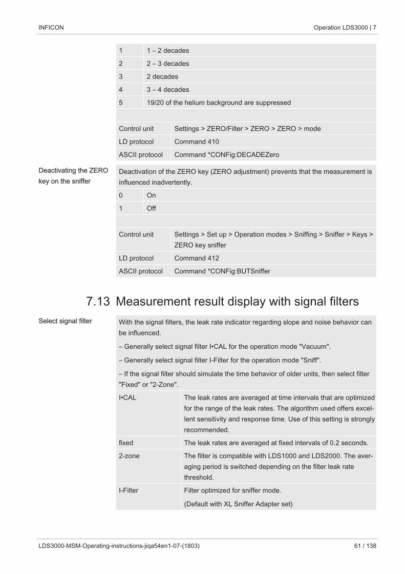
INFICON Operation LDS3000 | 7
LDS3000-MSM-Operating-instructions-jiqa54en1-07-(1803) 61 / 138
1 1 – 2 decades
2 2 – 3 decades
3 2 decades
4 3 – 4 decades
5 19/20 of the helium background are suppressed
Control unit Settings > ZERO/Filter > ZERO > ZERO > mode
LD protocol Command 410
ASCII protocol Command *CONFig:DECADEZero
Deactivating the ZEROkey on the sniffer
Deactivation of the ZERO key (ZERO adjustment) prevents that the measurement isinfluenced inadvertently.
0 On
1 Off
Control unit Settings > Set up > Operation modes > Sniffing > Sniffer > Keys >ZERO key sniffer
LD protocol Command 412
ASCII protocol Command *CONFig:BUTSniffer
7.13 Measurement result display with signal filtersSelect signal filter With the signal filters, the leak rate indicator regarding slope and noise behavior can
be influenced.
– Generally select signal filter I•CAL for the operation mode "Vacuum".
– Generally select signal filter I-Filter for the operation mode "Sniff".
– If the signal filter should simulate the time behavior of older units, then select filter"Fixed" or "2-Zone".
I•CAL The leak rates are averaged at time intervals that are optimizedfor the range of the leak rates. The algorithm used offers excel-lent sensitivity and response time. Use of this setting is stronglyrecommended.
fixed The leak rates are averaged at fixed intervals of 0.2 seconds.
2-zone The filter is compatible with LDS1000 and LDS2000. The aver-aging period is switched depending on the filter leak ratethreshold.
I-Filter Filter optimized for sniffer mode.
(Default with XL Sniffer Adapter set)
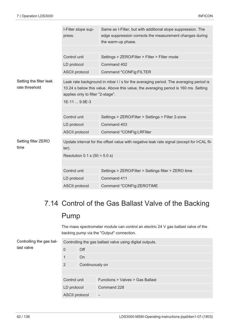
7 | Operation LDS3000 INFICON
62 / 138 LDS3000-MSM-Operating-instructions-jiqa54en1-07-(1803)
I-Filter slope sup-press.
Same as I-Filter, but with additional slope suppression. Theedge suppression corrects the measurement changes duringthe warm-up phase.
Control unit Settings > ZERO/Filter > Filter > Filter mode
LD protocol Command 402
ASCII protocol Command *CONFig:FILTER
Setting the filter leakrate threshold
Leak rate background in mbar l / s for the averaging period. The averaging period is10.24 s below this value. Above this value, the averaging period is 160 ms. Settingapplies only to filter "2-stage".
1E-11 ... 9.9E-3
Control unit Settings > ZERO/Filter > Settings > Filter 2-zone
LD protocol Command 403
ASCII protocol Command *CONFig:LRFilter
Setting filter ZEROtime
Update interval for the offset value with negative leak rate signal (except for I•CAL fil-ter).
Resolution 0.1 s (50 = 5.0 s)
Control unit Settings > ZERO/Filter > Settings filter > ZERO time
LD protocol Command 411
ASCII protocol Command *CONFig:ZEROTIME
7.14 Control of the Gas Ballast Valve of the BackingPumpThe mass spectrometer module can control an electric 24 V gas ballast valve of thebacking pump via the "Output" connection.
Controlling the gas bal-last valve
Controlling the gas ballast valve using digital outputs.
0 Off
1 On
2 Continuously on
Control unit Functions > Valves > Gas Ballast
LD protocol Command 228
ASCII protocol –
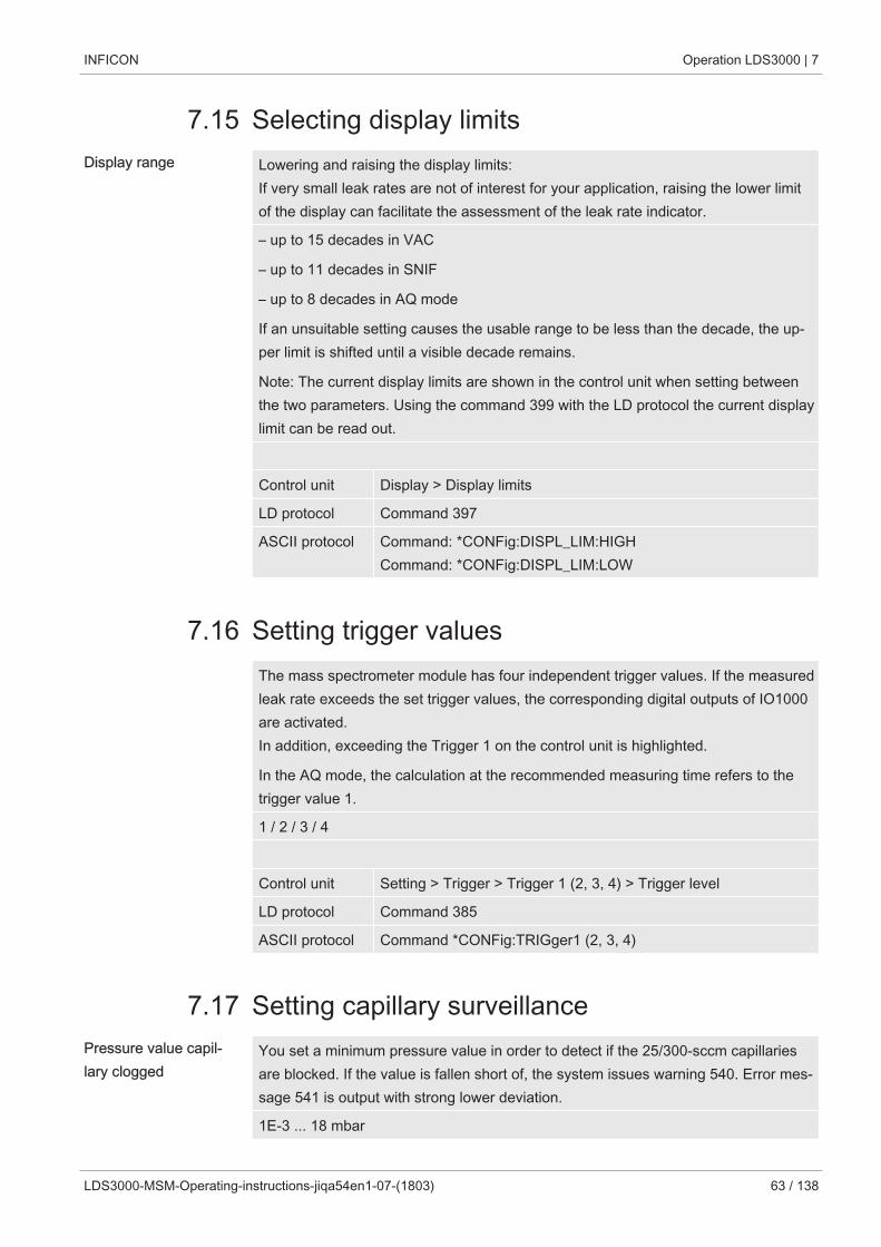
INFICON Operation LDS3000 | 7
LDS3000-MSM-Operating-instructions-jiqa54en1-07-(1803) 63 / 138
7.15 Selecting display limitsDisplay range Lowering and raising the display limits:
If very small leak rates are not of interest for your application, raising the lower limitof the display can facilitate the assessment of the leak rate indicator.
– up to 15 decades in VAC
– up to 11 decades in SNIF
– up to 8 decades in AQ mode
If an unsuitable setting causes the usable range to be less than the decade, the up-per limit is shifted until a visible decade remains.
Note: The current display limits are shown in the control unit when setting betweenthe two parameters. Using the command 399 with the LD protocol the current displaylimit can be read out.
Control unit Display > Display limits
LD protocol Command 397
ASCII protocol Command: *CONFig:DISPL_LIM:HIGHCommand: *CONFig:DISPL_LIM:LOW
7.16 Setting trigger valuesThe mass spectrometer module has four independent trigger values. If the measuredleak rate exceeds the set trigger values, the corresponding digital outputs of IO1000are activated.In addition, exceeding the Trigger 1 on the control unit is highlighted.
In the AQ mode, the calculation at the recommended measuring time refers to thetrigger value 1.
1 / 2 / 3 / 4
Control unit Setting > Trigger > Trigger 1 (2, 3, 4) > Trigger level
LD protocol Command 385
ASCII protocol Command *CONFig:TRIGger1 (2, 3, 4)
7.17 Setting capillary surveillancePressure value capil-lary clogged
You set a minimum pressure value in order to detect if the 25/300-sccm capillariesare blocked. If the value is fallen short of, the system issues warning 540. Error mes-sage 541 is output with strong lower deviation.
1E-3 ... 18 mbar
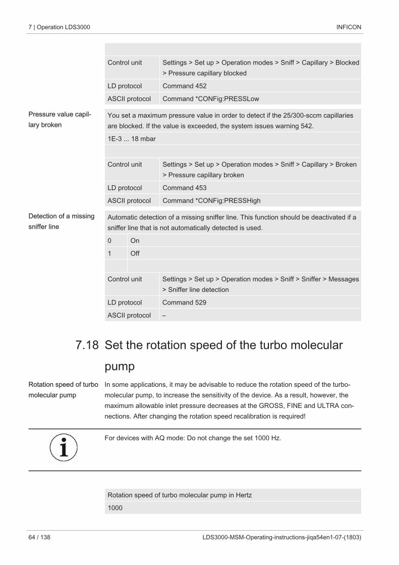
7 | Operation LDS3000 INFICON
64 / 138 LDS3000-MSM-Operating-instructions-jiqa54en1-07-(1803)
Control unit Settings > Set up > Operation modes > Sniff > Capillary > Blocked> Pressure capillary blocked
LD protocol Command 452
ASCII protocol Command *CONFig:PRESSLow
Pressure value capil-lary broken
You set a maximum pressure value in order to detect if the 25/300-sccm capillariesare blocked. If the value is exceeded, the system issues warning 542.
1E-3 ... 18 mbar
Control unit Settings > Set up > Operation modes > Sniff > Capillary > Broken> Pressure capillary broken
LD protocol Command 453
ASCII protocol Command *CONFig:PRESSHigh
Detection of a missingsniffer line
Automatic detection of a missing sniffer line. This function should be deactivated if asniffer line that is not automatically detected is used.
0 On
1 Off
Control unit Settings > Set up > Operation modes > Sniff > Sniffer > Messages> Sniffer line detection
LD protocol Command 529
ASCII protocol –
7.18 Set the rotation speed of the turbo molecularpump
Rotation speed of turbomolecular pump
In some applications, it may be advisable to reduce the rotation speed of the turbo-molecular pump, to increase the sensitivity of the device. As a result, however, themaximum allowable inlet pressure decreases at the GROSS, FINE and ULTRA con-nections. After changing the rotation speed recalibration is required!
For devices with AQ mode: Do not change the set 1000 Hz.
Rotation speed of turbo molecular pump in Hertz
1000
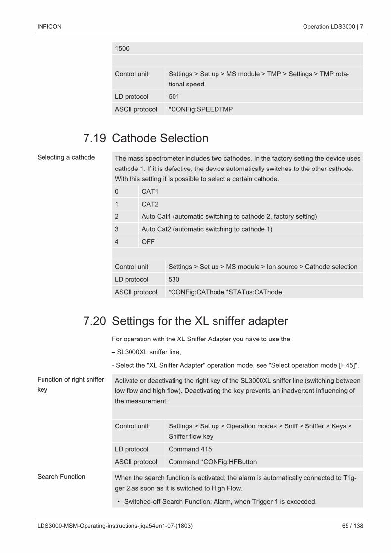
INFICON Operation LDS3000 | 7
LDS3000-MSM-Operating-instructions-jiqa54en1-07-(1803) 65 / 138
1500
Control unit Settings > Set up > MS module > TMP > Settings > TMP rota-tional speed
LD protocol 501
ASCII protocol *CONFig:SPEEDTMP
7.19 Cathode SelectionSelecting a cathode The mass spectrometer includes two cathodes. In the factory setting the device uses
cathode 1. If it is defective, the device automatically switches to the other cathode.With this setting it is possible to select a certain cathode.
0 CAT1
1 CAT2
2 Auto Cat1 (automatic switching to cathode 2, factory setting)
3 Auto Cat2 (automatic switching to cathode 1)
4 OFF
Control unit Settings > Set up > MS module > Ion source > Cathode selection
LD protocol 530
ASCII protocol *CONFig:CAThode *STATus:CAThode
7.20 Settings for the XL sniffer adapterFor operation with the XL Sniffer Adapter you have to use the
– SL3000XL sniffer line,
- Select the "XL Sniffer Adapter" operation mode, see "Select operation mode [} 45]".
Function of right snifferkey
Activate or deactivating the right key of the SL3000XL sniffer line (switching betweenlow flow and high flow). Deactivating the key prevents an inadvertent influencing ofthe measurement.
Control unit Settings > Set up > Operation modes > Sniff > Sniffer > Keys >Sniffer flow key
LD protocol Command 415
ASCII protocol Command *CONFig:HFButton
Search Function When the search function is activated, the alarm is automatically connected to Trig-ger 2 as soon as it is switched to High Flow.
• Switched-off Search Function: Alarm, when Trigger 1 is exceeded.
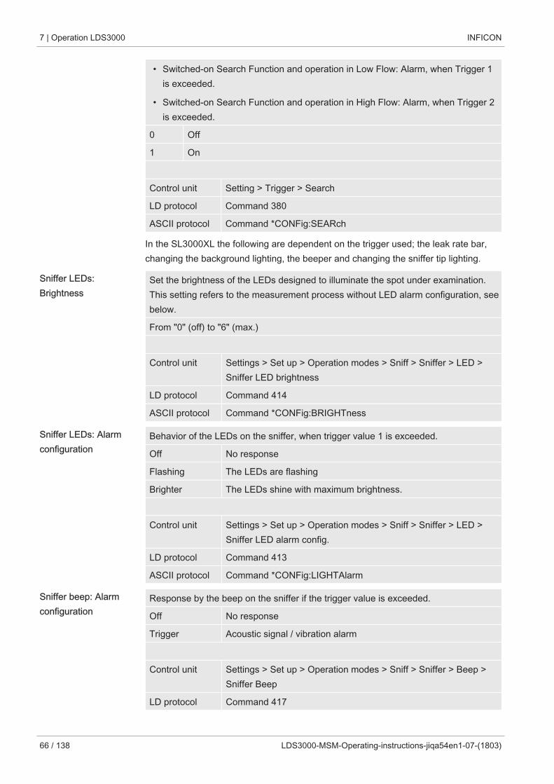
7 | Operation LDS3000 INFICON
66 / 138 LDS3000-MSM-Operating-instructions-jiqa54en1-07-(1803)
• Switched-on Search Function and operation in Low Flow: Alarm, when Trigger 1is exceeded.
• Switched-on Search Function and operation in High Flow: Alarm, when Trigger 2is exceeded.
0 Off
1 On
Control unit Setting > Trigger > Search
LD protocol Command 380
ASCII protocol Command *CONFig:SEARch
In the SL3000XL the following are dependent on the trigger used; the leak rate bar,changing the background lighting, the beeper and changing the sniffer tip lighting.
Sniffer LEDs: Brightness
Set the brightness of the LEDs designed to illuminate the spot under examination.This setting refers to the measurement process without LED alarm configuration, seebelow.
From "0" (off) to "6" (max.)
Control unit Settings > Set up > Operation modes > Sniff > Sniffer > LED >Sniffer LED brightness
LD protocol Command 414
ASCII protocol Command *CONFig:BRIGHTness
Sniffer LEDs: Alarmconfiguration
Behavior of the LEDs on the sniffer, when trigger value 1 is exceeded.
Off No response
Flashing The LEDs are flashing
Brighter The LEDs shine with maximum brightness.
Control unit Settings > Set up > Operation modes > Sniff > Sniffer > LED >Sniffer LED alarm config.
LD protocol Command 413
ASCII protocol Command *CONFig:LIGHTAlarm
Sniffer beep: Alarmconfiguration
Response by the beep on the sniffer if the trigger value is exceeded.
Off No response
Trigger Acoustic signal / vibration alarm
Control unit Settings > Set up > Operation modes > Sniff > Sniffer > Beep >Sniffer Beep
LD protocol Command 417
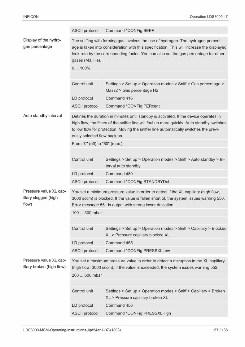
INFICON Operation LDS3000 | 7
LDS3000-MSM-Operating-instructions-jiqa54en1-07-(1803) 67 / 138
ASCII protocol Command *CONFig:BEEP
Display of the hydro-gen percentage
The sniffing with forming gas involves the use of hydrogen. The hydrogen percent-age is taken into consideration with this specification. This will increase the displayedleak rate by the corresponding factor. You can also set the gas percentage for othergases (M3, He).
0 ... 100%
Control unit Settings > Set up > Operation modes > Sniff > Gas percentage >Mass2 > Gas percentage H2
LD protocol Command 416
ASCII protocol Command *CONFig:PERcent
Auto standby interval Defines the duration in minutes until standby is activated. If the device operates inhigh flow, the filters of the sniffer line will foul up more quickly. Auto standby switchesto low flow for protection. Moving the sniffer line automatically switches the previ-ously selected flow back on.
From "0" (off) to "60" (max.)
Control unit Settings > Set up > Operation modes > Sniff > Auto standby > In-terval auto standby
LD protocol Command 480
ASCII protocol Command *CONFig:STANDBYDel
Pressure value XL cap-illary clogged (highflow)
You set a minimum pressure value in order to detect if the XL capillary (high flow,3000 sccm) is blocked. If the value is fallen short of, the system issues warning 550.Error message 551 is output with strong lower deviation.
100 ... 300 mbar
Control unit Settings > Set up > Operation modes > Sniff > Capillary > BlockedXL > Pressure capillary blocked XL
LD protocol Command 455
ASCII protocol Command *CONFig:PRESSXLLow
Pressure value XL cap-illary broken (high flow)
You set a maximum pressure value in order to detect a disruption in the XL capillary(high flow, 3000 sccm). If the value is exceeded, the system issues warning 552.
200 ... 600 mbar
Control unit Settings > Set up > Operation modes > Sniff > Capillary > BrokenXL > Pressure capillary broken XL
LD protocol Command 456
ASCII protocol Command *CONFig:PRESSXLHigh
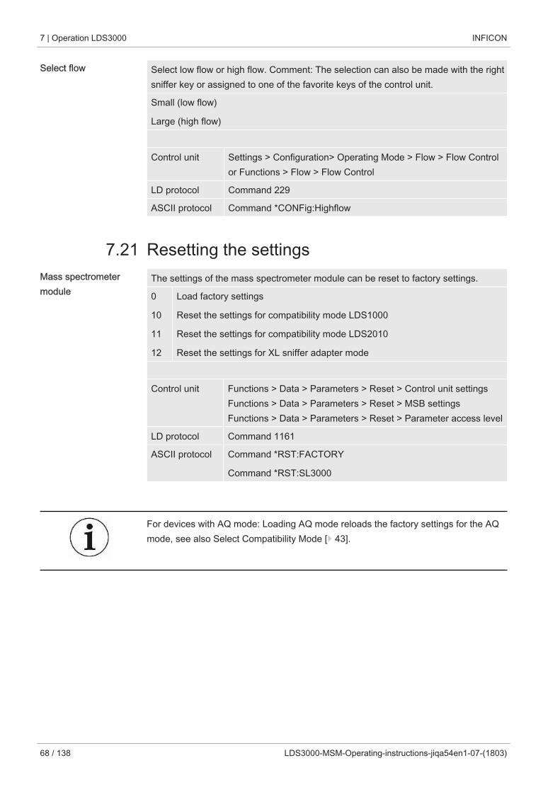
7 | Operation LDS3000 INFICON
68 / 138 LDS3000-MSM-Operating-instructions-jiqa54en1-07-(1803)
Select flow Select low flow or high flow. Comment: The selection can also be made with the rightsniffer key or assigned to one of the favorite keys of the control unit.
Small (low flow)
Large (high flow)
Control unit Settings > Configuration> Operating Mode > Flow > Flow Controlor Functions > Flow > Flow Control
LD protocol Command 229
ASCII protocol Command *CONFig:Highflow
7.21 Resetting the settingsMass spectrometermodule
The settings of the mass spectrometer module can be reset to factory settings.
0
10
11
12
Load factory settings
Reset the settings for compatibility mode LDS1000
Reset the settings for compatibility mode LDS2010
Reset the settings for XL sniffer adapter mode
Control unit Functions > Data > Parameters > Reset > Control unit settingsFunctions > Data > Parameters > Reset > MSB settingsFunctions > Data > Parameters > Reset > Parameter access level
LD protocol Command 1161
ASCII protocol Command *RST:FACTORY
Command *RST:SL3000
For devices with AQ mode: Loading AQ mode reloads the factory settings for the AQmode, see also Select Compatibility Mode [} 43].
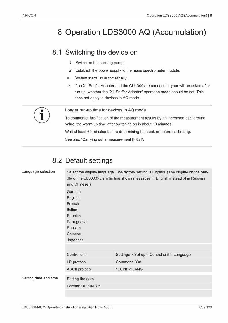
INFICON Operation LDS3000 AQ (Accumulation) | 8
LDS3000-MSM-Operating-instructions-jiqa54en1-07-(1803) 69 / 138
8 Operation LDS3000 AQ (Accumulation)
8.1 Switching the device on1 Switch on the backing pump.
2 Establish the power supply to the mass spectrometer module.
ð System starts up automatically.
ð If an XL Sniffer Adapter and the CU1000 are connected, your will be asked afterrun-up, whether the "XL Sniffer Adapter" operation mode should be set. Thisdoes not apply to devices in AQ mode.
Longer run-up time for devices in AQ mode
To counteract falsification of the measurement results by an increased backgroundvalue, the warm-up time after switching on is about 10 minutes.
Wait at least 60 minutes before determining the peak or before calibrating.
See also “Carrying out a measurement [} 82]“.
8.2 Default settingsLanguage selection Select the display language. The factory setting is English. (The display on the han-
dle of the SL3000XL sniffer line shows messages in English instead of in Russianand Chinese.)
GermanEnglishFrenchItalianSpanishPortugueseRussianChineseJapanese
Control unit Settings > Set up > Control unit > Language
LD protocol Command 398
ASCII protocol *CONFig:LANG
Setting date and time Setting the date
Format: DD.MM.YY
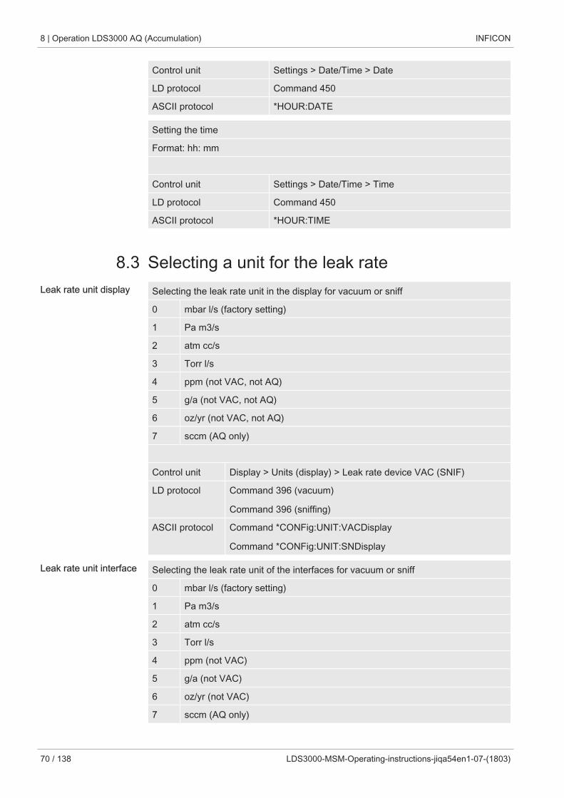
8 | Operation LDS3000 AQ (Accumulation) INFICON
70 / 138 LDS3000-MSM-Operating-instructions-jiqa54en1-07-(1803)
Control unit Settings > Date/Time > Date
LD protocol Command 450
ASCII protocol *HOUR:DATE
Setting the time
Format: hh: mm
Control unit Settings > Date/Time > Time
LD protocol Command 450
ASCII protocol *HOUR:TIME
8.3 Selecting a unit for the leak rateLeak rate unit display Selecting the leak rate unit in the display for vacuum or sniff
0 mbar l/s (factory setting)
1 Pa m3/s
2 atm cc/s
3 Torr l/s
4 ppm (not VAC, not AQ)
5 g/a (not VAC, not AQ)
6 oz/yr (not VAC, not AQ)
7 sccm (AQ only)
Control unit Display > Units (display) > Leak rate device VAC (SNIF)
LD protocol Command 396 (vacuum)
Command 396 (sniffing)
ASCII protocol Command *CONFig:UNIT:VACDisplay
Command *CONFig:UNIT:SNDisplay
Leak rate unit interface Selecting the leak rate unit of the interfaces for vacuum or sniff
0 mbar l/s (factory setting)
1 Pa m3/s
2 atm cc/s
3 Torr l/s
4 ppm (not VAC)
5 g/a (not VAC)
6 oz/yr (not VAC)
7 sccm (AQ only)
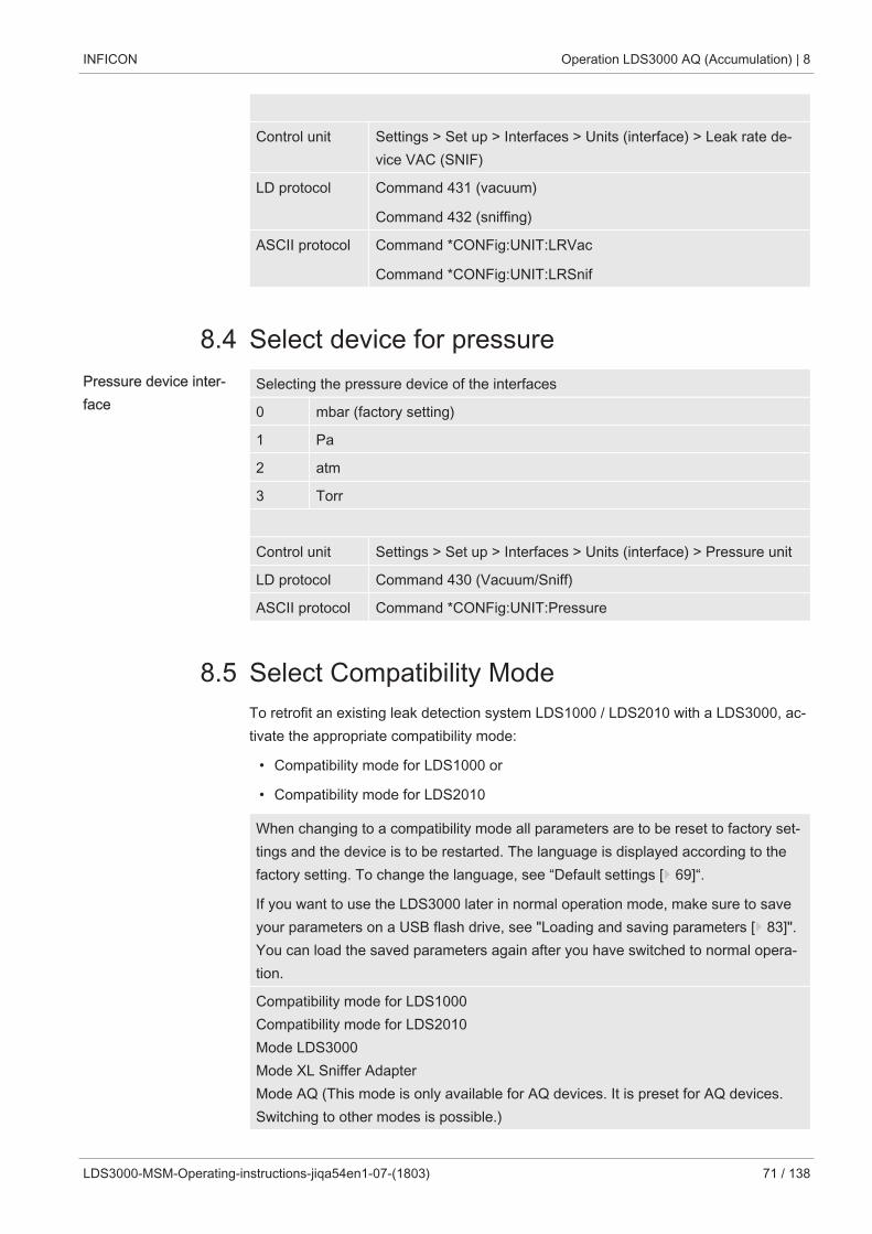
INFICON Operation LDS3000 AQ (Accumulation) | 8
LDS3000-MSM-Operating-instructions-jiqa54en1-07-(1803) 71 / 138
Control unit Settings > Set up > Interfaces > Units (interface) > Leak rate de-vice VAC (SNIF)
LD protocol Command 431 (vacuum)
Command 432 (sniffing)
ASCII protocol Command *CONFig:UNIT:LRVac
Command *CONFig:UNIT:LRSnif
8.4 Select device for pressurePressure device inter-face
Selecting the pressure device of the interfaces
0 mbar (factory setting)
1 Pa
2 atm
3 Torr
Control unit Settings > Set up > Interfaces > Units (interface) > Pressure unit
LD protocol Command 430 (Vacuum/Sniff)
ASCII protocol Command *CONFig:UNIT:Pressure
8.5 Select Compatibility ModeTo retrofit an existing leak detection system LDS1000 / LDS2010 with a LDS3000, ac-tivate the appropriate compatibility mode:
• Compatibility mode for LDS1000 or
• Compatibility mode for LDS2010
When changing to a compatibility mode all parameters are to be reset to factory set-tings and the device is to be restarted. The language is displayed according to thefactory setting. To change the language, see “Default settings [} 69]“.
If you want to use the LDS3000 later in normal operation mode, make sure to saveyour parameters on a USB flash drive, see "Loading and saving parameters [} 83]".You can load the saved parameters again after you have switched to normal opera-tion.
Compatibility mode for LDS1000Compatibility mode for LDS2010Mode LDS3000Mode XL Sniffer AdapterMode AQ (This mode is only available for AQ devices. It is preset for AQ devices.Switching to other modes is possible.)
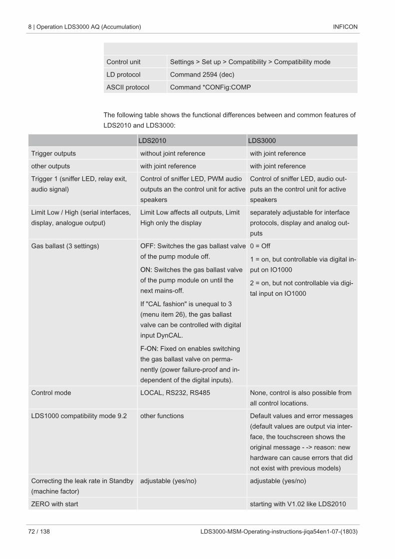
8 | Operation LDS3000 AQ (Accumulation) INFICON
72 / 138 LDS3000-MSM-Operating-instructions-jiqa54en1-07-(1803)
Control unit Settings > Set up > Compatibility > Compatibility mode
LD protocol Command 2594 (dec)
ASCII protocol Command *CONFig:COMP
The following table shows the functional differences between and common features ofLDS2010 and LDS3000:
LDS2010 LDS3000
Trigger outputs without joint reference with joint reference
other outputs with joint reference with joint reference
Trigger 1 (sniffer LED, relay exit,audio signal)
Control of sniffer LED, PWM audiooutputs an the control unit for activespeakers
Control of sniffer LED, audio out-puts an the control unit for activespeakers
Limit Low / High (serial interfaces,display, analogue output)
Limit Low affects all outputs, LimitHigh only the display
separately adjustable for interfaceprotocols, display and analog out-puts
Gas ballast (3 settings) OFF: Switches the gas ballast valveof the pump module off.
ON: Switches the gas ballast valveof the pump module on until thenext mains-off.
If "CAL fashion" is unequal to 3(menu item 26), the gas ballastvalve can be controlled with digitalinput DynCAL.
F-ON: Fixed on enables switchingthe gas ballast valve on perma-nently (power failure-proof and in-dependent of the digital inputs).
0 = Off
1 = on, but controllable via digital in-put on IO1000
2 = on, but not controllable via digi-tal input on IO1000
Control mode LOCAL, RS232, RS485 None, control is also possible fromall control locations.
LDS1000 compatibility mode 9.2 other functions Default values and error messages(default values are output via inter-face, the touchscreen shows theoriginal message - -> reason: newhardware can cause errors that didnot exist with previous models)
Correcting the leak rate in Standby(machine factor)
adjustable (yes/no) adjustable (yes/no)
ZERO with start starting with V1.02 like LDS2010
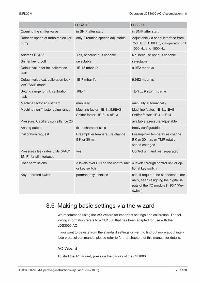
INFICON Operation LDS3000 AQ (Accumulation) | 8
LDS3000-MSM-Operating-instructions-jiqa54en1-07-(1803) 73 / 138
LDS2010 LDS3000
Opening the sniffer valve in SNIF after start in SNIF after start
Rotation speed of turbo molecularpump
only 2 rotation speeds adjustable Adjustable via serial interface from750 Hz to 1500 Hz, via operator unit1000 Hz and 1500 Hz
Address RS485 Yes, because bus capable No, because not bus capable
Sniffer key on/off selectable selectable
Default value for int. calibrationleak
1E-15 mbar l/s 9.9E2 mbar l/s
Default value ext. calibration leakVAC/SNIF mode
1E-7 mbar l/s 9.9E2 mbar l/s
Setting range for int. calibrationleak
10E-7 1E-9 ... 9.9E-1 mbar l/s
Machine factor adjustment manually manually/automatically
Machine / sniff factor value range Machine factor: 1E-3...9.9E+3Sniffer factor: 1E-3...9.9E+3
Machine factor: 1E-4...1E+5Sniffer factor: 1E-4...1E+4
Pressure: Capillary surveillance 20 available, pressure adjustable
Analog output fixed characteristics freely configurable
Calibration request Preamplifier temperature change5 K or 30 min
Preamplifier temperature change5 K or 30 min. or TMP rotationspeed changed
Pressure / leak rates units (VAC/SNIF) for all interfaces
yes Control unit and rest separated
User permissions 3 levels over PIN on the control unitor key switch
4 levels through control unit or op-tional key switch
Key-operated switch permanently installed can, if required, be connected exter-nally, see "Assigning the digital in-puts of the I/O module [} 95]" (Keyswitch)
8.6 Making basic settings via the wizardWe recommend using the AQ Wizard for important settings and calibration. The fol-lowing information refers to a CU1000 that has been adapted for use with theLDS3000 AQ.
If you want to deviate from the standard settings or want to find out more about inter-face protocol commands, please refer to further chapters of this manual for details.
AQ Wizard
To start the AQ wizard, press on the display of the CU1000
8 | Operation LDS3000 AQ (Accumulation) INFICON
74 / 138 LDS3000-MSM-Operating-instructions-jiqa54en1-07-(1803)
Main menu > Functions > Assistant
Alternatively press the word “Wizard” at the bottom of the display.
Make your entries in the windows that are called one after the other.
1. Chamber volume(net volume)The unit of volume can be selected under Main Menu > Settings > Set up > Op.modes > AQ > Volume unit.(LD protocol: Command 1763ASCII protocol: *CONFig:AQ:VOLume)
2. Trigger level 1(LD/ASCII protocol: See "Setting trigger values [} 63]")
3. Mass(selection between helium or forming gas)(LD/ASCII protocol: See "Select gas type (mass) [} 46]"
4. Percentage of gas(for example, the hydrogen content in forming gas)(LD/ASCII protocol: See display of hydrogen content in “Settings for the XL snifferadapter [} 65]“
5. Measurement time(The time can be freely adjusted, but there is also a recommendation, dependingon parameters.)(LD protocol: Command 1765ASCII protocol: *CONFig:AQ:TIME)
Alternatively, you can make your settings in the following places:
Main menu > Settings > Set up > Operation modes > AQ
Main menu > Settings > Mass
8.7 Determine peakTo obtain the most accurate measurement results, you should always determine thecurrent "peak" before calibration. At the end of this process, the value for the old an-ode voltage is replaced by the value for the new anode voltage.
The adjustment uses air-helium or air-hydrogen. An adjustment only with nitrogen isnot possible.
The following information about the display refers to a CU1000 that has been adaptedfor use with the LDS3000 AQ.
ü To prevent falsification of measurement results due to an increased backgroundvalue, you have waited for at least 60 minutes to warm up.
1 Main menu > Functions > CAL > Peak.
INFICON Operation LDS3000 AQ (Accumulation) | 8
LDS3000-MSM-Operating-instructions-jiqa54en1-07-(1803) 75 / 138
2 Confirm with “OK”.
ð The "CAL peak" window opens.
3 Remove the calibration leak from the chamber.
4 Wait until the background signal is stable.
5 To confirm the stable background value and start the adjustment, confirm with"OK".
ð (LD protocol: 4, Parameter 7 (peak adjust AQ)ASCII protocol: *CAL:PEAK)IO1000: "Peakfind” input
ð (LD and ASCII protocol: The status must then be queried via command 260(State Calibration) or *STATus: CAL)
ð After adjustment, the old and new anode voltage are displayed.
8.8 Store leak rate of calibration leaksEnter the specifications for the used calibration leak once. A specific leak rate must beset for each gas (mass).Range: 1E-9 ... 9.9E-2 mbar l/s
Minimum size for leak rate of the calibration leak
In order to perform a stable calibration, we recommend a minimum size for the leakrate of the used calibration leak.
If the measurement time proposed by the AQ Wizard is maintained, the leak rateshould not fall below the following value:
- When using forming gas, the selected setpoint (Trigger 1)
- When using helium 1/5 of the selected setpoint (Trigger 1)
If the leak rate of the used calibration leak is too small, an error message will be is-sued to start or finish the calibration.
The following information refers to a CU1000 that has been adapted for use with theLDS3000 AQ.
ü The desired unit in which you want to enter the leak rate is set. If the unit of leakrate displayed in your system differs from the unit indicated on the calibration leak,at least temporarily set the unit as indicated on the calibration leak. See also “Se-lecting a unit for the leak rate [} 42]“.
1 Main menu > Functions > CAL > Settings > Ext. calibration leak
2 Enter the desired gas and the associated leak rate.(LD protocol: Command 390ASCII protocol: *CONFig:CALleak:EXTVac)
8 | Operation LDS3000 AQ (Accumulation) INFICON
76 / 138 LDS3000-MSM-Operating-instructions-jiqa54en1-07-(1803)
8.9 Calibrating the device
8.9.1 Time and general preferences
NOTICE
Incorrect calibration because of operating temperature that is too low
Calibrating the device in the cold state can deliver incorrect measurement results.
► For optimum accuracy the device should have been turned on at least 60 minutespreviously.
It is recommended to calibrate the device once per shift in the desired operatingmodes and for the desired gases. Thereafter you can switch between the operationmodes and gases without re-calibrating.
Further, calibration is required after a calibration prompt by the system.
Switching off thepreamplifier test
The device tests the installed preamplifier during calibration. You can switch off ofthe amplifier test. This increases the speed of the calibration, but reliability drops off.
0 OFF
1 ON
Control unit Settings > Set-up> MS-module > Preamplifier > Test >Preamplifier test with CAL
LD protocol Command 370
ASCII protocol Command *CONFig:AMPTest (ON,OFF)
Enabling calibration re-quest
If Calibration request is enabled, the device will prompt the operator to perform a cal-ibration 30 minutes after it has been switched on and in case of temperaturechanges greater than 5°C.
0 OFF
1 ON
Control unit Functions > CAL > Settings > CAL request. > Calibration re-quest
or
Settings > Set-up> CAL request. > Calibration request
LD protocol Command 419
INFICON Operation LDS3000 AQ (Accumulation) | 8
LDS3000-MSM-Operating-instructions-jiqa54en1-07-(1803) 77 / 138
ASCII protocol *CONFig:CALREQ (ON,OFF)
Calibration warningWrn650
The warning message Wrn650 "Calibration within the first 20 minutes is not recom-mended" can be allowed or suppressed.
0 OFF (suppressed)
1 ON (allowed)
Control unit Functions > CAL > Settings > CAL request. > Calibrationwarning W650
or
Settings > Set-up> CAL request. > Calibration warningW650
LD protocol Command 429
ASCII protocol *CONFig:CALWarn ON (OFF)
See also
2 Setting machine and sniff factor [} 81]
8.9.2 Entering the calibration factorThe calibration is usually determined by the appropriate calibration routine. Therefore,it is usually not necessary to adjust the calibration factor manually.
An incorrectly set calibration inevitably leads to wrong leak rate indicator!
8.9.3 Calibration factor vacuumAlso applies to devices in AQ mode.
Entry of calibration factors for masses 2, 3, 4.
The values will be overwritten during the next calibration.
0.01 … 5000
Control unit Settings > Set up > Operation modes > Vacuum > Calibr. factor> mass 2 (3, 4) > calibration factor VAC H2 (M3, He)
LD protocol Command 520
ASCII protocol Command *FACtor:CALVac
8 | Operation LDS3000 AQ (Accumulation) INFICON
78 / 138 LDS3000-MSM-Operating-instructions-jiqa54en1-07-(1803)
8.9.4 CalibratingPlease also note the general instructions for calibration, see “Calibrating the device[} 47]“.
Requirements for all procedures
• You have an external calibration leak.
• The information on the calibration leak is entered, see also “Store leak rate of cali-bration leaks [} 75]“.
• To prevent falsification of measurement results due to an increased backgroundvalue, you have waited for at least 60 minutes to warm up.
• The current "peak" was determined, see also “Determine peak [} 74]“.
Control unit CU1000
1 Place the open calibration leak in the measuring chamber and close the mea-suring chamber.
2 Main menu > Functions > CAL > external
ð The leak rate of the calibration leak will be displayed and a question to startthe calibration.
3 To start the calbration confirm with “OK“.
4 Follow the instructions on the screen.
LD or ASCII protocol, IO1000
1 Place the open calibration leak in the measuring chamber and close the mea-suring chamber.
2 For a stable leak rate signal, wait at least the duration of the set AQ measure-ment time.
3 Start the calibrationLD protocol: Command 4, Parameter 1ASCII protocol: *CAL:EXTIO1000: Input "CAL external", see also the following figure
ð If helium is used, proceed to the last step (no. 8).
4 For a background determination of forming gas (hydrogen), then query the sta-tus:LD protocol: Command 260 (State Calibration) ASCII protocol: *STATus:CAL
ð Wait until it reaches the following state:LD protocol: Command 260 State 75 “WAIT_ZERO_AQ“ASCII protocol: *STATus:CAL? on “CLOSE“IO1000: Input "CAL stable", see also the following figure
INFICON Operation LDS3000 AQ (Accumulation) | 8
LDS3000-MSM-Operating-instructions-jiqa54en1-07-(1803) 79 / 138
5 Remove the calibration leak from the measuring chamber and close the measur-ing chamber.
6 For a stable leak rate signal, wait at least the duration of the set AQ measure-ment time.
7 Start the background measurement.LD protocol: Command 11, Parameter 1 (Continue calibration)ASCII protocol: *CAL:CLOSEDIO1000: Input "CAL external", see also the following figure
8 Then query the status:LD protocol: Command 260 (State Calibration) ASCII protocol: *STATus:CAL
ð Wait until it reaches the following state:LD protocol: Command 260 State 0 “READY“ASCII protocol: *STATus:CAL? on “IDLE“IO1000: Output "CAL active", see also the following figure
ð The calibration is completed.
ð In case of error:LD protocol: Command 260 State 51...59 (error conditions)ASCII protocol: *STATus:CAL? on “FAIL“IO1000: Output "Error or Warning”
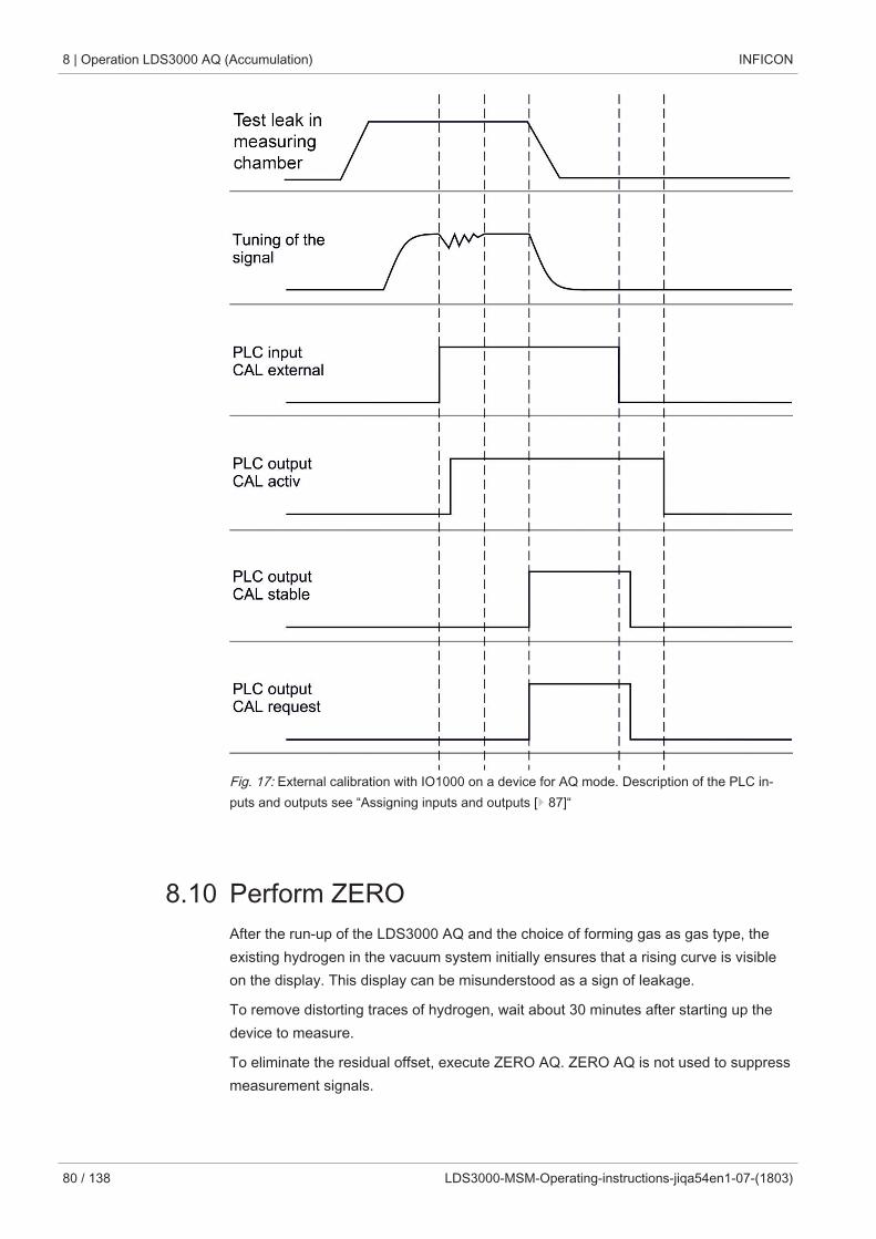
8 | Operation LDS3000 AQ (Accumulation) INFICON
80 / 138 LDS3000-MSM-Operating-instructions-jiqa54en1-07-(1803)
Fig. 17: External calibration with IO1000 on a device for AQ mode. Description of the PLC in-puts and outputs see “Assigning inputs and outputs [} 87]“
8.10 Perform ZEROAfter the run-up of the LDS3000 AQ and the choice of forming gas as gas type, theexisting hydrogen in the vacuum system initially ensures that a rising curve is visibleon the display. This display can be misunderstood as a sign of leakage.
To remove distorting traces of hydrogen, wait about 30 minutes after starting up thedevice to measure.
To eliminate the residual offset, execute ZERO AQ. ZERO AQ is not used to suppressmeasurement signals.
INFICON Operation LDS3000 AQ (Accumulation) | 8
LDS3000-MSM-Operating-instructions-jiqa54en1-07-(1803) 81 / 138
ü Mass is hydrogen (forming gas).If no hydrogen (forming gas) is entered, you can set it under "Main menu > Settings> Mass" or via "Wizard" at the bottom of the measurement window display.
ü There is neither a test specimen nor a calibration leak in the measuring chamber.
1 Main menu > Functions > ZERO AQ
2 Follow the instructions on the screen.
ð LD and ASCII protocol: After removing the test specimen or calibration leak,first wait for the measuring time.
ð LD protocol: Command 6, Parameter 1; ASCII protocol: *ZERO:ON
ð IO1000: Input ZERO
8.11 Setting machine and sniff factorThe internal calibration will only calibrate the measurement system of a mass spec-trometer module that is uncoupled from the test system. If the measurement system isoperated in parallel to an additional pump system after an internal calibration though(following the partial flow principle), the measurement system will indicate a leak ratethat is too low based on the partial flow ratio. With the help of a corrective machinefactor for vacuum mode and a sniff factor for sniffer mode, the measurement systemindicates the actual leak rate. The factors are taken into consideration along wit the ra-tio of effective pumping speed of the measurement system in a comparison to thepumping speed of the measurement system on the test system.
8.11.1 Setting machine and sniff factor manuallyü Mass spectrometer module calibrated internally.
1 Measure external calibration leak using the test system.
ð The device indicates a leak rate that is too low based on the partial flow ratio.
2 Setting machine or sniff factor, see below.
ð The device indicates the actual leak rate.Setting the machinefactor
Devices in AQ mode:
The machine factor "1" is preset. This setting should not be changed.
Corrects a possible deviation between internal and external calibration in vacuummode.
8 | Operation LDS3000 AQ (Accumulation) INFICON
82 / 138 LDS3000-MSM-Operating-instructions-jiqa54en1-07-(1803)
Should be at value 1.00 without the option internal calibration leak. After the value ischanged, the leak rate resulting from the change is displayed. This simplifies adjust-ment.
Value range 1E-4...1E+5
Control unit Settings > Set up > Operation modes > Vacuum > Machine fac-tor > Mass 2 (3, 4) > machine factor VAC H2 (M3, He)
LD protocol Command 522
ASCII protocol Command *FACtor:FACMachine
Setting the sniff factor Corrects a possible deviation between internal and external calibration in sniffermode
Value range 1E-4...1E+4
Control unit Settings > Set up > Operation modes > Sniffing > Sniff factorMass 2 (3, 4) > Sniff factor H2 (M3, He)
LD protocol Command 523
ASCII protocol Command *FACtor:FACSniff
8.12 Carrying out a measurement
WARNING
Danger due to imploding measuring chamber
An external measuring chamber connected to an LDS3000 AQ is pumped off at ap-proximately 60 sccm. Within normal measurement times (2 - 30 seconds) no danger-ous negative pressure is generated.
If the measuring chamber is leak-proof, but not vacuum resistant, and continues topump, it may implode. This can occur, for example, in a 1-liter measuring chamber af-ter about 10 minutes.
► Do not continue pumping a measuring chamber after the measuring time has ex-pired.
► Consider suitable protective measures!
ü The device is switched on.
ü The peak has been determined, see “Determine peak [} 74]“.
ü The calibration was done, see “Calibrating [} 78]“.
INFICON Operation LDS3000 AQ (Accumulation) | 8
LDS3000-MSM-Operating-instructions-jiqa54en1-07-(1803) 83 / 138
ü AQ ZERO has been determined, see “Perform ZERO [} 80]“.
1 If you are measuring with forming gas, make sure that the device has been run-ning for at least half an hour. This time is needed to perform stable measure-ments.
ð If you measure with helium, this waiting time is about 10 minutes.
2 Place the test object in the measuring chamber and close the measuring cham-ber. The test object should not be placed on the areas that may be leaking.
ð Either a test object filled with helium or forming gas under pressure is broughtinto the measuring chamber or pressurized in the measuring chamber.
ð If the test object leaks, the display shows an increasing leak rate.
3 Wait for the set measuring time.
ð The leak rate is calculated and displayed.
4 Remove the test object from the measuring chamber and continue the measure-ments with step 2.
ð Start or stop buttons are not used.
8.13 Loading and saving parametersYou can use a USB flash drive on CU1000 to backup and restore the control unit andmass spectrometer module parameters.
Save parameter:
► "Functions > Data > Parameter > Save > Save parameter"
Loading parameters:
ü The currently set compatibility mode must match the compatibility mode in the pa-rameter file. See also Select Compatibility Mode [} 71].
► "Functions > Data > Parameter > Load > Load parameter"
8.14 Copying measurement data, deletingmeasurement dataThe measurement data can be saved to a USB flash drive with CU1000.
• "Functions > Data > Recorder > Copy > Copy files"
The measurement data can be deleted on the CU1000.
• "Functions > Data > Recorder > Delete > Delete files"
8 | Operation LDS3000 AQ (Accumulation) INFICON
84 / 138 LDS3000-MSM-Operating-instructions-jiqa54en1-07-(1803)
8.15 Adjust ”Zero time factor AQ”In order to avoid apparently negative leak rates when measuring with forming gas, theleakage rate display is adjusted to 0 after a certain time (zero time factor AQ x mea-suring time).
Zero time factor AQ can be set under:
Main menu > Settings > Set up > Operation modes > AQ > Measurement time
The default value is 4 and can be changed to 1...10 in integers.
(LD protocol: Command 1767ASCII protocol: *CONFig:AQ:ZEROTime)
8.16 Selecting display limitsDisplay range Lowering and raising the display limits:
If very small leak rates are not of interest for your application, raising the lower limitof the display can facilitate the assessment of the leak rate indicator.
– up to 15 decades in VAC
– up to 11 decades in SNIF
– up to 8 decades in AQ mode
If an unsuitable setting causes the usable range to be less than the decade, the up-per limit is shifted until a visible decade remains.
Note: The current display limits are shown in the control unit when setting betweenthe two parameters. Using the command 399 with the LD protocol the current displaylimit can be read out.
Control unit Display > Display limits
LD protocol Command 397
ASCII protocol Command: *CONFig:DISPL_LIM:HIGHCommand: *CONFig:DISPL_LIM:LOW
8.17 Set the rotation speed of the turbo molecularpump
Rotation speed of turbomolecular pump
In some applications, it may be advisable to reduce the rotation speed of the turbo-molecular pump, to increase the sensitivity of the device. As a result, however, themaximum allowable inlet pressure decreases at the GROSS, FINE and ULTRA con-nections. After changing the rotation speed recalibration is required!
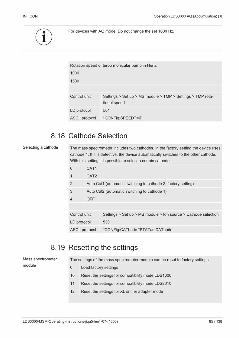
INFICON Operation LDS3000 AQ (Accumulation) | 8
LDS3000-MSM-Operating-instructions-jiqa54en1-07-(1803) 85 / 138
For devices with AQ mode: Do not change the set 1000 Hz.
Rotation speed of turbo molecular pump in Hertz
1000
1500
Control unit Settings > Set up > MS module > TMP > Settings > TMP rota-tional speed
LD protocol 501
ASCII protocol *CONFig:SPEEDTMP
8.18 Cathode SelectionSelecting a cathode The mass spectrometer includes two cathodes. In the factory setting the device uses
cathode 1. If it is defective, the device automatically switches to the other cathode.With this setting it is possible to select a certain cathode.
0 CAT1
1 CAT2
2 Auto Cat1 (automatic switching to cathode 2, factory setting)
3 Auto Cat2 (automatic switching to cathode 1)
4 OFF
Control unit Settings > Set up > MS module > Ion source > Cathode selection
LD protocol 530
ASCII protocol *CONFig:CAThode *STATus:CAThode
8.19 Resetting the settingsMass spectrometermodule
The settings of the mass spectrometer module can be reset to factory settings.
0
10
11
12
Load factory settings
Reset the settings for compatibility mode LDS1000
Reset the settings for compatibility mode LDS2010
Reset the settings for XL sniffer adapter mode
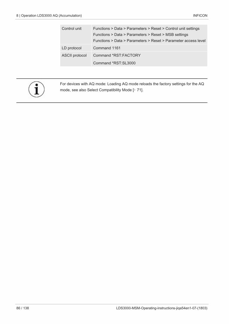
8 | Operation LDS3000 AQ (Accumulation) INFICON
86 / 138 LDS3000-MSM-Operating-instructions-jiqa54en1-07-(1803)
Control unit Functions > Data > Parameters > Reset > Control unit settingsFunctions > Data > Parameters > Reset > MSB settingsFunctions > Data > Parameters > Reset > Parameter access level
LD protocol Command 1161
ASCII protocol Command *RST:FACTORY
Command *RST:SL3000
For devices with AQ mode: Loading AQ mode reloads the factory settings for the AQmode, see also Select Compatibility Mode [} 71].
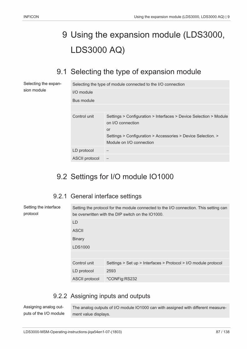
INFICON Using the expansion module (LDS3000, LDS3000 AQ) | 9
LDS3000-MSM-Operating-instructions-jiqa54en1-07-(1803) 87 / 138
9 Using the expansion module (LDS3000,LDS3000 AQ)
9.1 Selecting the type of expansion moduleSelecting the expan-sion module
Selecting the type of module connected to the I/O connection
I/O module
Bus module
Control unit Settings > Configuration > Interfaces > Device Selection > Moduleon I/O connectionorSettings > Configuration > Accessories > Device Selection. >Module on I/O connection
LD protocol –
ASCII protocol –
9.2 Settings for I/O module IO1000
9.2.1 General interface settingsSetting the interfaceprotocol
Setting the protocol for the module connected to the I/O connection. This setting canbe overwritten with the DIP switch on the IO1000.
LD
ASCII
Binary
LDS1000
Control unit Settings > Set up > Interfaces > Protocol > I/O module protocol
LD protocol 2593
ASCII protocol *CONFig:RS232
9.2.2 Assigning inputs and outputsAssigning analog out-puts of the I/O module
The analog outputs of I/O module IO1000 can with assigned with different measure-ment value displays.
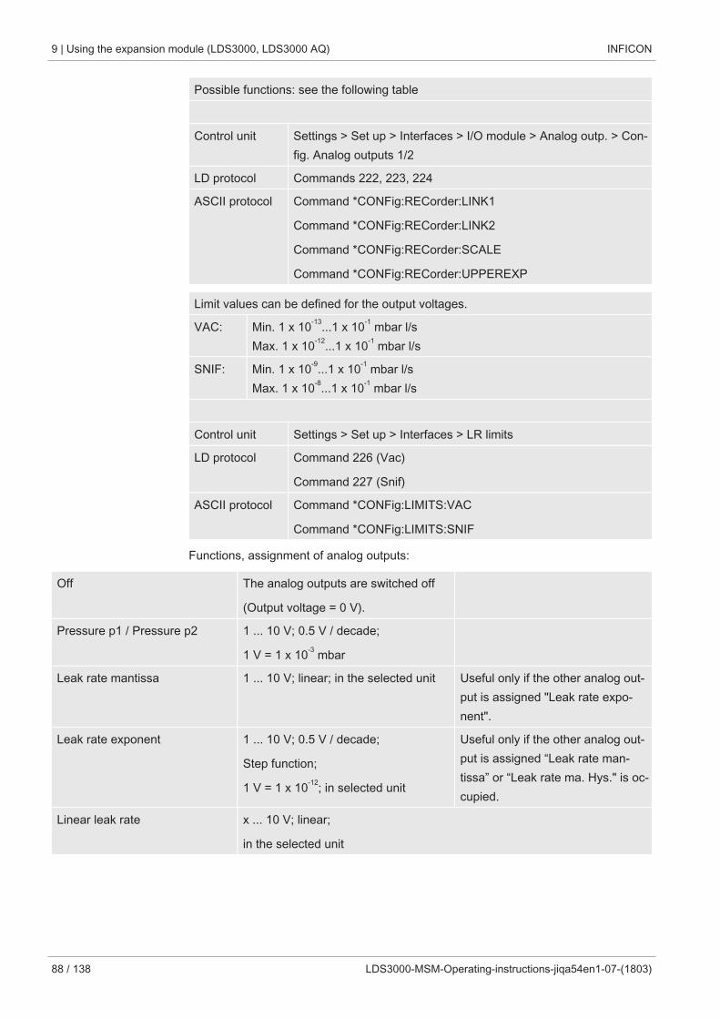
9 | Using the expansion module (LDS3000, LDS3000 AQ) INFICON
88 / 138 LDS3000-MSM-Operating-instructions-jiqa54en1-07-(1803)
Possible functions: see the following table
Control unit Settings > Set up > Interfaces > I/O module > Analog outp. > Con-fig. Analog outputs 1/2
LD protocol Commands 222, 223, 224
ASCII protocol Command *CONFig:RECorder:LINK1
Command *CONFig:RECorder:LINK2
Command *CONFig:RECorder:SCALE
Command *CONFig:RECorder:UPPEREXP
Limit values can be defined for the output voltages.
VAC: Min. 1 x 10-13...1 x 10-1 mbar l/sMax. 1 x 10-12...1 x 10-1 mbar l/s
SNIF: Min. 1 x 10⁻⁹...1 x 10-1 mbar l/sMax. 1 x 10⁻⁸...1 x 10-1 mbar l/s
Control unit Settings > Set up > Interfaces > LR limits
LD protocol Command 226 (Vac)
Command 227 (Snif)
ASCII protocol Command *CONFig:LIMITS:VAC
Command *CONFig:LIMITS:SNIF
Functions, assignment of analog outputs:
Off The analog outputs are switched off
(Output voltage = 0 V).
Pressure p1 / Pressure p2 1 ... 10 V; 0.5 V / decade;
1 V = 1 x 10⁻³ mbar
Leak rate mantissa 1 ... 10 V; linear; in the selected unit Useful only if the other analog out-put is assigned "Leak rate expo-nent".
Leak rate exponent 1 ... 10 V; 0.5 V / decade;
Step function;
1 V = 1 x 10-12; in selected unit
Useful only if the other analog out-put is assigned “Leak rate man-tissa” or “Leak rate ma. Hys." is oc-cupied.
Linear leak rate x ... 10 V; linear;
in the selected unit
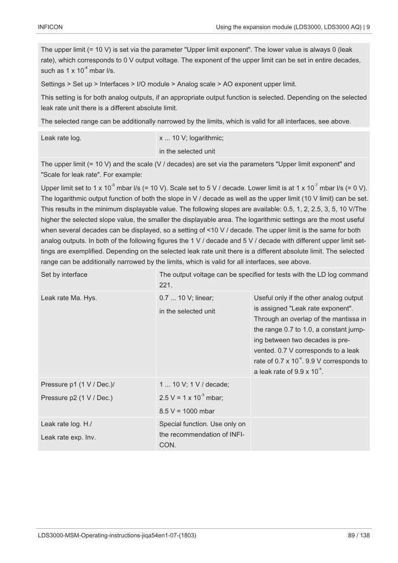
INFICON Using the expansion module (LDS3000, LDS3000 AQ) | 9
LDS3000-MSM-Operating-instructions-jiqa54en1-07-(1803) 89 / 138
The upper limit (= 10 V) is set via the parameter "Upper limit exponent". The lower value is always 0 (leakrate), which corresponds to 0 V output voltage. The exponent of the upper limit can be set in entire decades,such as 1 x 10⁻⁴ mbar l/s.
Settings > Set up > Interfaces > I/O module > Analog scale > AO exponent upper limit.
This setting is for both analog outputs, if an appropriate output function is selected. Depending on the selectedleak rate unit there is a different absolute limit.
The selected range can be additionally narrowed by the limits, which is valid for all interfaces, see above.
Leak rate log. x ... 10 V; logarithmic;
in the selected unit
The upper limit (= 10 V) and the scale (V / decades) are set via the parameters "Upper limit exponent" and"Scale for leak rate". For example:
Upper limit set to 1 x 10⁻⁵ mbar l/s (= 10 V). Scale set to 5 V / decade. Lower limit is at 1 x 10⁻⁷ mbar l/s (= 0 V).The logarithmic output function of both the slope in V / decade as well as the upper limit (10 V limit) can be set.This results in the minimum displayable value. The following slopes are available: 0.5, 1, 2, 2.5, 3, 5, 10 V/Thehigher the selected slope value, the smaller the displayable area. The logarithmic settings are the most usefulwhen several decades can be displayed, so a setting of <10 V / decade. The upper limit is the same for bothanalog outputs. In both of the following figures the 1 V / decade and 5 V / decade with different upper limit set-tings are exemplified. Depending on the selected leak rate unit there is a different absolute limit. The selectedrange can be additionally narrowed by the limits, which is valid for all interfaces, see above.
Set by interface The output voltage can be specified for tests with the LD log command221.
Leak rate Ma. Hys. 0.7 ... 10 V; linear;
in the selected unit
Useful only if the other analog outputis assigned "Leak rate exponent".Through an overlap of the mantissa inthe range 0.7 to 1.0, a constant jump-ing between two decades is pre-vented. 0.7 V corresponds to a leakrate of 0.7 x 10-x. 9.9 V corresponds toa leak rate of 9.9 x 10-x.
Pressure p1 (1 V / Dec.)/
Pressure p2 (1 V / Dec.)
1 ... 10 V; 1 V / decade;
2.5 V = 1 x 10⁻³ mbar;
8.5 V = 1000 mbar
Leak rate log. H./
Leak rate exp. Inv.
Special function. Use only onthe recommendation of INFI-CON.
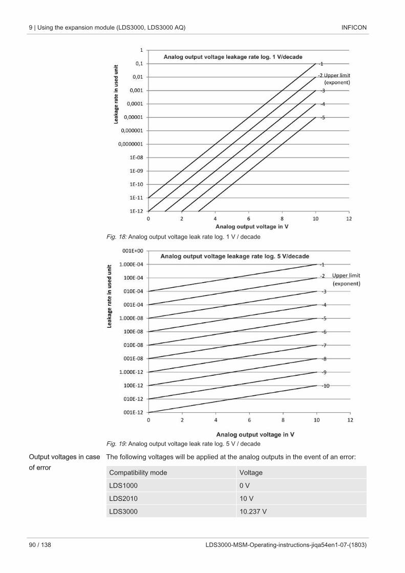
9 | Using the expansion module (LDS3000, LDS3000 AQ) INFICON
90 / 138 LDS3000-MSM-Operating-instructions-jiqa54en1-07-(1803)
Fig. 18: Analog output voltage leak rate log. 1 V / decade
Fig. 19: Analog output voltage leak rate log. 5 V / decade
Output voltages in caseof error
The following voltages will be applied at the analog outputs in the event of an error:
Compatibility mode Voltage
LDS1000 0 V
LDS2010 10 V
LDS3000 10.237 V
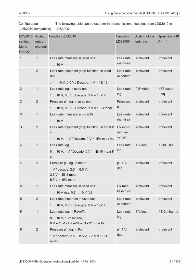
INFICON Using the expansion module (LDS3000, LDS3000 AQ) | 9
LDS3000-MSM-Operating-instructions-jiqa54en1-07-(1803) 91 / 138
Configuration(LDS2010-compatible)
The following table can be used for the transmission of settings from LDS2010 toLDS3000.
LDS2010setting.Menuitem 22
Analogoutputchannel
Function LDS2010 FunctionLDS3000
Scaling of theleak rate
Upper limit (10V = ...)
1 1 Leak rate mantissa in used unit.
1 ... 10 V
Leak ratemantissa
irrelevant irrelevant
1 2 Leak rate exponent (step function) in usedunit.
. 1 ... 10 V, 0.5 V / Decade, 1 V = 1E-12
Leak rateexponent
irrelevant irrelevant
2 1 Leak rate log. in used unit.
1 ... 10 V, 0.5 V / Decade, 1 V = 1E-12
Leak ratelog.
0.5 V/dec. 1E6 [usedunit]
2 2 Pressure p1 log. in used unit.
1 ... 10 V, 0.5 V / Decade, 1 V = 1E-3 mbar
Pressurep1
irrelevant irrelevant
3 1 Leak rate mantissa in mbar·l/s
1 ... 10 V
Leak ratemantissa
irrelevant irrelevant
3 2 Leak rate exponent (step function) in mbar·l/s
1 ... 10 V, -1 V / Decade, 0 V = 1E0 mbar l/s
LR expo-nent in-verted
irrelevant irrelevant
4 1 Leak rate log.
0 ... 10 V, 1 V / Decade, 0 V = 1E-10 mbar l/s
Leak ratelog.
1 V/dec. 1.00E+00
4 2 Pressure p1 log. in mbar
1 V / decade, 2.5 ... 8.5 V,2.5 V = 1E-3 mbar, 5.5 V = 1E0 mbar
p1 1 V/dec.
irrelevant irrelevant
5 1 Leak rate mantissa in used unit.
1 ... 10 V rise, 0.7 ... 10 V fall
LR man-tissa hyst.
irrelevant irrelevant
5 2 Leak rate exponent in used unit.
1 ... 10 V, 0.5 V / Decade, 0 V = 1E-14
Leak rateexponent
irrelevant irrelevant
6 1 Leak rate log. in Pa·m³/s
0 ... 10 V, 1 V/Decade, 0 V = 1E-12 Pa·m³/s = 1E-12 mbar l/s
Leak ratelog.
1 V/dec. 1E-2 mbar l/s
6 2 Pressure p1 log. in Pa
1 V / decade, 2.5 ... 8.5 V, 2.5 V = 1E-3mbar
p1 1 V/dec.
irrelevant irrelevant
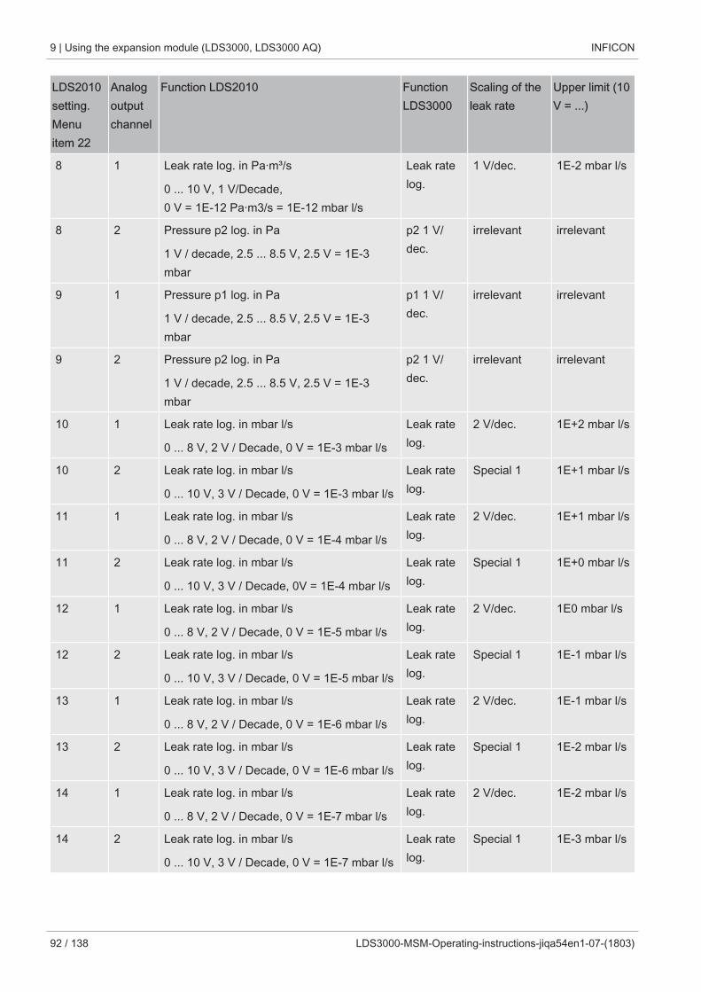
9 | Using the expansion module (LDS3000, LDS3000 AQ) INFICON
92 / 138 LDS3000-MSM-Operating-instructions-jiqa54en1-07-(1803)
LDS2010setting.Menuitem 22
Analogoutputchannel
Function LDS2010 FunctionLDS3000
Scaling of theleak rate
Upper limit (10V = ...)
8 1 Leak rate log. in Pa·m³/s
0 ... 10 V, 1 V/Decade, 0 V = 1E-12 Pa·m3/s = 1E-12 mbar l/s
Leak ratelog.
1 V/dec. 1E-2 mbar l/s
8 2 Pressure p2 log. in Pa
1 V / decade, 2.5 ... 8.5 V, 2.5 V = 1E-3mbar
p2 1 V/dec.
irrelevant irrelevant
9 1 Pressure p1 log. in Pa
1 V / decade, 2.5 ... 8.5 V, 2.5 V = 1E-3mbar
p1 1 V/dec.
irrelevant irrelevant
9 2 Pressure p2 log. in Pa
1 V / decade, 2.5 ... 8.5 V, 2.5 V = 1E-3mbar
p2 1 V/dec.
irrelevant irrelevant
10 1 Leak rate log. in mbar l/s
0 ... 8 V, 2 V / Decade, 0 V = 1E-3 mbar l/s
Leak ratelog.
2 V/dec. 1E+2 mbar l/s
10 2 Leak rate log. in mbar l/s
0 ... 10 V, 3 V / Decade, 0 V = 1E-3 mbar l/s
Leak ratelog.
Special 1 1E+1 mbar l/s
11 1 Leak rate log. in mbar l/s
0 ... 8 V, 2 V / Decade, 0 V = 1E-4 mbar l/s
Leak ratelog.
2 V/dec. 1E+1 mbar l/s
11 2 Leak rate log. in mbar l/s
0 ... 10 V, 3 V / Decade, 0V = 1E-4 mbar l/s
Leak ratelog.
Special 1 1E+0 mbar l/s
12 1 Leak rate log. in mbar l/s
0 ... 8 V, 2 V / Decade, 0 V = 1E-5 mbar l/s
Leak ratelog.
2 V/dec. 1E0 mbar l/s
12 2 Leak rate log. in mbar l/s
0 ... 10 V, 3 V / Decade, 0 V = 1E-5 mbar l/s
Leak ratelog.
Special 1 1E-1 mbar l/s
13 1 Leak rate log. in mbar l/s
0 ... 8 V, 2 V / Decade, 0 V = 1E-6 mbar l/s
Leak ratelog.
2 V/dec. 1E-1 mbar l/s
13 2 Leak rate log. in mbar l/s
0 ... 10 V, 3 V / Decade, 0 V = 1E-6 mbar l/s
Leak ratelog.
Special 1 1E-2 mbar l/s
14 1 Leak rate log. in mbar l/s
0 ... 8 V, 2 V / Decade, 0 V = 1E-7 mbar l/s
Leak ratelog.
2 V/dec. 1E-2 mbar l/s
14 2 Leak rate log. in mbar l/s
0 ... 10 V, 3 V / Decade, 0 V = 1E-7 mbar l/s
Leak ratelog.
Special 1 1E-3 mbar l/s
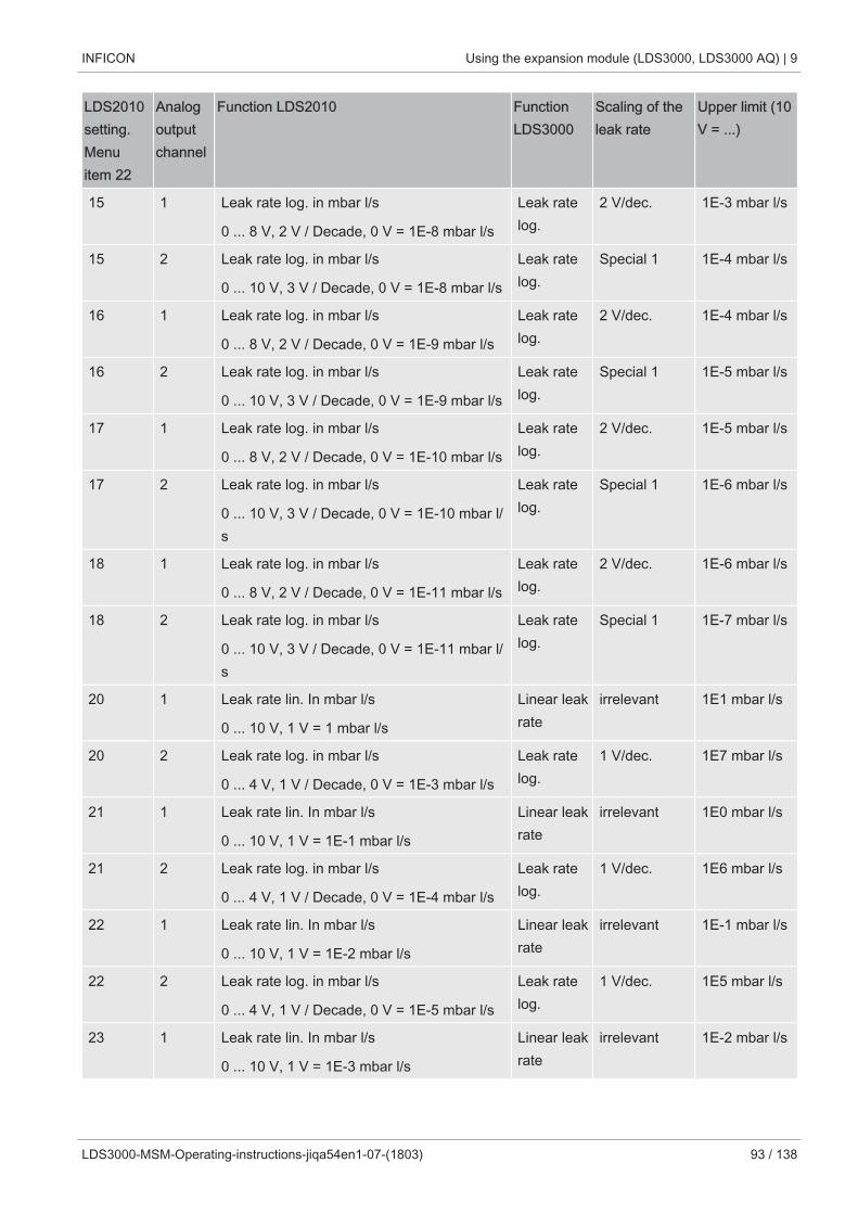
INFICON Using the expansion module (LDS3000, LDS3000 AQ) | 9
LDS3000-MSM-Operating-instructions-jiqa54en1-07-(1803) 93 / 138
LDS2010setting.Menuitem 22
Analogoutputchannel
Function LDS2010 FunctionLDS3000
Scaling of theleak rate
Upper limit (10V = ...)
15 1 Leak rate log. in mbar l/s
0 ... 8 V, 2 V / Decade, 0 V = 1E-8 mbar l/s
Leak ratelog.
2 V/dec. 1E-3 mbar l/s
15 2 Leak rate log. in mbar l/s
0 ... 10 V, 3 V / Decade, 0 V = 1E-8 mbar l/s
Leak ratelog.
Special 1 1E-4 mbar l/s
16 1 Leak rate log. in mbar l/s
0 ... 8 V, 2 V / Decade, 0 V = 1E-9 mbar l/s
Leak ratelog.
2 V/dec. 1E-4 mbar l/s
16 2 Leak rate log. in mbar l/s
0 ... 10 V, 3 V / Decade, 0 V = 1E-9 mbar l/s
Leak ratelog.
Special 1 1E-5 mbar l/s
17 1 Leak rate log. in mbar l/s
0 ... 8 V, 2 V / Decade, 0 V = 1E-10 mbar l/s
Leak ratelog.
2 V/dec. 1E-5 mbar l/s
17 2 Leak rate log. in mbar l/s
0 ... 10 V, 3 V / Decade, 0 V = 1E-10 mbar l/s
Leak ratelog.
Special 1 1E-6 mbar l/s
18 1 Leak rate log. in mbar l/s
0 ... 8 V, 2 V / Decade, 0 V = 1E-11 mbar l/s
Leak ratelog.
2 V/dec. 1E-6 mbar l/s
18 2 Leak rate log. in mbar l/s
0 ... 10 V, 3 V / Decade, 0 V = 1E-11 mbar l/s
Leak ratelog.
Special 1 1E-7 mbar l/s
20 1 Leak rate lin. In mbar l/s
0 ... 10 V, 1 V = 1 mbar l/s
Linear leakrate
irrelevant 1E1 mbar l/s
20 2 Leak rate log. in mbar l/s
0 ... 4 V, 1 V / Decade, 0 V = 1E-3 mbar l/s
Leak ratelog.
1 V/dec. 1E7 mbar l/s
21 1 Leak rate lin. In mbar l/s
0 ... 10 V, 1 V = 1E-1 mbar l/s
Linear leakrate
irrelevant 1E0 mbar l/s
21 2 Leak rate log. in mbar l/s
0 ... 4 V, 1 V / Decade, 0 V = 1E-4 mbar l/s
Leak ratelog.
1 V/dec. 1E6 mbar l/s
22 1 Leak rate lin. In mbar l/s
0 ... 10 V, 1 V = 1E-2 mbar l/s
Linear leakrate
irrelevant 1E-1 mbar l/s
22 2 Leak rate log. in mbar l/s
0 ... 4 V, 1 V / Decade, 0 V = 1E-5 mbar l/s
Leak ratelog.
1 V/dec. 1E5 mbar l/s
23 1 Leak rate lin. In mbar l/s
0 ... 10 V, 1 V = 1E-3 mbar l/s
Linear leakrate
irrelevant 1E-2 mbar l/s
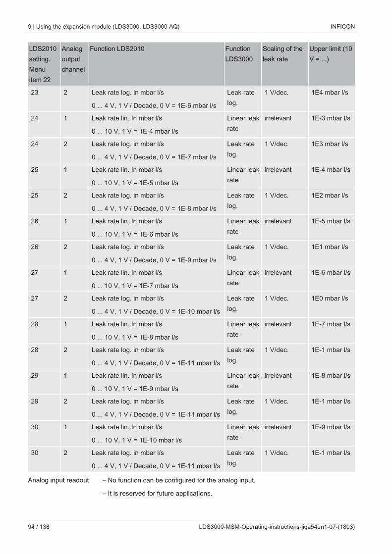
9 | Using the expansion module (LDS3000, LDS3000 AQ) INFICON
94 / 138 LDS3000-MSM-Operating-instructions-jiqa54en1-07-(1803)
LDS2010setting.Menuitem 22
Analogoutputchannel
Function LDS2010 FunctionLDS3000
Scaling of theleak rate
Upper limit (10V = ...)
23 2 Leak rate log. in mbar l/s
0 ... 4 V, 1 V / Decade, 0 V = 1E-6 mbar l/s
Leak ratelog.
1 V/dec. 1E4 mbar l/s
24 1 Leak rate lin. In mbar l/s
0 ... 10 V, 1 V = 1E-4 mbar l/s
Linear leakrate
irrelevant 1E-3 mbar l/s
24 2 Leak rate log. in mbar l/s
0 ... 4 V, 1 V / Decade, 0 V = 1E-7 mbar l/s
Leak ratelog.
1 V/dec. 1E3 mbar l/s
25 1 Leak rate lin. In mbar l/s
0 ... 10 V, 1 V = 1E-5 mbar l/s
Linear leakrate
irrelevant 1E-4 mbar l/s
25 2 Leak rate log. in mbar l/s
0 ... 4 V, 1 V / Decade, 0 V = 1E-8 mbar l/s
Leak ratelog.
1 V/dec. 1E2 mbar l/s
26 1 Leak rate lin. In mbar l/s
0 ... 10 V, 1 V = 1E-6 mbar l/s
Linear leakrate
irrelevant 1E-5 mbar l/s
26 2 Leak rate log. in mbar l/s
0 ... 4 V, 1 V / Decade, 0 V = 1E-9 mbar l/s
Leak ratelog.
1 V/dec. 1E1 mbar l/s
27 1 Leak rate lin. In mbar l/s
0 ... 10 V, 1 V = 1E-7 mbar l/s
Linear leakrate
irrelevant 1E-6 mbar l/s
27 2 Leak rate log. in mbar l/s
0 ... 4 V, 1 V / Decade, 0 V = 1E-10 mbar l/s
Leak ratelog.
1 V/dec. 1E0 mbar l/s
28 1 Leak rate lin. In mbar l/s
0 ... 10 V, 1 V = 1E-8 mbar l/s
Linear leakrate
irrelevant 1E-7 mbar l/s
28 2 Leak rate log. in mbar l/s
0 ... 4 V, 1 V / Decade, 0 V = 1E-11 mbar l/s
Leak ratelog.
1 V/dec. 1E-1 mbar l/s
29 1 Leak rate lin. In mbar l/s
0 ... 10 V, 1 V = 1E-9 mbar l/s
Linear leakrate
irrelevant 1E-8 mbar l/s
29 2 Leak rate log. in mbar l/s
0 ... 4 V, 1 V / Decade, 0 V = 1E-11 mbar l/s
Leak ratelog.
1 V/dec. 1E-1 mbar l/s
30 1 Leak rate lin. In mbar l/s
0 ... 10 V, 1 V = 1E-10 mbar l/s
Linear leakrate
irrelevant 1E-9 mbar l/s
30 2 Leak rate log. in mbar l/s
0 ... 4 V, 1 V / Decade, 0 V = 1E-11 mbar l/s
Leak ratelog.
1 V/dec. 1E-1 mbar l/s
Analog input readout – No function can be configured for the analog input.
– It is reserved for future applications.
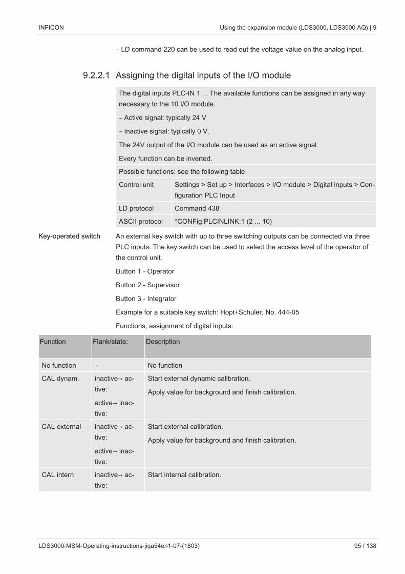
INFICON Using the expansion module (LDS3000, LDS3000 AQ) | 9
LDS3000-MSM-Operating-instructions-jiqa54en1-07-(1803) 95 / 138
– LD command 220 can be used to read out the voltage value on the analog input.
9.2.2.1 Assigning the digital inputs of the I/O module
The digital inputs PLC-IN 1 ... The available functions can be assigned in any waynecessary to the 10 I/O module.
– Active signal: typically 24 V
– Inactive signal: typically 0 V.
The 24V output of the I/O module can be used as an active signal.
Every function can be inverted.
Possible functions: see the following table
Control unit Settings > Set up > Interfaces > I/O module > Digital inputs > Con-figuration PLC Input
LD protocol Command 438
ASCII protocol *CONFig:PLCINLINK:1 (2 ... 10)
Key-operated switch An external key switch with up to three switching outputs can be connected via threePLC inputs. The key switch can be used to select the access level of the operator ofthe control unit.
Button 1 - Operator
Button 2 - Supervisor
Button 3 - Integrator
Example for a suitable key switch: Hopt+Schuler, No. 444-05
Functions, assignment of digital inputs:
Function Flank/state: Description
No function – No function
CAL dynam. inactive→ ac-tive:
active→ inac-tive:
Start external dynamic calibration.
Apply value for background and finish calibration.
CAL external inactive→ ac-tive:
active→ inac-tive:
Start external calibration.
Apply value for background and finish calibration.
CAL intern inactive→ ac-tive:
Start internal calibration.
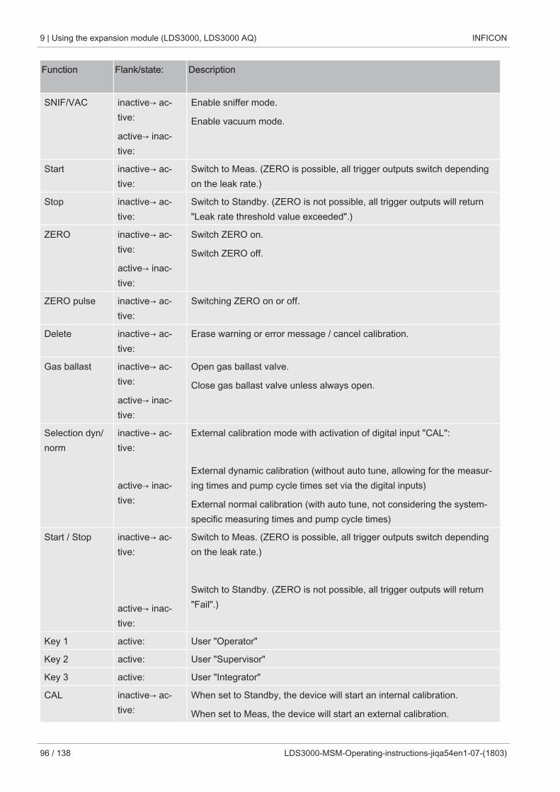
9 | Using the expansion module (LDS3000, LDS3000 AQ) INFICON
96 / 138 LDS3000-MSM-Operating-instructions-jiqa54en1-07-(1803)
Function Flank/state: Description
SNIF/VAC inactive→ ac-tive:
active→ inac-tive:
Enable sniffer mode.
Enable vacuum mode.
Start inactive→ ac-tive:
Switch to Meas. (ZERO is possible, all trigger outputs switch dependingon the leak rate.)
Stop inactive→ ac-tive:
Switch to Standby. (ZERO is not possible, all trigger outputs will return"Leak rate threshold value exceeded".)
ZERO inactive→ ac-tive:
active→ inac-tive:
Switch ZERO on.
Switch ZERO off.
ZERO pulse inactive→ ac-tive:
Switching ZERO on or off.
Delete inactive→ ac-tive:
Erase warning or error message / cancel calibration.
Gas ballast inactive→ ac-tive:
active→ inac-tive:
Open gas ballast valve.
Close gas ballast valve unless always open.
Selection dyn/norm
inactive→ ac-tive:
active→ inac-tive:
External calibration mode with activation of digital input "CAL":
External dynamic calibration (without auto tune, allowing for the measur-ing times and pump cycle times set via the digital inputs)
External normal calibration (with auto tune, not considering the system-specific measuring times and pump cycle times)
Start / Stop inactive→ ac-tive:
active→ inac-tive:
Switch to Meas. (ZERO is possible, all trigger outputs switch dependingon the leak rate.)
Switch to Standby. (ZERO is not possible, all trigger outputs will return"Fail".)
Key 1 active: User "Operator"
Key 2 active: User "Supervisor"
Key 3 active: User "Integrator"
CAL inactive→ ac-tive:
When set to Standby, the device will start an internal calibration.
When set to Meas, the device will start an external calibration.
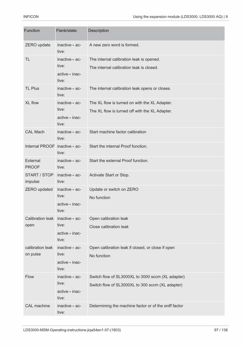
INFICON Using the expansion module (LDS3000, LDS3000 AQ) | 9
LDS3000-MSM-Operating-instructions-jiqa54en1-07-(1803) 97 / 138
Function Flank/state: Description
ZERO update inactive→ ac-tive:
A new zero word is formed.
TL inactive→ ac-tive:
active→ inac-tive:
The internal calibration leak is opened.
The internal calibration leak is closed.
TL Plus inactive→ ac-tive:
The internal calibration leak opens or closes.
XL flow inactive→ ac-tive:
active→ inac-tive:
The XL flow is turned on with the XL Adapter.
The XL flow is turned off with the XL Adapter.
CAL Mach inactive→ ac-tive:
Start machine factor calibration
Internal PROOF inactive→ ac-tive:
Start the internal Proof function.
ExternalPROOF
inactive→ ac-tive:
Start the external Proof function.
START / STOPimpulse
inactive→ ac-tive:
Activate Start or Stop.
ZERO updated inactive→ ac-tive:
active→ inac-tive:
Update or switch on ZERO
No function
Calibration leakopen
inactive→ ac-tive:
active→ inac-tive:
Open calibration leak
Close calibration leak
calibration leakon pulse
inactive→ ac-tive:
active→ inac-tive:
Open calibration leak if closed, or close if open
No function
Flow inactive→ ac-tive:
active→ inac-tive:
Switch flow of SL3000XL to 3000 sccm (XL adapter)
Switch flow of SL3000XL to 300 sccm (XL adapter)
CAL machine inactive→ ac-tive:
Determining the machine factor or of the sniff factor
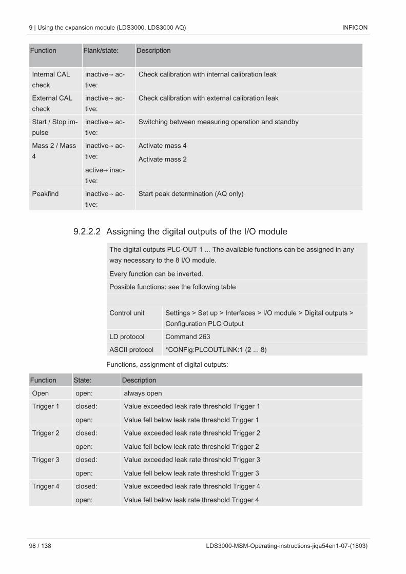
9 | Using the expansion module (LDS3000, LDS3000 AQ) INFICON
98 / 138 LDS3000-MSM-Operating-instructions-jiqa54en1-07-(1803)
Function Flank/state: Description
Internal CALcheck
inactive→ ac-tive:
Check calibration with internal calibration leak
External CALcheck
inactive→ ac-tive:
Check calibration with external calibration leak
Start / Stop im-pulse
inactive→ ac-tive:
Switching between measuring operation and standby
Mass 2 / Mass4
inactive→ ac-tive:
active→ inac-tive:
Activate mass 4
Activate mass 2
Peakfind inactive→ ac-tive:
Start peak determination (AQ only)
9.2.2.2 Assigning the digital outputs of the I/O module
The digital outputs PLC-OUT 1 ... The available functions can be assigned in anyway necessary to the 8 I/O module.
Every function can be inverted.
Possible functions: see the following table
Control unit Settings > Set up > Interfaces > I/O module > Digital outputs >Configuration PLC Output
LD protocol Command 263
ASCII protocol *CONFig:PLCOUTLINK:1 (2 ... 8)
Functions, assignment of digital outputs:
Function State: Description
Open open: always open
Trigger 1 closed:
open:
Value exceeded leak rate threshold Trigger 1
Value fell below leak rate threshold Trigger 1
Trigger 2 closed:
open:
Value exceeded leak rate threshold Trigger 2
Value fell below leak rate threshold Trigger 2
Trigger 3 closed:
open:
Value exceeded leak rate threshold Trigger 3
Value fell below leak rate threshold Trigger 3
Trigger 4 closed:
open:
Value exceeded leak rate threshold Trigger 4
Value fell below leak rate threshold Trigger 4
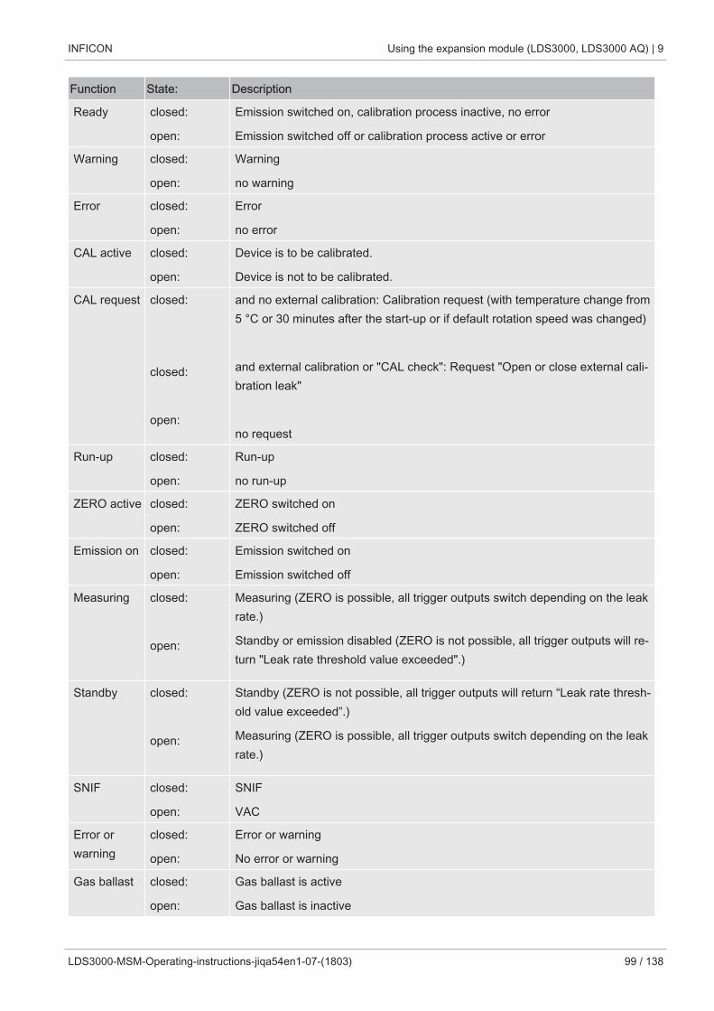
INFICON Using the expansion module (LDS3000, LDS3000 AQ) | 9
LDS3000-MSM-Operating-instructions-jiqa54en1-07-(1803) 99 / 138
Function State: Description
Ready closed:
open:
Emission switched on, calibration process inactive, no error
Emission switched off or calibration process active or error
Warning closed:
open:
Warning
no warning
Error closed:
open:
Error
no error
CAL active closed:
open:
Device is to be calibrated.
Device is not to be calibrated.
CAL request closed:
closed:
open:
and no external calibration: Calibration request (with temperature change from5 °C or 30 minutes after the start-up or if default rotation speed was changed)
and external calibration or "CAL check": Request "Open or close external cali-bration leak"
no request
Run-up closed:
open:
Run-up
no run-up
ZERO active closed:
open:
ZERO switched on
ZERO switched off
Emission on closed:
open:
Emission switched on
Emission switched off
Measuring closed:
open:
Measuring (ZERO is possible, all trigger outputs switch depending on the leakrate.)
Standby or emission disabled (ZERO is not possible, all trigger outputs will re-turn "Leak rate threshold value exceeded".)
Standby closed:
open:
Standby (ZERO is not possible, all trigger outputs will return “Leak rate thresh-old value exceeded”.)
Measuring (ZERO is possible, all trigger outputs switch depending on the leakrate.)
SNIF closed:
open:
SNIF
VAC
Error orwarning
closed:
open:
Error or warning
No error or warning
Gas ballast closed:
open:
Gas ballast is active
Gas ballast is inactive
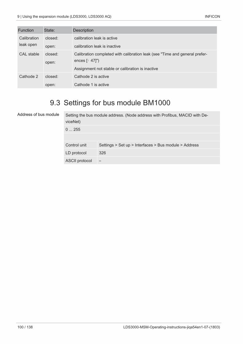
9 | Using the expansion module (LDS3000, LDS3000 AQ) INFICON
100 / 138 LDS3000-MSM-Operating-instructions-jiqa54en1-07-(1803)
Function State: Description
Calibrationleak open
closed:
open:
calibration leak is active
calibration leak is inactive
CAL stable closed:
open:
Calibration completed with calibration leak (see "Time and general prefer-ences [} 47]")
Assignment not stable or calibration is inactive
Cathode 2 closed:
open:
Cathode 2 is active
Cathode 1 is active
9.3 Settings for bus module BM1000Address of bus module Setting the bus module address. (Node address with Profibus, MACID with De-
viceNet)
0 ... 255
Control unit Settings > Set up > Interfaces > Bus module > Address
LD protocol 326
ASCII protocol –
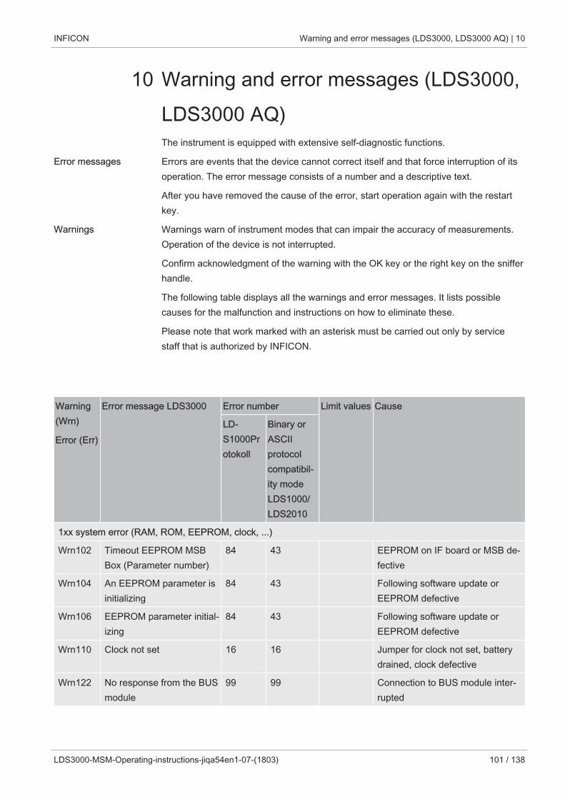
INFICON Warning and error messages (LDS3000, LDS3000 AQ) | 10
LDS3000-MSM-Operating-instructions-jiqa54en1-07-(1803) 101 / 138
10 Warning and error messages (LDS3000,LDS3000 AQ)The instrument is equipped with extensive self-diagnostic functions.
Error messages Errors are events that the device cannot correct itself and that force interruption of itsoperation. The error message consists of a number and a descriptive text.
After you have removed the cause of the error, start operation again with the restartkey.
Warnings Warnings warn of instrument modes that can impair the accuracy of measurements.Operation of the device is not interrupted.
Confirm acknowledgment of the warning with the OK key or the right key on the snifferhandle.
The following table displays all the warnings and error messages. It lists possiblecauses for the malfunction and instructions on how to eliminate these.
Please note that work marked with an asterisk must be carried out only by servicestaff that is authorized by INFICON.
Warning(Wrn)
Error (Err)
Error message LDS3000 Error number Limit values Cause
LD-S1000Protokoll
Binary orASCIIprotocolcompatibil-ity modeLDS1000/LDS2010
1xx system error (RAM, ROM, EEPROM, clock, ...)
Wrn102 Timeout EEPROM MSBBox (Parameter number)
84 43 EEPROM on IF board or MSB de-fective
Wrn104 An EEPROM parameter isinitializing
84 43 Following software update orEEPROM defective
Wrn106 EEPROM parameter initial-izing
84 43 Following software update orEEPROM defective
Wrn110 Clock not set 16 16 Jumper for clock not set, batterydrained, clock defective
Wrn122 No response from the BUSmodule
99 99 Connection to BUS module inter-rupted
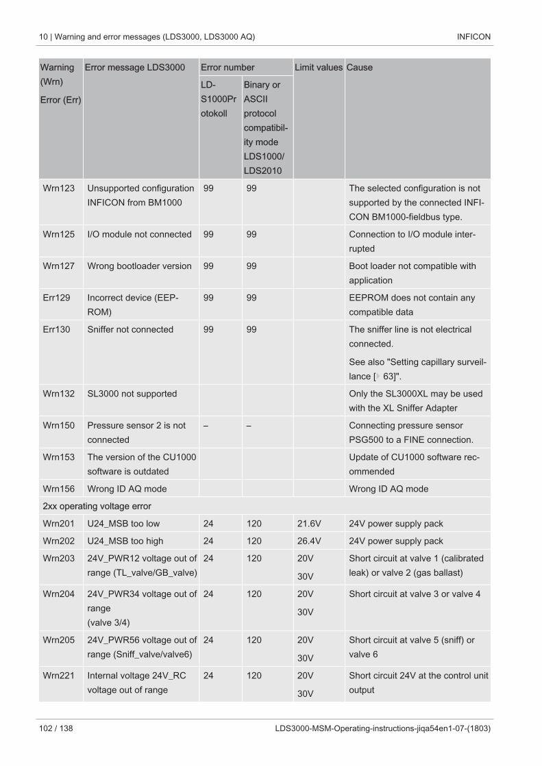
10 | Warning and error messages (LDS3000, LDS3000 AQ) INFICON
102 / 138 LDS3000-MSM-Operating-instructions-jiqa54en1-07-(1803)
Warning(Wrn)
Error (Err)
Error message LDS3000 Error number Limit values Cause
LD-S1000Protokoll
Binary orASCIIprotocolcompatibil-ity modeLDS1000/LDS2010
Wrn123 Unsupported configurationINFICON from BM1000
99 99 The selected configuration is notsupported by the connected INFI-CON BM1000-fieldbus type.
Wrn125 I/O module not connected 99 99 Connection to I/O module inter-rupted
Wrn127 Wrong bootloader version 99 99 Boot loader not compatible withapplication
Err129 Incorrect device (EEP-ROM)
99 99 EEPROM does not contain anycompatible data
Err130 Sniffer not connected 99 99 The sniffer line is not electricalconnected.
See also "Setting capillary surveil-lance [} 63]".
Wrn132 SL3000 not supported Only the SL3000XL may be usedwith the XL Sniffer Adapter
Wrn150 Pressure sensor 2 is notconnected
– – Connecting pressure sensorPSG500 to a FINE connection.
Wrn153 The version of the CU1000software is outdated
Update of CU1000 software rec-ommended
Wrn156 Wrong ID AQ mode Wrong ID AQ mode
2xx operating voltage error
Wrn201 U24_MSB too low 24 120 21.6V 24V power supply pack
Wrn202 U24_MSB too high 24 120 26.4V 24V power supply pack
Wrn203 24V_PWR12 voltage out ofrange (TL_valve/GB_valve)
24 120 20V
30V
Short circuit at valve 1 (calibratedleak) or valve 2 (gas ballast)
Wrn204 24V_PWR34 voltage out ofrange (valve 3/4)
24 120 20V
30V
Short circuit at valve 3 or valve 4
Wrn205 24V_PWR56 voltage out ofrange (Sniff_valve/valve6)
24 120 20V
30V
Short circuit at valve 5 (sniff) orvalve 6
Wrn221 Internal voltage 24V_RCvoltage out of range
24 120 20V
30V
Short circuit 24V at the control unitoutput
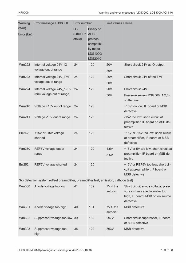
INFICON Warning and error messages (LDS3000, LDS3000 AQ) | 10
LDS3000-MSM-Operating-instructions-jiqa54en1-07-(1803) 103 / 138
Warning(Wrn)
Error (Err)
Error message LDS3000 Error number Limit values Cause
LD-S1000Protokoll
Binary orASCIIprotocolcompatibil-ity modeLDS1000/LDS2010
Wrn222 Internal voltage 24V_IOvoltage out of range
24 120 20V
30V
Short circuit 24V at IO output
Wrn223 Internal voltage 24V_TMPvoltage out of range
24 120 20V
30V
Short circuit 24V of the TMP
Wrn224 Internal voltage 24V_1 (Pi-rani) voltage out of range
24 120 20V
30V
Short circuit 24V
Pressure sensor PSG500 (1,2,3),sniffer line
Wrn240 Voltage +15V out of range 24 120 +15V too low, IF board or MSBdefective
Wrn241 Voltage -15V out of range 24 120 -15V too low, short circuit atpreamplifier, IF board or MSB de-fective
Err242 +15V or -15V voltageshorted
24 120 +15V or -15V too low, short circuitat preamplifier, IF board or MSBdefective
Wrn250 REF5V voltage out ofrange
24 120 4.5V
5.5V
+15V or 5V too low, short circuit atpreamplifier, IF board or MSB de-fective
Err252 REF5V voltage shorted 24 120 +15V or REF5V too low, short cir-cuit at preamplifier, IF board orMSB defective
3xx detection system (offset preamplifier, preamplifier test, emission, cathode test)
Wrn300 Anode voltage too low 41 132 7V < thesetpoint
Short circuit anode voltage, pres-sure in mass spectrometer toohigh, IF board, MSB or ion sourcedefective
Wrn301 Anode voltage too high 40 131 7V > thesetpoint
MSB defective
Wrn302 Suppressor voltage too low 39 130 297V Short circuit suppressor, IF boardor MSB defective
Wrn303 Suppressor voltage toohigh
38 129 363V MSB defective
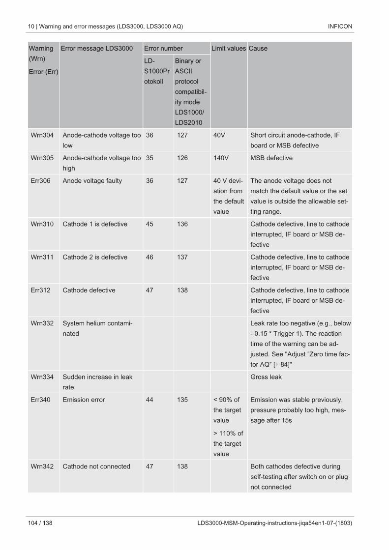
10 | Warning and error messages (LDS3000, LDS3000 AQ) INFICON
104 / 138 LDS3000-MSM-Operating-instructions-jiqa54en1-07-(1803)
Warning(Wrn)
Error (Err)
Error message LDS3000 Error number Limit values Cause
LD-S1000Protokoll
Binary orASCIIprotocolcompatibil-ity modeLDS1000/LDS2010
Wrn304 Anode-cathode voltage toolow
36 127 40V Short circuit anode-cathode, IFboard or MSB defective
Wrn305 Anode-cathode voltage toohigh
35 126 140V MSB defective
Err306 Anode voltage faulty 36 127 40 V devi-ation fromthe defaultvalue
The anode voltage does notmatch the default value or the setvalue is outside the allowable set-ting range.
Wrn310 Cathode 1 is defective 45 136 Cathode defective, line to cathodeinterrupted, IF board or MSB de-fective
Wrn311 Cathode 2 is defective 46 137 Cathode defective, line to cathodeinterrupted, IF board or MSB de-fective
Err312 Cathode defective 47 138 Cathode defective, line to cathodeinterrupted, IF board or MSB de-fective
Wrn332 System helium contami-nated
Leak rate too negative (e.g., below- 0.15 * Trigger 1). The reactiontime of the warning can be ad-justed. See "Adjust ”Zero time fac-tor AQ” [} 84]"
Wrn334 Sudden increase in leakrate
Gross leak
Err340 Emission error 44 135 < 90% ofthe targetvalue
> 110% ofthe targetvalue
Emission was stable previously,pressure probably too high, mes-sage after 15s
Wrn342 Cathode not connected 47 138 Both cathodes defective duringself-testing after switch on or plugnot connected
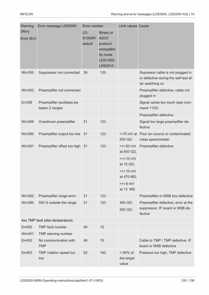
INFICON Warning and error messages (LDS3000, LDS3000 AQ) | 10
LDS3000-MSM-Operating-instructions-jiqa54en1-07-(1803) 105 / 138
Warning(Wrn)
Error (Err)
Error message LDS3000 Error number Limit values Cause
LD-S1000Protokoll
Binary orASCIIprotocolcompatibil-ity modeLDS1000/LDS2010
Wrn350 Suppressor not connected 39 130 Supressor cable is not plugged inor defective during the self-test af-ter switching on
Wrn352 Preamplifier not connected Preamplifier defective, cable notplugged in
Err358 Preamplifier oscillates be-tween 2 ranges
Signal varies too much (see com-mand 1120)
Preamplifier defective
Wrn359 Overdriven preamplifier 31 123 Signal too large preamplifier de-fective
Wrn360 Preamplifier output too low 31 123 <-70 mV at500 GΩ
Poor ion source or contaminatedmass spectrometer
Wrn361 Preamplifier offset too high 31 123 >+/-50 mVat 500 GΩ,
>+/-10 mVat 15 GΩ,
<+/-10 mVat 470 MΩ,
<+/-9 mVat 13 MΩ
Preamplifier defective
Wrn362 Preamplifier range error 31 123 Preamplifier or MSB box defective
Wrn390 500 G outside the range 31 123 450 GΩ
550 GΩ
Preamplifier defective, error at thesuppressor, IF board or MSB de-fective
4xx TMP fault (also temperature)
Err400 TMP fault number 49 15
Wrn401 TMP warning number
Err402 No communication withTMP
49 15 Cable to TMP / TMP defective, IFboard or MSB defective
Err403 TMP rotation speed toolow
53 142 < 95% ofthe targetvalue
Pressure too high, TMP defective
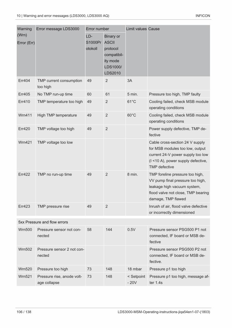
10 | Warning and error messages (LDS3000, LDS3000 AQ) INFICON
106 / 138 LDS3000-MSM-Operating-instructions-jiqa54en1-07-(1803)
Warning(Wrn)
Error (Err)
Error message LDS3000 Error number Limit values Cause
LD-S1000Protokoll
Binary orASCIIprotocolcompatibil-ity modeLDS1000/LDS2010
Err404 TMP current consumptiontoo high
49 2 3A
Err405 No TMP run-up time 60 61 5 min. Pressure too high, TMP faulty
Err410 TMP temperature too high 49 2 61°C Cooling failed, check MSB moduleoperating conditions
Wrn411 High TMP temperature 49 2 60°C Cooling failed, check MSB moduleoperating conditions
Err420 TMP voltage too high 49 2 Power supply defective, TMP de-fective
Wrn421 TMP voltage too low Cable cross-section 24 V supplyfor MSB modules too low, outputcurrent 24-V power supply too low(I <10 A), power supply defective,TMP defective
Err422 TMP no run-up time 49 2 8 min. TMP foreline pressure too high,VV pump final pressure too high,leakage high vacuum system,flood valve not close, TMP bearingdamage, TMP flawed
Err423 TMP pressure rise 49 2 Inrush of air, flood valve defectiveor incorrectly dimensioned
5xx Pressure and flow errors
Wrn500 Pressure sensor not con-nected
58 144 0.5V Pressure sensor PSG500 P1 notconnected, IF board or MSB de-fective
Wrn502 Pressure sensor 2 not con-nected
Pressure sensor PSG500 P2 notconnected, IF board or MSB de-fective.
Wrn520 Pressure too high 73 148 18 mbar Pressure p1 too high
Wrn521 Pressure rise, anode volt-age collapse
73 148 < Setpoint- 20V
Pressure p1 too high, message af-ter 1.4s
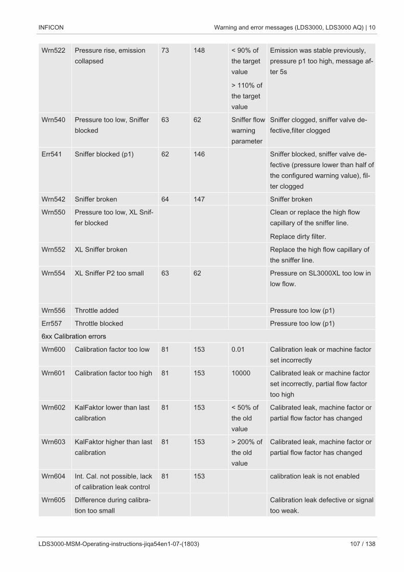
INFICON Warning and error messages (LDS3000, LDS3000 AQ) | 10
LDS3000-MSM-Operating-instructions-jiqa54en1-07-(1803) 107 / 138
Wrn522 Pressure rise, emissioncollapsed
73 148 < 90% ofthe targetvalue
> 110% ofthe targetvalue
Emission was stable previously,pressure p1 too high, message af-ter 5s
Wrn540 Pressure too low, Snifferblocked
63 62 Sniffer flowwarningparameter
Sniffer clogged, sniffer valve de-fective,filter clogged
Err541 Sniffer blocked (p1) 62 146 Sniffer blocked, sniffer valve de-fective (pressure lower than half ofthe configured warning value), fil-ter clogged
Wrn542 Sniffer broken 64 147 Sniffer broken
Wrn550 Pressure too low, XL Snif-fer blocked
Clean or replace the high flowcapillary of the sniffer line.
Replace dirty filter.
Wrn552 XL Sniffer broken Replace the high flow capillary ofthe sniffer line.
Wrn554 XL Sniffer P2 too small 63 62 Pressure on SL3000XL too low inlow flow.
Wrn556 Throttle added Pressure too low (p1)
Err557 Throttle blocked Pressure too low (p1)
6xx Calibration errors
Wrn600 Calibration factor too low 81 153 0.01 Calibration leak or machine factorset incorrectly
Wrn601 Calibration factor too high 81 153 10000 Calibrated leak or machine factorset incorrectly, partial flow factortoo high
Wrn602 KalFaktor lower than lastcalibration
81 153 < 50% ofthe oldvalue
Calibrated leak, machine factor orpartial flow factor has changed
Wrn603 KalFaktor higher than lastcalibration
81 153 > 200% ofthe oldvalue
Calibrated leak, machine factor orpartial flow factor has changed
Wrn604 Int. Cal. not possible, lackof calibration leak control
81 153 calibration leak is not enabled
Wrn605 Difference during calibra-tion too small
Calibration leak defective or signaltoo weak.
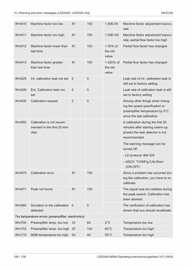
10 | Warning and error messages (LDS3000, LDS3000 AQ) INFICON
108 / 138 LDS3000-MSM-Operating-instructions-jiqa54en1-07-(1803)
Wrn610 Machine factor too low 81 153 1.00E-04 Machine factor adjustment inaccu-rate
Wrn611 Machine factor too high 81 153 1.00E+04 Machine factor adjustment inaccu-rate, partial flow factor too high
Wrn612 Machine factor lower thanlast time
81 153 < 50% ofthe oldvalue
Partial flow factor has changed
Wrn613 Machine factor greaterthan last time
81 153 > 200% ofthe oldvalue
Partial flow factor has changed
Wrn625 Int. calibration leak not set 0 0 Leak rate of int. calibration leak isstill set to factory setting
Wrn626 Ext. Calibration leak notset
0 0 Leak rate of calibration leak is stillset to factory setting
Wrn630 Calibration request 0 0 Among other things when chang-ing the speed specification orpreamplifier temperature by 5°Csince the last calibration
Wrn650 Calibration is not recom-mended in the first 20 min-utes
A calibration during the first 20minutes after starting (warm-upphase) the leak detector is notrecommended.
The warning message can beturned off:
- LD protocol: Bef 429
– ASCII: *CONFig:CALWarn (ON,OFF)
Wrn670 Calibration error 81 153 Since a problem has occurred dur-ing the calibration, you have to re-calibrate.
Wrn671 Peak not found 81 153 The signal was too restless duringthe peak search. Calibration hasbeen aborted.
Wrn680 Deviation to the calibrationdetected
0 0 The verification of calibration hasshown that you should recalibrate.
7xx temperature errors (preamplifier, electronics)
Wrn700 Preamplifier temp. too low 33 60 2°C Temperature too low
Wrn702 Preamplifier temp. too high 32 124 60°C Temperature too high
Wrn710 MSB temperature too high 54 44 55°C Temperature too high
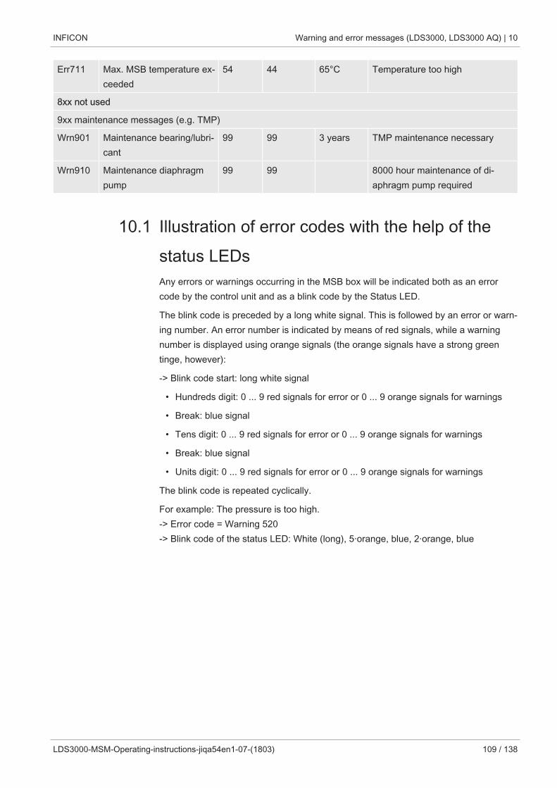
INFICON Warning and error messages (LDS3000, LDS3000 AQ) | 10
LDS3000-MSM-Operating-instructions-jiqa54en1-07-(1803) 109 / 138
Err711 Max. MSB temperature ex-ceeded
54 44 65°C Temperature too high
8xx not used
9xx maintenance messages (e.g. TMP)
Wrn901 Maintenance bearing/lubri-cant
99 99 3 years TMP maintenance necessary
Wrn910 Maintenance diaphragmpump
99 99 8000 hour maintenance of di-aphragm pump required
10.1 Illustration of error codes with the help of thestatus LEDsAny errors or warnings occurring in the MSB box will be indicated both as an errorcode by the control unit and as a blink code by the Status LED.
The blink code is preceded by a long white signal. This is followed by an error or warn-ing number. An error number is indicated by means of red signals, while a warningnumber is displayed using orange signals (the orange signals have a strong greentinge, however):
-> Blink code start: long white signal
• Hundreds digit: 0 ... 9 red signals for error or 0 ... 9 orange signals for warnings
• Break: blue signal
• Tens digit: 0 ... 9 red signals for error or 0 ... 9 orange signals for warnings
• Break: blue signal
• Units digit: 0 ... 9 red signals for error or 0 ... 9 orange signals for warnings
The blink code is repeated cyclically.
For example: The pressure is too high.-> Error code = Warning 520-> Blink code of the status LED: White (long), 5·orange, blue, 2·orange, blue
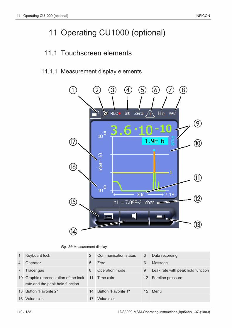
11 | Operating CU1000 (optional) INFICON
110 / 138 LDS3000-MSM-Operating-instructions-jiqa54en1-07-(1803)
11 Operating CU1000 (optional)
11.1 Touchscreen elements
11.1.1 Measurement display elements
Fig. 20: Measurement display
1 Keyboard lock 2 Communication status 3 Data recording
4 Operator 5 Zero 6 Message
7 Tracer gas 8 Operation mode 9 Leak rate with peak hold function
10 Graphic representation of the leakrate and the peak hold function
11 Time axis 12 Foreline pressure
13 Button "Favorite 2" 14 Button "Favorite 1" 15 Menu
16 Value axis 17 Value axis
INFICON Operating CU1000 (optional) | 11
LDS3000-MSM-Operating-instructions-jiqa54en1-07-(1803) 111 / 138
1 - Keyboard lock
The control unit is locked or unlocked by pressing and holding the icon for the key-board lock.
2 - Icon for the communication status
• Icon connected: The device communicates with the mass spectrometer module.
• Icon disconnected: The device does not communicate with the mass spectrometermodule.
Establish communication:
1 Reset control unit.
2 Checking the status of the mass spectrometer module.
3 Check cable connection.
3 - Icon for the data recording
The measurement is recorded.
4 - Ser
The registered operator is shown abbreviated.
Display Meaning
Ope Operator
Sup Supervisor
Int Integrator
Ser Service
For more information, see Chapter 6.2.2., Page 20.
5 - Zero
Background suppression is active.
6 - Caution icon
Active warnings are stored in the unit.
The active warnings can be displayed via the menu "Info > History > Warnings".
7 - Tracer gas
Set tracer gas and tracer gas concentration percentage.
Display Meaning
He Helium (4He)
H2 Hydrogen
11 | Operating CU1000 (optional) INFICON
112 / 138 LDS3000-MSM-Operating-instructions-jiqa54en1-07-(1803)
Display Meaning
M3 E.g. H-D, 3He or H3
8 - Operation mode
Configured operation mode
Display Operation mode
VA Vacuum
SNIF Sniff
LOW FLOW XL sniffer adapter in LOW FLOW
HIGH FLOW XL sniffer adapter in HIGH FLOW
Standby XL sniffer adapter in HIGH FLOW onstandby
9 - Leak rate
Current measurement for the leak rate.
10 - Graph
Graphic display of the leak rate Q(t).
11 - Leak rate
Time axis of the leak rate Q(t).
12 - Primary vacuum pressure (not with operation mode XL SnifferAdapter)
Backing pressure p1.
13 - Button "Favorite 2"
You can assign preferred parameters to this button (see Page 19 ). In Fig. 4 the button"Favorite 2" is assigned the function "Start/Stop" for example.
14 - Button "Favorite 1"
You can assign preferred parameters to this button (see Page 19 ). In Fig. 4 the button"Favorite 1" is assigned the function "ZERO" for example.
15 - Icon for the menu
All functions and parameters of the control unit can be accessed using the "Menu"key .
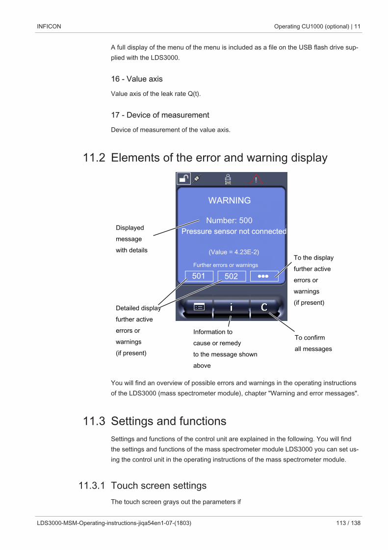
INFICON Operating CU1000 (optional) | 11
LDS3000-MSM-Operating-instructions-jiqa54en1-07-(1803) 113 / 138
A full display of the menu of the menu is included as a file on the USB flash drive sup-plied with the LDS3000.
16 - Value axis
Value axis of the leak rate Q(t).
17 - Device of measurement
Device of measurement of the value axis.
11.2 Elements of the error and warning display
Displayedmessagewith details
Detailed displayfurther activeerrors orwarnings(if present)
To the displayfurther activeerrors orwarnings(if present)
WARNING
Number: 500Pressure sensor not connected
(Value = 4.23E-2)
Further errors or warnings
To confirmall messages
Information tocause or remedyto the message shownabove
501 502
You will find an overview of possible errors and warnings in the operating instructionsof the LDS3000 (mass spectrometer module), chapter "Warning and error messages".
11.3 Settings and functionsSettings and functions of the control unit are explained in the following. You will findthe settings and functions of the mass spectrometer module LDS3000 you can set us-ing the control unit in the operating instructions of the mass spectrometer module.
11.3.1 Touch screen settingsThe touch screen grays out the parameters if
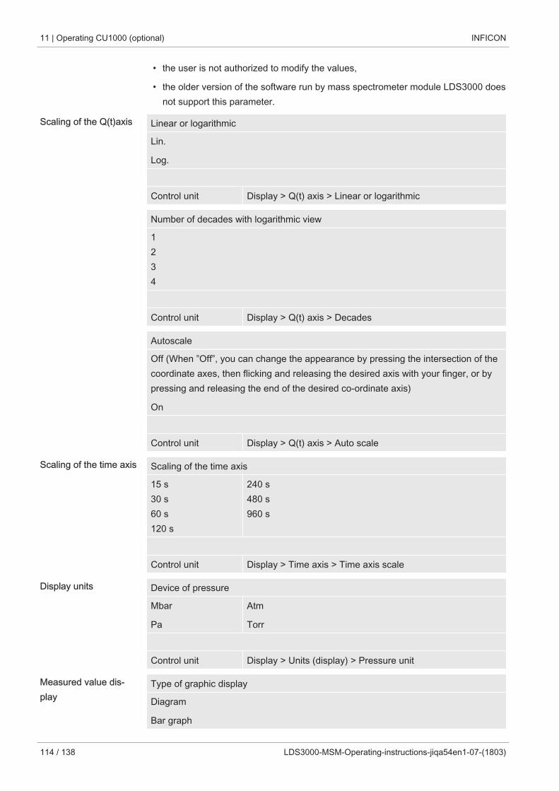
11 | Operating CU1000 (optional) INFICON
114 / 138 LDS3000-MSM-Operating-instructions-jiqa54en1-07-(1803)
• the user is not authorized to modify the values,
• the older version of the software run by mass spectrometer module LDS3000 doesnot support this parameter.
Scaling of the Q(t)axis Linear or logarithmic
Lin.
Log.
Control unit Display > Q(t) axis > Linear or logarithmic
Number of decades with logarithmic view
1234
Control unit Display > Q(t) axis > Decades
Autoscale
Off (When ”Off”, you can change the appearance by pressing the intersection of thecoordinate axes, then flicking and releasing the desired axis with your finger, or bypressing and releasing the end of the desired co-ordinate axis)
On
Control unit Display > Q(t) axis > Auto scale
Scaling of the time axis Scaling of the time axis
15 s30 s60 s120 s
240 s480 s960 s
Control unit Display > Time axis > Time axis scale
Display units Device of pressure
Mbar
Pa
Atm
Torr
Control unit Display > Units (display) > Pressure unit
Measured value dis-play
Type of graphic display
Diagram
Bar graph
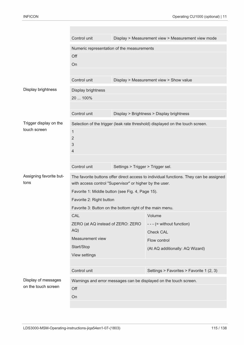
INFICON Operating CU1000 (optional) | 11
LDS3000-MSM-Operating-instructions-jiqa54en1-07-(1803) 115 / 138
Control unit Display > Measurement view > Measurement view mode
Numeric representation of the measurements
Off
On
Control unit Display > Measurement view > Show value
Display brightness Display brightness
20 ... 100%
Control unit Display > Brightness > Display brightness
Trigger display on thetouch screen
Selection of the trigger (leak rate threshold) displayed on the touch screen.
1234
Control unit Settings > Trigger > Trigger sel.
Assigning favorite but-tons
The favorite buttons offer direct access to individual functions. They can be assignedwith access control "Supervisor" or higher by the user.
Favorite 1: Middle button (see Fig. 4, Page 15).
Favorite 2: Right button
Favorite 3: Button on the bottom right of the main menu.
CAL
ZERO (at AQ instead of ZERO: ZEROAQ)
Measurement view
Start/Stop
View settings
Volume
- - - (= without function)
Check CAL
Flow control
(At AQ additionally: AQ Wizard)
Control unit Settings > Favorites > Favorite 1 (2, 3)
Display of messageson the touch screen
Warnings and error messages can be displayed on the touch screen.
Off
On
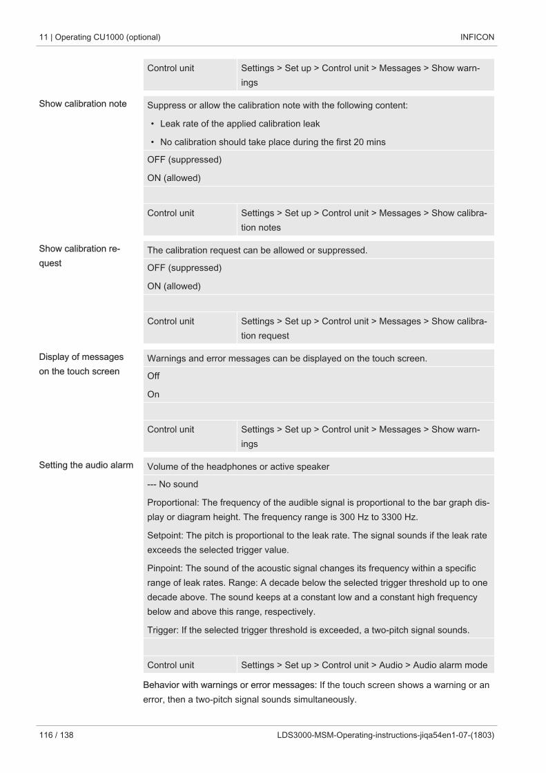
11 | Operating CU1000 (optional) INFICON
116 / 138 LDS3000-MSM-Operating-instructions-jiqa54en1-07-(1803)
Control unit Settings > Set up > Control unit > Messages > Show warn-ings
Show calibration note Suppress or allow the calibration note with the following content:
• Leak rate of the applied calibration leak
• No calibration should take place during the first 20 mins
OFF (suppressed)
ON (allowed)
Control unit Settings > Set up > Control unit > Messages > Show calibra-tion notes
Show calibration re-quest
The calibration request can be allowed or suppressed.
OFF (suppressed)
ON (allowed)
Control unit Settings > Set up > Control unit > Messages > Show calibra-tion request
Display of messageson the touch screen
Warnings and error messages can be displayed on the touch screen.
Off
On
Control unit Settings > Set up > Control unit > Messages > Show warn-ings
Setting the audio alarm Volume of the headphones or active speaker
--- No sound
Proportional: The frequency of the audible signal is proportional to the bar graph dis-play or diagram height. The frequency range is 300 Hz to 3300 Hz.
Setpoint: The pitch is proportional to the leak rate. The signal sounds if the leak rateexceeds the selected trigger value.
Pinpoint: The sound of the acoustic signal changes its frequency within a specificrange of leak rates. Range: A decade below the selected trigger threshold up to onedecade above. The sound keeps at a constant low and a constant high frequencybelow and above this range, respectively.
Trigger: If the selected trigger threshold is exceeded, a two-pitch signal sounds.
Control unit Settings > Set up > Control unit > Audio > Audio alarm mode
Behavior with warnings or error messages: If the touch screen shows a warning or anerror, then a two-pitch signal sounds simultaneously.
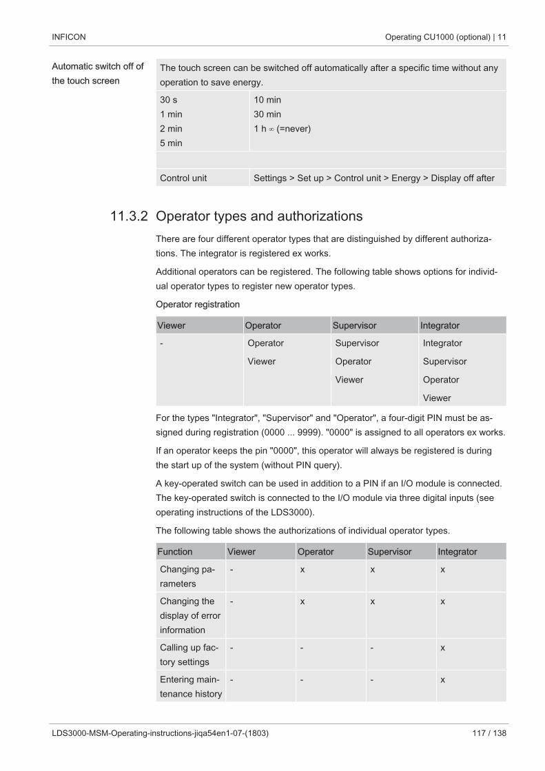
INFICON Operating CU1000 (optional) | 11
LDS3000-MSM-Operating-instructions-jiqa54en1-07-(1803) 117 / 138
Automatic switch off ofthe touch screen
The touch screen can be switched off automatically after a specific time without anyoperation to save energy.
30 s1 min2 min5 min
10 min30 min1 h ∞ (=never)
Control unit Settings > Set up > Control unit > Energy > Display off after
11.3.2 Operator types and authorizationsThere are four different operator types that are distinguished by different authoriza-tions. The integrator is registered ex works.
Additional operators can be registered. The following table shows options for individ-ual operator types to register new operator types.
Operator registration
Viewer Operator Supervisor Integrator
- Operator
Viewer
Supervisor
Operator
Viewer
Integrator
Supervisor
Operator
Viewer
For the types "Integrator", "Supervisor" and "Operator", a four-digit PIN must be as-signed during registration (0000 ... 9999). "0000" is assigned to all operators ex works.
If an operator keeps the pin "0000", this operator will always be registered is duringthe start up of the system (without PIN query).
A key-operated switch can be used in addition to a PIN if an I/O module is connected.The key-operated switch is connected to the I/O module via three digital inputs (seeoperating instructions of the LDS3000).
The following table shows the authorizations of individual operator types.
Function Viewer Operator Supervisor Integrator
Changing pa-rameters
- x x x
Changing thedisplay of errorinformation
- x x x
Calling up fac-tory settings
- - - x
Entering main-tenance history
- - - x
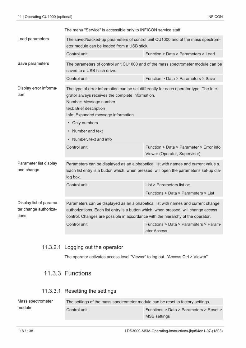
11 | Operating CU1000 (optional) INFICON
118 / 138 LDS3000-MSM-Operating-instructions-jiqa54en1-07-(1803)
The menu "Service" is accessible only to INFICON service staff.
Load parameters The saved/backed-up parameters of control unit CU1000 and of the mass spectrom-eter module can be loaded from a USB stick.
Control unit Function > Data > Parameters > Load
Save parameters The parameters of control unit CU1000 and of the mass spectrometer module can besaved to a USB flash drive.
Control unit Function > Data > Parameters > Save
Display error informa-tion
The type of error information can be set differently for each operator type. The Inte-grator always receives the complete information.Number: Message numbertext: Brief descriptionInfo: Expanded message information
• Only numbers
• Number and text
• Number, text and info
Control unit Function > Data > Parameter > Error infoViewer (Operator, Supervisor)
Parameter list displayand change
Parameters can be displayed as an alphabetical list with names and current value s.Each list entry is a button which, when pressed, will open the parameter's set-up dia-log box.
Control unit List > Parameters list or:
Functions > Data > Parameters > List
Display list of parame-ter change authoriza-tions
Parameters can be displayed as an alphabetical list with names and current changeauthorizations. Each list entry is a button which, when pressed, will change accesscontrol. Changes are possible in accordance with the hierarchy of the operator.
Control unit Functions > Data > Parameters > Param-eter Access
11.3.2.1 Logging out the operatorThe operator activates access level "Viewer" to log out. "Access Ctrl > Viewer"
11.3.3 Functions
11.3.3.1 Resetting the settings
Mass spectrometermodule
The settings of the mass spectrometer module can be reset to factory settings.
Control unit Functions > Data > Parameters > Reset >MSB settings
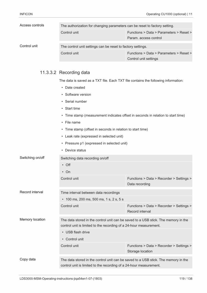
INFICON Operating CU1000 (optional) | 11
LDS3000-MSM-Operating-instructions-jiqa54en1-07-(1803) 119 / 138
Access controls The authorization for changing parameters can be reset to factory setting.
Control unit Functions > Data > Parameters > Reset >Param. access control
Control unit The control unit settings can be reset to factory settings.
Control unit Functions > Data > Parameters > Reset >Control unit settings
11.3.3.2 Recording dataThe data is saved as a TXT file. Each TXT file contains the following information:
• Date created
• Software version
• Serial number
• Start time
• Time stamp (measurement indicates offset in seconds in relation to start time)
• File name
• Time stamp (offset in seconds in relation to start time)
• Leak rate (expressed in selected unit)
• Pressure p1 (expressed in selected unit)
• Device status
Switching on/off Switching data recording on/off
• Off
• On
Control unit Functions > Data > Recorder > Settings >Data recording
Record interval Time interval between data recordings
• 100 ms, 200 ms, 500 ms, 1 s, 2 s, 5 s
Control unit Functions > Data > Recorder > Settings >Record interval
Memory location The data stored in the control unit can be saved to a USB stick. The memory in thecontrol unit is limited to the recording of a 24-hour measurement.
• USB flash drive
• Control unit
Control unit Functions > Data > Recorder > Settings >Storage location
Copy data The data stored in the control unit can be saved to a USB stick. The memory in thecontrol unit is limited to the recording of a 24-hour measurement.
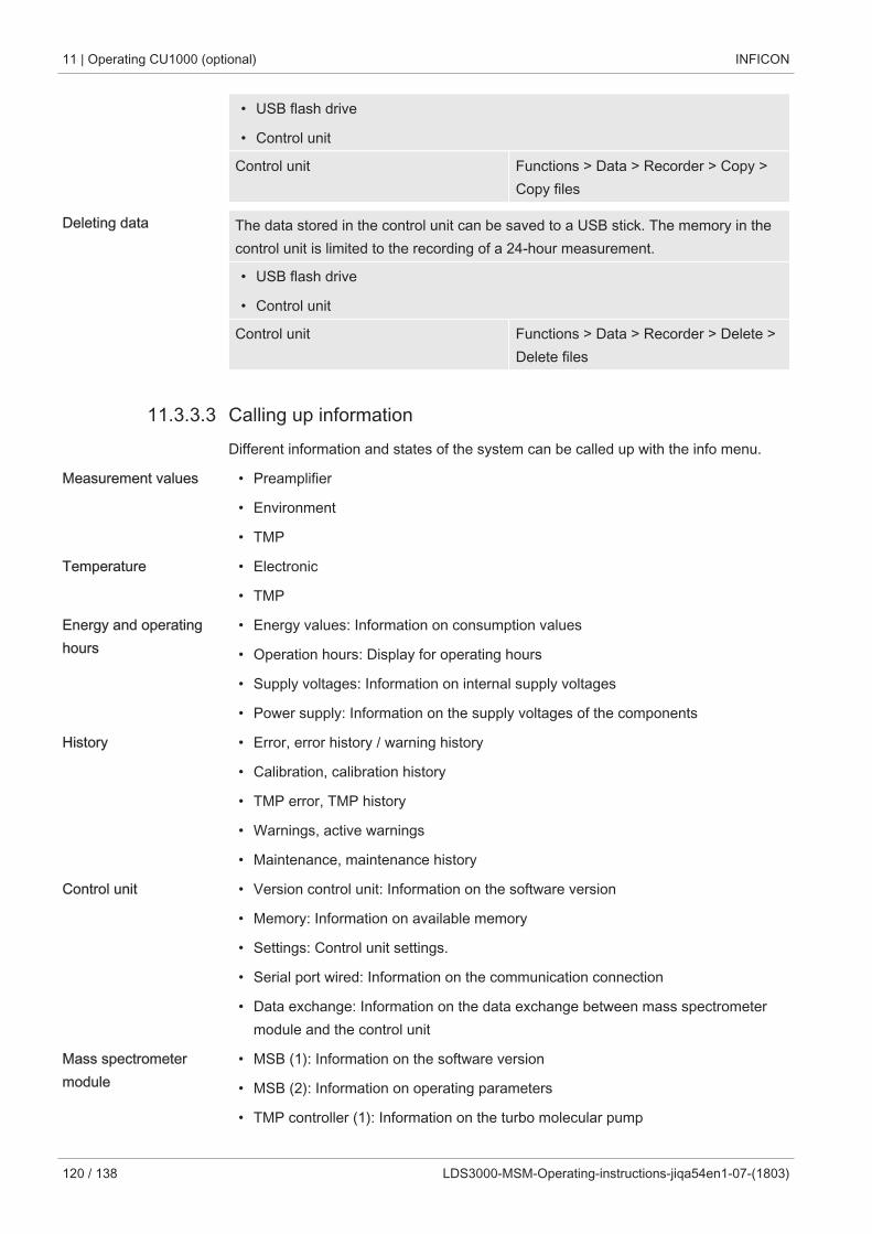
11 | Operating CU1000 (optional) INFICON
120 / 138 LDS3000-MSM-Operating-instructions-jiqa54en1-07-(1803)
• USB flash drive
• Control unit
Control unit Functions > Data > Recorder > Copy >Copy files
Deleting data The data stored in the control unit can be saved to a USB stick. The memory in thecontrol unit is limited to the recording of a 24-hour measurement.
• USB flash drive
• Control unit
Control unit Functions > Data > Recorder > Delete >Delete files
11.3.3.3 Calling up informationDifferent information and states of the system can be called up with the info menu.
Measurement values • Preamplifier
• Environment
• TMP
Temperature • Electronic
• TMP
Energy and operatinghours
• Energy values: Information on consumption values
• Operation hours: Display for operating hours
• Supply voltages: Information on internal supply voltages
• Power supply: Information on the supply voltages of the components
History • Error, error history / warning history
• Calibration, calibration history
• TMP error, TMP history
• Warnings, active warnings
• Maintenance, maintenance history
Control unit • Version control unit: Information on the software version
• Memory: Information on available memory
• Settings: Control unit settings.
• Serial port wired: Information on the communication connection
• Data exchange: Information on the data exchange between mass spectrometermodule and the control unit
Mass spectrometermodule
• MSB (1): Information on the software version
• MSB (2): Information on operating parameters
• TMP controller (1): Information on the turbo molecular pump
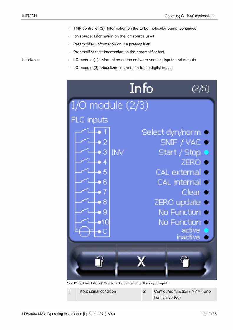
INFICON Operating CU1000 (optional) | 11
LDS3000-MSM-Operating-instructions-jiqa54en1-07-(1803) 121 / 138
• TMP controller (2): Information on the turbo molecular pump, continued
• Ion source: Information on the ion source used
• Preamplifier: Information on the preamplifier
• Preamplifier test: Information on the preamplifier test.
Interfaces • I/O module (1): Information on the software version, inputs and outputs
• I/O module (2): Visualized information to the digital inputs
Fig. 21: I/O module (2): Visualized information to the digital inputs
1 Input signal condition 2 Configured function (INV = Func-tion is inverted)
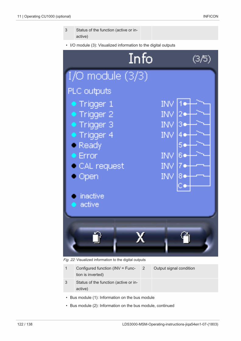
11 | Operating CU1000 (optional) INFICON
122 / 138 LDS3000-MSM-Operating-instructions-jiqa54en1-07-(1803)
3 Status of the function (active or in-active)
• I/O module (3): Visualized information to the digital outputs
Fig. 22: Visualized information to the digital outputs
1 Configured function (INV = Func-tion is inverted)
2 Output signal condition
3 Status of the function (active or in-active)
• Bus module (1): Information on the bus module
• Bus module (2): Information on the bus module, continued
INFICON Operating CU1000 (optional) | 11
LDS3000-MSM-Operating-instructions-jiqa54en1-07-(1803) 123 / 138
11.3.4 Updating the softwareSoftware updates from INFICON are installed with the aid of a USB flash drive. Theupdate function of the device can be found under "Functions > Data > Update".
An update is possible,
• if one or several updates are available on the USB flash drive, but only one updateper type at most (control unit, MSB box, I/O module),
• if these parts are also connected free of disturbances and have an update func-tion.
The corresponding buttons in the update menu such as "Control Unit", "MSB Box",and "I/O Module" are active and can be activated individually.
NOTICE
Aborted connection
Data loss due to an aborted connection
► Do not switch off the device and do not remove the USB flash drive while the soft-ware is being updated!
► Switch the device off and back on after a software update has taken place.
11.3.4.1 Updating the software of the control unitThe software is included in two files named Handset_IFC_Vx.xx.xx.exe and Hand-set_IFC_Vx.xx.xx.key.
1 Copy the file into the main directory of a USB flash drive.
2 Connect the USB flash drive to the USB port on the device.
3 Select: "Functions > Data > Update > Control unit".
ð Do not switch off the device and do not remove the USB flash drive while thesoftware is being updated!
4 Check the version information.
5 Select the "Start" button to start the update. Do not switch off the device and donot remove the USB flash drive while the software is being updated!
6 Follow the instructions on the touchscreen and wait until the update is complete.
11.3.4.2 Checking and updating the software version of the MSB boxThe current software is available from the Inficon support.
The functions of the XL Sniffer adapter set are taken into consideration in system soft-ware version 2.11 or higher.
11 | Operating CU1000 (optional) INFICON
124 / 138 LDS3000-MSM-Operating-instructions-jiqa54en1-07-(1803)
1 Copy the file Flash_LDS3000_MSB_Vxx.xx.xxx.bin into the main directory of aUSB flash drive.
2 Connect the USB flash drive to the USB port on the device.
3 Select: "Functions > Data > Update > MSB".
ð The display shows information on the current and the new software versionas well as on the boot loader.
4 Check the version information.
ð Select the "Start" button to start the update.
ð Do not switch off the device and do not remove the USB flash drive while thesoftware is being updated! Do not switch off the device and do not removethe USB flash drive while the software is being updated!
5 Follow the instructions on the touchscreen and wait until the update is complete.
6 If the system displays warning 104 or 106, confirm with "C".
11.3.4.3 Updating the software of the I/O moduleThe software of the I/O module can be updated from the control unit if the mass spec-trometer module has the software version "MS module 1.02" or higher.
1 Copy the file Flash_LDS3000_IO_Vxx.xx.xxx.bin into the main directory of aUSB flash drive.
2 Connect the USB flash drive to the USB port on the device.
3 Select: "Functions > Data > Update > I/O module"
ð The display shows information on the current and the new software as well ason the current boot loader.
4 Check the version information.
5 Select the "Start" button to start the update.
ð Do not switch off the device and do not remove the USB flash drive while thesoftware is being updated!
6 Follow the instructions on the touchscreen and wait until the update is complete.
ð The following tips are shown after selecting the "Start" button on the touch-screen:
• Connect and switch on the IO1000.
• Activate boot mode (switch DIP S2.3 on and off once).
• When the STATUS LED flashes green, press OK.
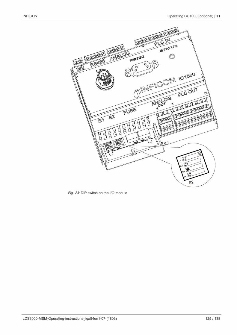
INFICON Operating CU1000 (optional) | 11
LDS3000-MSM-Operating-instructions-jiqa54en1-07-(1803) 125 / 138
Fig. 23: DIP switch on the I/O module
12 | Maintenance INFICON
126 / 138 LDS3000-MSM-Operating-instructions-jiqa54en1-07-(1803)
12 MaintenanceThe mass spectrometer module is a leak testing unit that is intended for industrial ap-plications. The device is composed of parts and assemblies that are, for the most part,low maintenance.
Servicing the mass spectrometer module merely requires that you change the operat-ing fluid reservoir of the turbo molecular pump and check the fan on the turbo molecu-lar pump.
We recommend that you sign a service agreement with INFICON or one of INFICON'sauthorized service partners.
12.1 Maintenance at INFICON
WARNING
Danger to health
Contaminated devices could endanger the health of INFICON employees.
► Fill in the declaration of contamination completely.
► Attach the declaration of contamination to the outside of the packaging.
The declaration of contamination is a legal requirement and serves to protect our em-ployees. INFICON sends devices which are sent without a completed declaration ofcontamination back to the sender. See "Declaration of Contamination [} 136]".
12.2 General maintenance informationThe maintenance work that needs to be performed on the mass spectrometer moduleis grouped into three service levels:
• Service level I: Customer without any technical training
• Service level II: Customer with technical and INFICON training
• Service level III: INFICON Service
DANGER
Life threatening hazard from electric shock
High voltages are inside the device. Touching parts where electrical voltage is presentcan result in death.
► Disconnect the device from the power supply prior to any maintenance work.
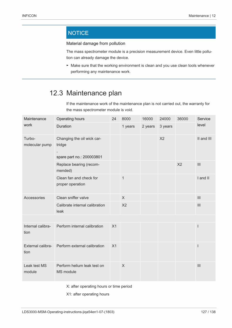
INFICON Maintenance | 12
LDS3000-MSM-Operating-instructions-jiqa54en1-07-(1803) 127 / 138
NOTICE
Material damage from pollution
The mass spectrometer module is a precision measurement device. Even little pollu-tion can already damage the device.
► Make sure that the working environment is clean and you use clean tools wheneverperforming any maintenance work.
12.3 Maintenance planIf the maintenance work of the maintenance plan is not carried out, the warranty forthe mass spectrometer module is void.
Maintenancework
Operating hours 24 8000 16000 24000 36000 ServicelevelDuration 1 years 2 years 3 years
Turbo-molecular pump
Changing the oil wick car-tridge, spare part no.: 200003801
X2 II and III
Replace bearing (recom-mended)
X2 III
Clean fan and check forproper operation
1 I and II
Accessories Clean sniffer valve X III
Calibrate internal calibrationleak
X2 III
Internal calibra-tion
Perform internal calibration X1 I
External calibra-tion
Perform external calibration X1 I
Leak test MSmodule
Perform helium leak test onMS module
X III
X: after operating hours or time period
X1: after operating hours
12 | Maintenance INFICON
128 / 138 LDS3000-MSM-Operating-instructions-jiqa54en1-07-(1803)
X2: by duration
1: depending on environment and use
12.4 Maintenance work
12.4.1 Change operating fluid reservoir of turbo molecular pumpThe turbo molecular pump is filled with an operating fluid for the lubrication of the ballbearings. The operating fluid reservoir must be replaced every 2 years at the latest.With extreme strain of the pump or in unclean processes, the lubricant reservoir mustbe replaced at shorter intervals.
The cover of the operating fluid reservoir can be unscrewed only when the turbomolecular pump is flooded.
Flood the turbo molecular pump
1 Shut down mass spectrometer module, see "Decommissioning the measuringinstrument [} 133]".
2 Wait until turbo molecular pump is drained (at least 1 min).
3 Disconnect 24 V power supply pack from MSB box.
4 Allow the turbo molecular pump to cool down if necessary.
5 Remove turbo molecular pump.
6 Open the ventilation screw slowly.
ð Turbo molecular pump is flooded until it reaches atmospheric pressure.
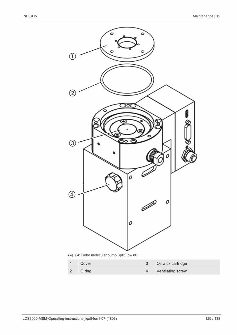
INFICON Maintenance | 12
LDS3000-MSM-Operating-instructions-jiqa54en1-07-(1803) 129 / 138
Fig. 24: Turbo molecular pump SplitFlow 80
1 Cover 3 Oil wick cartridge
2 O ring 4 Ventilating screw
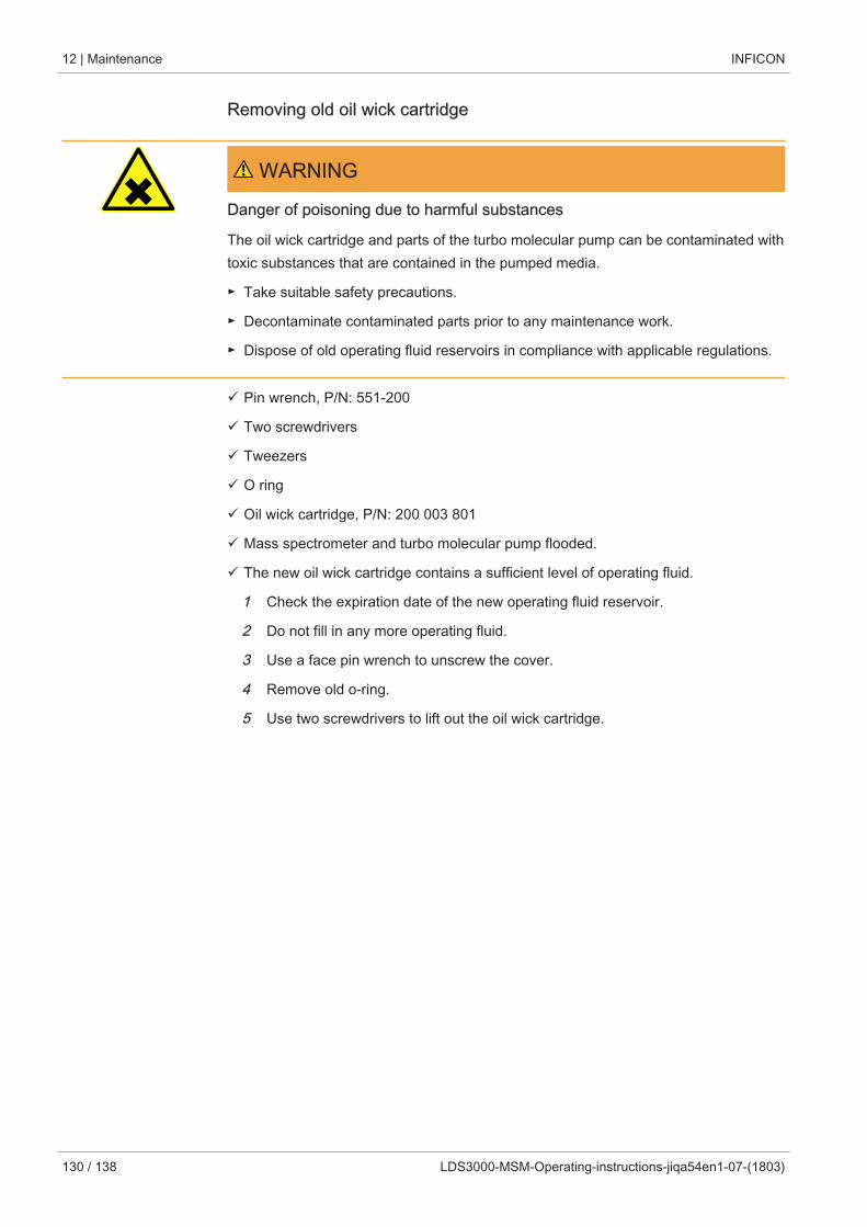
12 | Maintenance INFICON
130 / 138 LDS3000-MSM-Operating-instructions-jiqa54en1-07-(1803)
Removing old oil wick cartridge
WARNING
Danger of poisoning due to harmful substances
The oil wick cartridge and parts of the turbo molecular pump can be contaminated withtoxic substances that are contained in the pumped media.
► Take suitable safety precautions.
► Decontaminate contaminated parts prior to any maintenance work.
► Dispose of old operating fluid reservoirs in compliance with applicable regulations.
ü Pin wrench, P/N: 551-200
ü Two screwdrivers
ü Tweezers
ü O ring
ü Oil wick cartridge, P/N: 200 003 801
ü Mass spectrometer and turbo molecular pump flooded.
ü The new oil wick cartridge contains a sufficient level of operating fluid.
1 Check the expiration date of the new operating fluid reservoir.
2 Do not fill in any more operating fluid.
3 Use a face pin wrench to unscrew the cover.
4 Remove old o-ring.
5 Use two screwdrivers to lift out the oil wick cartridge.
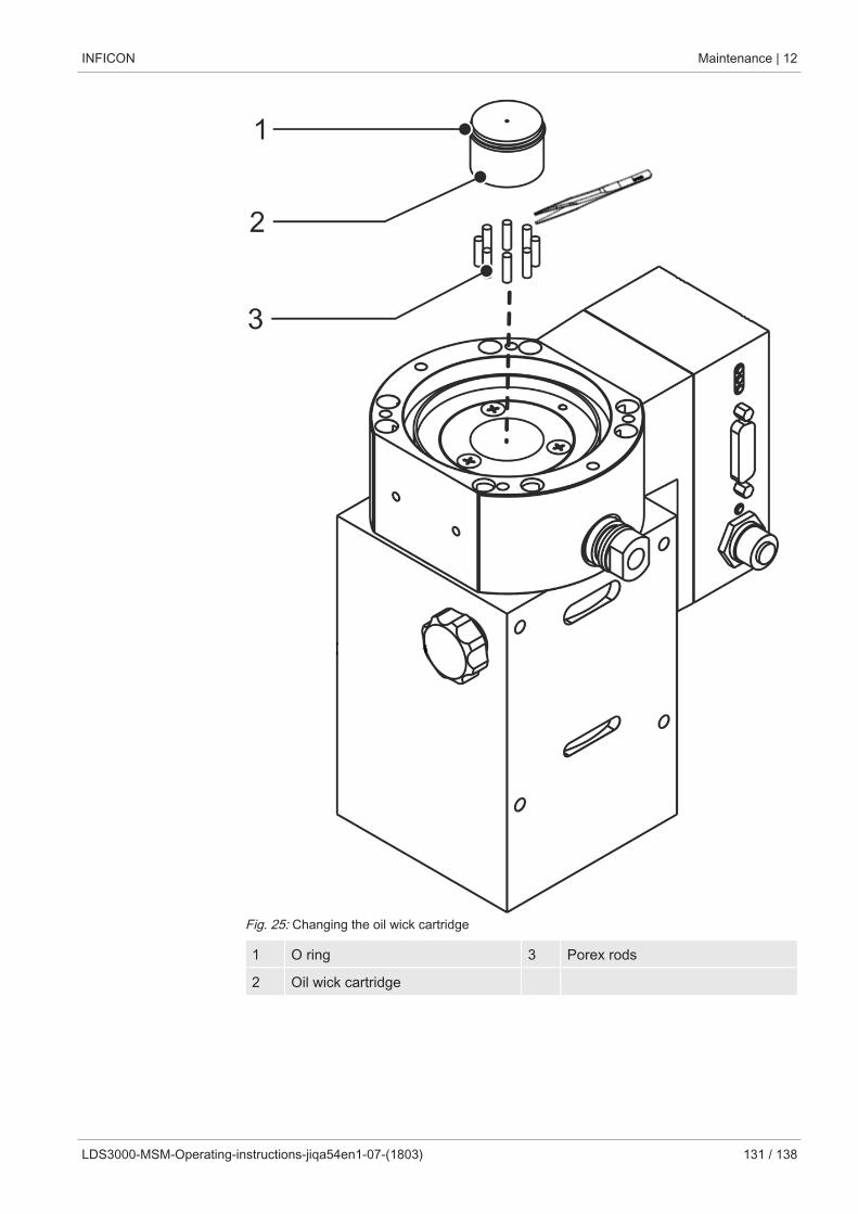
INFICON Maintenance | 12
LDS3000-MSM-Operating-instructions-jiqa54en1-07-(1803) 131 / 138
Fig. 25: Changing the oil wick cartridge
1 O ring 3 Porex rods
2 Oil wick cartridge
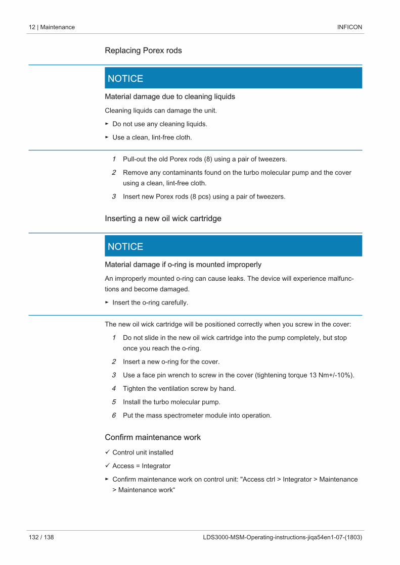
12 | Maintenance INFICON
132 / 138 LDS3000-MSM-Operating-instructions-jiqa54en1-07-(1803)
Replacing Porex rods
NOTICE
Material damage due to cleaning liquids
Cleaning liquids can damage the unit.
► Do not use any cleaning liquids.
► Use a clean, lint-free cloth.
1 Pull-out the old Porex rods (8) using a pair of tweezers.
2 Remove any contaminants found on the turbo molecular pump and the coverusing a clean, lint-free cloth.
3 Insert new Porex rods (8 pcs) using a pair of tweezers.
Inserting a new oil wick cartridge
NOTICE
Material damage if o-ring is mounted improperly
An improperly mounted o-ring can cause leaks. The device will experience malfunc-tions and become damaged.
► Insert the o-ring carefully.
The new oil wick cartridge will be positioned correctly when you screw in the cover:
1 Do not slide in the new oil wick cartridge into the pump completely, but stoponce you reach the o-ring.
2 Insert a new o-ring for the cover.
3 Use a face pin wrench to screw in the cover (tightening torque 13 Nm+/-10%).
4 Tighten the ventilation screw by hand.
5 Install the turbo molecular pump.
6 Put the mass spectrometer module into operation.
Confirm maintenance work
ü Control unit installed
ü Access = Integrator
► Confirm maintenance work on control unit: "Access ctrl > Integrator > Maintenance> Maintenance work“

INFICON Decommissioning the measuring instrument | 13
LDS3000-MSM-Operating-instructions-jiqa54en1-07-(1803) 133 / 138
13 Decommissioning the measuringinstrument
13.1 Shutting down the leak detector1 Switch off the leak detector on the power supply pack.
2 Wait until the turbo molecular pump has stopped running.
13.2 Disposing of the mass spectrometer moduleThe operator can dispose of the device or it can be sent to INFICON.
The device consists of materials that can be recycled. This option should be exercisedto prevent waste and also to protect the environment.
► For disposal, always comply with local and regional environmental and safety regu-lations.
13.3 Returning the mass spectrometer module
WARNING
Danger to health
Contaminated devices could endanger the health of INFICON employees.
► Fill in the declaration of contamination completely.
► Attach the declaration of contamination to the outside of the packaging.
The declaration of contamination is a legal requirement and serves to protect our em-ployees. INFICON sends devices which are sent without a completed declaration ofcontamination back to the sender.
See "Declaration of Contamination [} 136]".
14 | Appendix INFICON
134 / 138 LDS3000-MSM-Operating-instructions-jiqa54en1-07-(1803)
14 Appendix
14.1 CE Declaration of Conformity
INFICON Appendix | 14
LDS3000-MSM-Operating-instructions-jiqa54en1-07-(1803) 135 / 138
14.2 Declaration of Incorporation
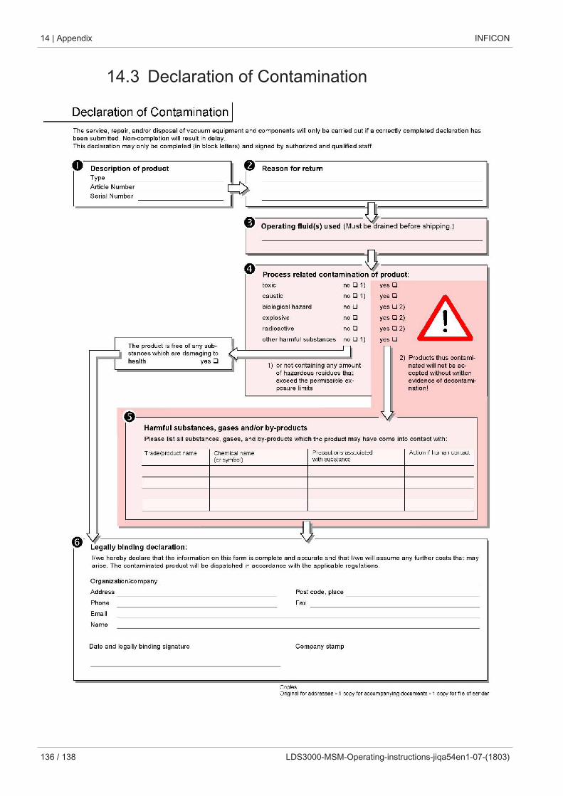
14 | Appendix INFICON
136 / 138 LDS3000-MSM-Operating-instructions-jiqa54en1-07-(1803)
14.3 Declaration of Contamination