Embed Size (px)
Citation preview

Load DesignUsers Manual
Load Design version 0.8
This software is still Under Development. It is NOT tested enough. NO WARRANTY.And this document is not checked well. It might contains mistakes.
1

Yuichi Yamauchi
Copyright © Yuichi Yamauchi. All rights reserved.
You may not redistribute this document or any part thereof. Use “Load Design” software under the terms of the License that is included in the software.
Yuichi Yamauchi
www.load-design.com
2

Words
Words used in “Load Design” software.
• Project File : File that contains the title, comment, model file name and result file name of Load Disign project. The file extension is “.ldproj”.
• Model Data : Data for finite element analysis with Load Design. It contains nodes, elements, analysis cases, restraint condition, force condition, etc. It is written in a model file. Result File also contains model data.
• Model File : File that model data is written in. It is a plain text file, so you can also make, edit it with other software. You can load it automatically when you open a project file by setting in the project file. ( Generally model file should be loaded automatically. ) The file extension is “.ldmodel”. You can open a model file directly without a project file. Load Design writes a model file in Unicode - UTF-8, and reads it as Unicode - UTF-8 or UTF-16.
• Result File : File that result data is written in when you run finite element analysis calculation. You can load it to a project file or a model file. You can load it automatically when you open a project fille by setting in the project file. You can not load it to a project file or a model file when the model data is edited after calculation. ( Result File can not be loaded to a project file or a model file that the model data is different from model data in the result data. ) Result File contains model data, so you can open a result file directly without project files or model files. The file extension is “.ldresult”.( Notes : Generally, Result File can not be loaded with different version of Load Design. When new version is released, you might not load the result file and you might need to re-calculate with model data. )
• Card : Card is each line of model data ( model files ). There are Node Cards, Element Cards, Case Cards, Restraint Cards, Force Cards, etc. Empty line of model data might be called as Card ( Null Card ). Mode data is constructed with Cards.
• Card Filter : Used to restrict cards to display in Card View or Graphic View in main window. It is also used to restrict cards to calculate or display values when you calculate or display result values, etc.
• Card Value, Card Value Expression : Values of cards, such as element card property or result values, or expression of the values.
3

Using Load Design First
1. Creating New Project• Open “Load Design” application on Finder.
• Select “File” - “New Project...” on main menu. Window “New Project” will appear.
• Input project name ( it will be the file name of the project file ) in “Project Name” text field, and push “Choose...” button on the right of “Directory” text field then select a directory to create project in. Check whether “Create the project directory” check button is ON, then push “Apply” button. A directory with name “Project Name” will be created in the directory that you specified with “Directory” text field, and a project file with name “Project Name.ldproj” will be created in it. Then, main window ( View Type : Project Info ) will appear.
4
• Input project title, version information of model, comment string in “Project Title”, “Version”, “Comment” text fields. ( All are optional. ) ( To input “New-Line” character in “Comment” text field, press “return” key while pressing “option” key. ) Input model file name in “Mode File Name” text field, then push “Create Model File” button. Model file with name “Model File Name.ldmodel” will be created. Also, input result file name in “Result File Name” text field. ( or you can make it empty. When it is empty, you will be asked the file name when you start calculation. )
• ( After making the model file, ) Select “Card View” with “View” pop-up menu on toolbar. Or you can select it with “View” on main menu. The view will change to “Card View”. ( You can select “Graphic View”. ( When model is empty, nothing will be displayed in “Graphic View”. ) ) At this time, the modification that you applied on “Project Info” view is not saved in the file. You can save the project file and the model file with “Save” button on toolbar or “File” - “Save” on main menu. ( When you are opening a project document, both the project file and the model file will be saved. )
5

2. Making Analysis Model
• Analysis Model is written in a model file. Mode file is a plain text file.
• You can make model with “Model Edit Window” ( You can open it with toolbar or main manu. ) or input/edit directly on “Card View”. Or you can make or edit it with other software, such as text editor, spread sheet software, script languages, etc. and you can do “Copy” and “Paste”.
• See “About Model Data” for details about model data.
• At this point, copy model data from “Load Design/sample/sample_model_01.txt”. Open “sample_model_01.txt” with a text editor software and do “Copy” the whole text, then do “Paste” on “Card View” of Load Design without selecting any rows. When some rows selected, press “esc” key or click the last row of “<end>” ( which is displayed in gray color ) or below to deselect rows. If you do “Paste” while a row selected, the text in clipboard will be inserted just above the selected row. You can delete some rows by selecting them and selecting “Edit” - “Delete” on main menu. Also, you can edit any row by double-clicking or pressing “return” key while selecting the row. ( Characters after back-slash character “\” is comment string ( which is displayed in green color ) and doesn’t affect to calculation, so you can edit, add them as you like. )
6
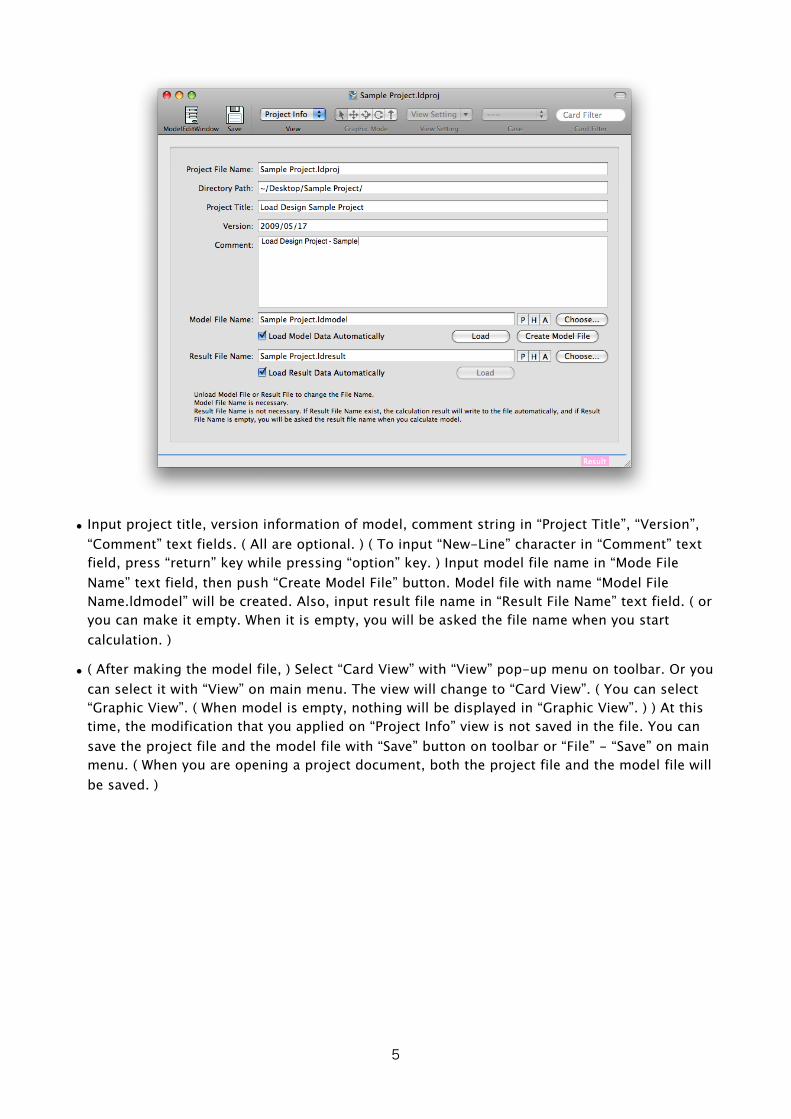
• Save files at this point. You can save the project file and the model file with “Save” button on toolbar or “File” - “Save” on main menu.
• You can see the model in graphic by selecting “Graphic View” with “View” pop-up menu on toolbar or “View” - “Graphic View” on main menu. You also can see the restraints or forces on any case by selecting cases with “Case” pop-up menu on toolbar or “View” - “Case” on main menu. ( In graphic view, restraints will be displayed in brown color and forces will be displayed in pink color ( in default condition ). )
7

• You can open several window for a same document ( project or model ) by selecting “Window” - “New Window” on main menu. You can set view type, etc. for each window, then you can make, edit, check model with seeing it with several windows.
• “Card Filter” text box exists on the right on toolbar ( in default condition ). If you input “type:Node” or “type:Element” in it, “only nodes” or “only elements” will be displayed in the window. Refer the term of “Card Filter” for details about Card Filter.
8
Restraints and Forces are displayed differently ( after ver0.8.1 ).

3. Calculation
• Select “Calculation” - “Run Calculation” on main menu. When you are opening a project document, dialog sheet for “Version” string will be displayed. ( When you are opening a model file ( file extension: .ldmodel ), the dialog sheet will not be displayed. ) You can change “Version” string of the project. ( This is same as “Version” string in “Project Info” View. You will be asked every time when you start calculation and you can change it. ) Push “Save and Calculate” or “Calculate Without Save” button.
• When the result file name is written in the project file, calculation will start. When the result file name is not written or you are opening a model file ( not a project file ), a dialog sheet will be displayed and you can set the result file name. ( You don’t need to save a result file after calculation. ( Notes : You can’t save result files later with current version of Load Design. ) ) You also can set wether the result data is automatically loaded to the project or the model when the calculation is done. ( You need to load the result file manually when you don’t specify it. ) Push “OK” button, then calculation will start.
9

• As calculation starts, “Calculation” window will be displayed and progress of the calculation will be displayed. You can do “Pause” or “Quit” while calculation.
• In case you specified to load the result file in the project file or when calculation start, the result data will be loaded automatically. In case you don’t specified it, load result data with selecting “File” - “Load Result Data” on main menu. When the result data is loaded, letters of “Result” is displayed in ( deep ) pink color on the bottom right of the main window. When the result data is not loaded, the letters is displayed in light pink color.
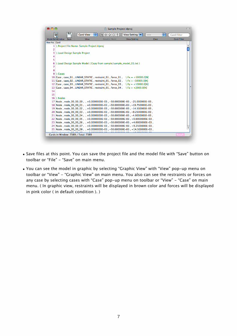
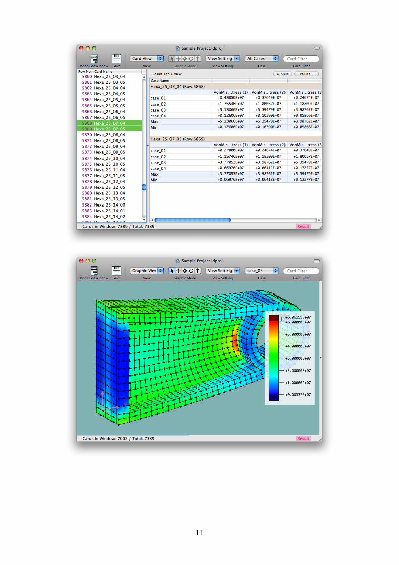
• You can see result data by selecting proper View Setting with “View Setting” menu on toolbar or “View” - “View Setting” on main menu. You might need to specify cases of displaying result by selecting cases with “Case” menu on toolbar or “View” - “Case” on main menu. On “Card View”, as you select “Result” in “View Setting” menu and open “Result Table View” which is closed in the right edge of the main window ( you can open Result Table View by dragging mouse when mouse pointer changed around the right edge of the window ), you can see node displacement by selecting node cards on left view, or Von Mises Stress of elements by selecting element cards. On “Graphic View”, as you select “Displacement” , “VonMisesStress” or “Displacement & VonMisesStress” in “View Setting” menu, you can see it in graphic view. Or you can specify view setting by selecting “View Setting...” in “View Setting” menu.
10
11

4. Other
• While the result file is loaded to a project document or a model document, you can’t edit model data ( model file ). To edit model data, you need to unload the result file by selecting “File” - “Unload Result Data” on main menu. Then you can edit model data. But, result files contains the model data when it is calculated, in case you edit model data after the result data calculated, the result data ( that is calculated with other model data ( old model data ) ) can’t be loaded. ( You can open the result file directly. )
• To quit application, select “Load Design” - “Quit Load Design” on main menu.
12

About Model Data
1. Finite Element Analysis in Load Design• With finite element analysis, you divide the object ( or structure ) which you analyze into
elements with simple shape and simply deform ( Element ) and simulate the object as a set of elements, then calculate stress inside or deformation when forces are applied to the object. ( Ref : Figure below ) All elements are connected each other by nodes ( Node ) ( or Degree of Freedom (DOF) of nodes ( Tx, Ty, Tz ( translational DOF ), Rx, Ry, Rz ( rotational DOF ) ) ). Also restraints and forces are applied to nodes. Load Design calculate by displacement-method. It builds stiffness matrix of while model from element’s stiffness matrix, applies restraint condition and force condition to it, then calculates and solve stiffness equation ( equation for displacement ) and get displacement of all nodes. Other values like loads, stresses in element are calculated by node displacement. Load Design can calculate with “Linear-Static” analysis only. See more about finite element analysis ( or finite element method, FEA, FEM ) in other books, etc.
• Load Design can analyze several analysis cases ( Case ) in a model. You can specify different restraint condition, force condition to each cases. Elements are common for all cases. ( You can’t change, add/delete elements by cases. ) Displacement of nodes, loads, stresses in elements are calculated for each cases.
• Load Design doesn’t specify units. ( [m], [N], [kgf], etc. ) All values in a model data, such as node location, element’s section area, material’s young’s modulus, forces must be conformed to one system of units. Result value, such as node displacement, element’s loads, stresses will be under the system of units that you used in the model data. For example, in case of using [m] ( meter ) for length, [N] ( newton ) for forces, unit of stress will be [N/m2] = [Pa] ( pascal ). In case of using [mm] for length, [kgf] for forces, unit of stress will be [kgf/mm2].
• To analyze, you make the model data to simulate object and force condition ( Modeling ), modeling must be done appropriately, such as dividing into elements ( kind of elements, number of elements, shape of elements, etc. ), restraint condition, force condition, examination about wether Linear-Static is suitable or not, and so on. You need to understand the performance of elements. Load Design might not appropriate for your analysis.
F
Finite Element Analysis ModelObject for Analysis
F
Fig. - Finite Element Analysis Model
13

2. Summary of Mode Data
• Model Data is a data of calculation model with finite element analysis. It includes all about calculation with finite element analysis. There are the form of object for analysis ( nodes, elements divided into ), material properties, calculation cases, restraint conditions and force conditions. Restraint conditions and force conditions are specified by cases each
• Model data is stored in a model file ( the file extension is “.ldmodel” ).
• Mode File is a plain text file. ( The encoding is Unicode - UTF-8 or UTF-16 for reading, UTF-8 for writing. ) It can be made or edited by other software which can make or edit text files.
• Model data is made with “Card”. Card is each row ( each line ) of model data. Empty row ( which might have comment string ) might be called as Card ( Null Card ). A card ( except Null Card ) has several columns and separated with camma character ‘,’.
• You can write comment string on any row ( any card ) after ‘\’ ( back slash character ). Comment string doesn’t affect to calculation result.
• There are several kind of Cards ( Card Type ), such as Node Card ( Node Card Type ), Element Card ( Element Card Type ), Element Property Card, Case Card, Restraint Card, Force Card ( and Null Card ). The first column of card ( except Null Card ) is the name of Card Class ( kind of card : “Node”, “Rod”, “Quad”, “Case”, “Force”, etc. ). ( Note: Both “Rod” and “Quad” are Element Card. )
• The second column of card is “Card Name”. All cards ( except Null Card ) have a card name, and referred from other cards with it. ( For example, element cards refer some node cards. ) You can use characters ‘a-z’, ‘A-Z’, ‘0-9’, ‘_’ ( under-bar ), non-ASCII characters, etc. for Card Name. You can not use other ASCII characters ( !”#$%&’()*+,-./:;<=>?@[\]^`{|}~ and ‘ ‘(space character) ).
• You can not use same card name for several cards of Node Cards, Element Cards, Element Property Cards, Case Cards. ( Only one card for one name of Node Cards, Element Cards, Element Property Cards, Case Cards can be exist. ) Several cards of Restraint Cards, Force Cards with one name can be exist. ( When you specify a card name for restraint cards or force cards, all cards with the name of Restraint Cards, Force Cards will be applied. )
• Node Card defines node information. Elements are connected to other elements with nodes. Restraints and forces are applied to nodes.
• There are several element card classes such as Rod ( Axial-Force Element ), Quad ( Quadrangle Shell Element ), Hexa ( Hexahedral Solid Element ), etc. Element Card referes several node cards and the shape is formed by nodes. Elements are connected to other elements by nodes. It usually refer Element Property Card.
• Element Property Card is referred from Element Card and defines element property. There are Card Classes such as RodProp ( Property of Rod Element ), ShellProp ( Property of Shell Element, such as Quad ), SolidProp ( Property of Solid Element, such as Hexa ). Material Card might be also called as Element Property Card.
• Case Card defines analysis cases. Analysis type ( Linear-Static only ), Restraint Card ( restraint confition ) and Force Card ( force condition ) are specified by a case card. Several cards may exist with one card name of Restraint Cards or Force Cards. All cards ( Restraint Cards, Force Cards ) of the name are applied for the case.
14

• Restraint Card is referred from Case Card and specifies restraints of node’s DOF ( Degree of Freedom ) ( fixing DOF or equation between DOFs ). Restraint Cards which are referred from a Case Card are applied to the case. ( Several Restraint Cards might exist with same card name. ) With Linear-Static analysis, several DOFs need to be restrained in order not to move whole structure or part of structure without stiffness.
• Force Card is referred from Case Card and specifies forces. Force Cards which are referred from Case Card applied to the analysis case. ( Several Force Cards might exist with same card name. )
• Basically, you can write cards with any order. For example, element card referes node cards but which card ( node card or element card ) can be above or below. But calculation time might vary by order of node cards. ( Ref: term of “Miscellaneous - About Band Width of Stiffness Matrix, etc.” )
15
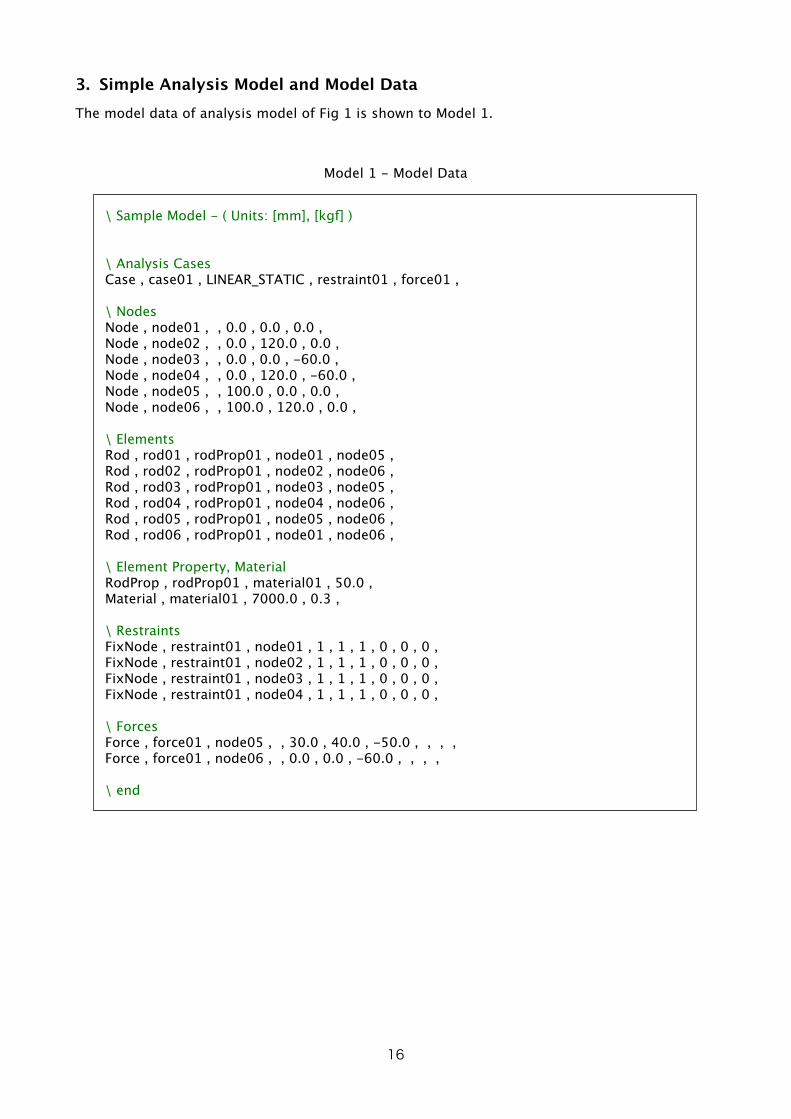
3. Simple Analysis Model and Model DataThe model data of analysis model of Fig 1 is shown to Model 1.
Model 1 - Model Data
\ Sample Model - ( Units: [mm], [kgf] )
\ Analysis CasesCase , case01 , LINEAR_STATIC , restraint01 , force01 ,
\ NodesNode , node01 , , 0.0 , 0.0 , 0.0 , Node , node02 , , 0.0 , 120.0 , 0.0 , Node , node03 , , 0.0 , 0.0 , -60.0 , Node , node04 , , 0.0 , 120.0 , -60.0 , Node , node05 , , 100.0 , 0.0 , 0.0 , Node , node06 , , 100.0 , 120.0 , 0.0 ,
\ ElementsRod , rod01 , rodProp01 , node01 , node05 , Rod , rod02 , rodProp01 , node02 , node06 , Rod , rod03 , rodProp01 , node03 , node05 , Rod , rod04 , rodProp01 , node04 , node06 , Rod , rod05 , rodProp01 , node05 , node06 , Rod , rod06 , rodProp01 , node01 , node06 ,
\ Element Property, MaterialRodProp , rodProp01 , material01 , 50.0 , Material , material01 , 7000.0 , 0.3 ,
\ RestraintsFixNode , restraint01 , node01 , 1 , 1 , 1 , 0 , 0 , 0 , FixNode , restraint01 , node02 , 1 , 1 , 1 , 0 , 0 , 0 , FixNode , restraint01 , node03 , 1 , 1 , 1 , 0 , 0 , 0 , FixNode , restraint01 , node04 , 1 , 1 , 1 , 0 , 0 , 0 ,
\ ForcesForce , force01 , node05 , , 30.0 , 40.0 , -50.0 , , , , Force , force01 , node06 , , 0.0 , 0.0 , -60.0 , , , ,
\ end
16

X
Y
Z
F = ( +30, +40, -50 )
F = ( 0, 0, -60 )
120
100
60
node01 (Fixed)
node02 (Fixed)
node03 (Fixed)
node04 (Fixed)
node05
node06
Fig 1 - Analysis Model
• String after ‘\’ ( Back slash character ) to the end of the row is comment string. Comment string can be written after valid cards.
\ Sample Model - ( Units: [mm], [kgf] )
Node , node01 , , 0.0 , 0.0 , 0.0 , \ Comment can be written after cards
• “Node” card below defines a node ( location: ( x, y, z ) = ( 0.0, 0.0, 0.0 ) ) with name “node01”.
Node , node01 , , 0.0 , 0.0 , 0.0 ,
• “Rod” card below defines a rod element with name “rod01”. Two nodes on the tip are “node01” and “node05”. It refers a card with name “rodProp01” for rod element property ( section area, Young’s modulus of material, etc. )
Rod , rod01 , rodProp01 , node01 , node05 ,
• “RodProp” card below defines rod property ( section area: 50.0 [mm2] ) with name “ropProp01”. It refers a card of name “material01” for materia property.
• “Material” card below defines material property ( Young’s modulus : 7000.0[kg/mm2], Poissons ratio: 0.3 ) with name “material01”.
RodProp , rodProp01 , material01 , 50.0 , Material , material01 , 7000.0 , 0.3 ,
• “Case” card below defines an analysis case ( analysis type: “LINEAR_STATIC” ) with name “case01”. It refers cards with name “restraint01” for restraint condition and cards with name “force01” for force condition.
Case , case01 , LINEAR_STATIC , restraint01 , force01 ,
17

• “FixNode” card below defines restraint which restrains DOF Tx, Ty, Tz of node “node01”. ( It doesn’t restrain Rx, Ry, Rz. ) ( Tx, Ty, Tz: Translational DOF, Rx, Ry, Rz: Rotational DOF )
• Several restraint cards exist with name “restraint01” in Model 1. Case “case01” specifies “restraint01”, so all restraint with name “restraint01” is applied to the case.
• With Linear-Static analysis, several DOFs need to be restrained in order not to move whole structure or part of structure without stiffness.
FixNode , restraint01 , node01 , 1 , 1 , 1 , 0 , 0 , 0 ,
• “Force” Card below defines force which forces ( Fx, Fy, Fz, Mx, My, Mz ) = ( +30, +40, -50, 0, 0, 0 ) [kgf] on node “node05”.
• Several force cards exist with name “force01” in Model 1. Case “case01” specifies “force01”, so all force with name “force01” is applied to the case.
Force , force01 , node05 , , 30.0 , 40.0 , -50.0 , , , ,
4. About Each Card Classes• For description about each Card Classes, refer the term “About Card Classes”.
18

How to Use Load Design
1. Interface of Load Design
Main Window - Common
• Toolbar
• “Model Edit Window” button : It opens “Model Edit Window”.
• “Save” Button : It saves Project File and Model File.
• “View Type” Pop-up Menu : It changes View Type.
• “Graphic Mode” Switch Button : On Graphic View, it changes mouse mode. ( “Arrow” : Selecting cards ( nodes, elements, etc ) / “Translate” / “Rotate 1” / “Rotate 2” / “Scale” )
• “View Setting” Menu : On Card View or Graphic View, it applies prearranged set of view setting or shows “View Setting” sheet.
• “Case” Pop-up Menu : It specifies analysis cases for the window. Only cards which related to the specified case are shown in Card View or Graphic View. To not specify cases, select “---”. To specify all cases, select “All Cases”. To specify one case, select the case which is outside of “Some Cases” sub-menu. To specify several cases, select the cases in “Some Cases” sub-menu. When specified cases, only cards which related to the case specified are shown in Card View or Graphic View. ( Restraint Cards or Force Cards which is not used with the case are not shown. )
19
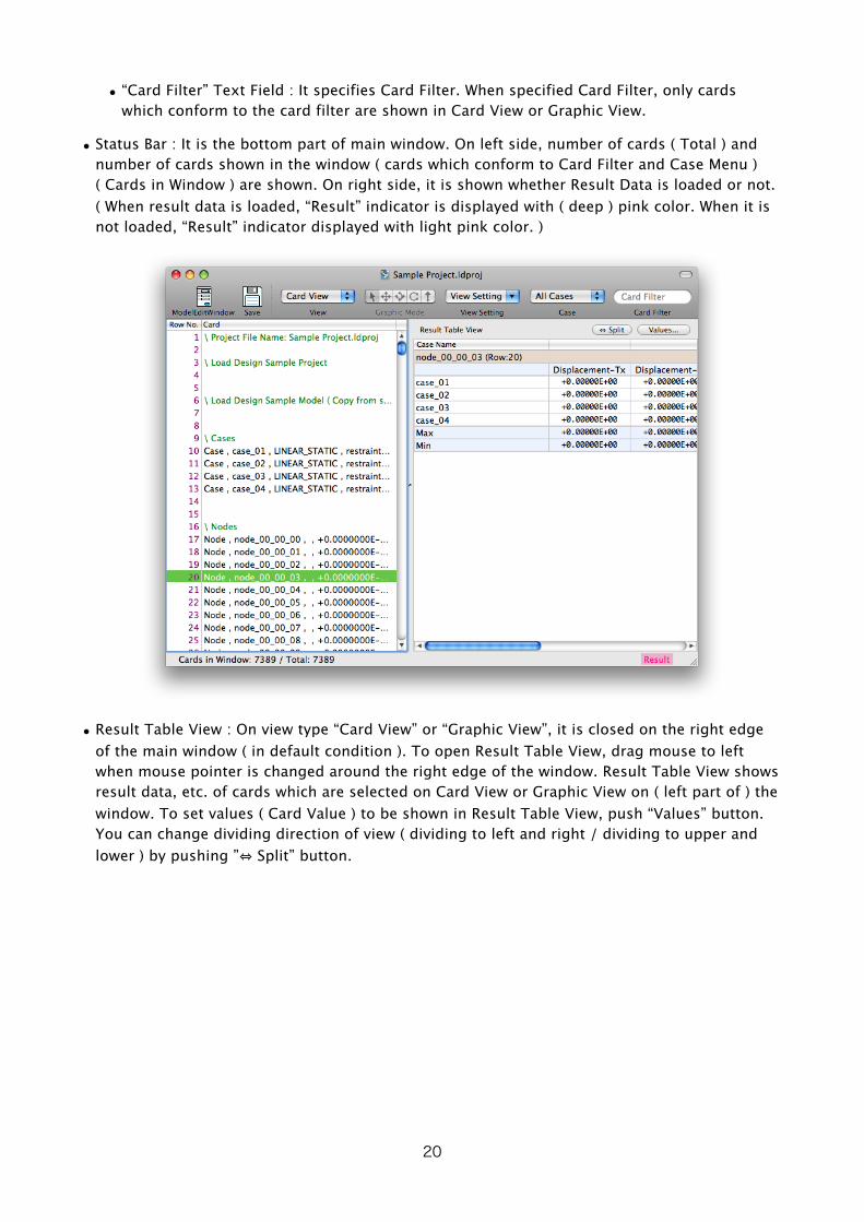
• “Card Filter” Text Field : It specifies Card Filter. When specified Card Filter, only cards which conform to the card filter are shown in Card View or Graphic View.
• Status Bar : It is the bottom part of main window. On left side, number of cards ( Total ) and number of cards shown in the window ( cards which conform to Card Filter and Case Menu ) ( Cards in Window ) are shown. On right side, it is shown whether Result Data is loaded or not. ( When result data is loaded, “Result” indicator is displayed with ( deep ) pink color. When it is not loaded, “Result” indicator displayed with light pink color. )
• Result Table View : On view type “Card View” or “Graphic View”, it is closed on the right edge of the main window ( in default condition ). To open Result Table View, drag mouse to left when mouse pointer is changed around the right edge of the window. Result Table View shows result data, etc. of cards which are selected on Card View or Graphic View on ( left part of ) the window. To set values ( Card Value ) to be shown in Result Table View, push “Values” button. You can change dividing direction of view ( dividing to left and right / dividing to upper and lower ) by pushing ”⇔ Split” button.
20
Main Menu
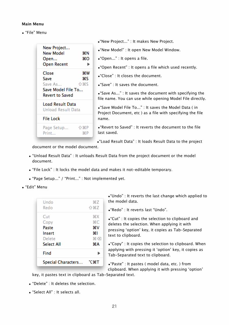
• “File” Menu
•“New Project...” : It makes New Project.
•“New Model” : It open New Model Window.
•“Open...” : It opens a file.
•“Open Recent” : It opens a file which used recently.
•“Close” : It closes the document.
•“Save” : It saves the document.
•“Save As...” : It saves the document with specifying the file name. You can use while opening Model File directly.
•“Save Model File To...” : It saves the Model Data ( in Project Document, etc ) as a file with specifying the file name.
•“Revert to Saved” : It reverts the document to the file last saved.
•“Load Result Data” : It loads Result Data to the project document or the model document.
• “Unload Result Data” : It unloads Result Data from the project document or the model document.
• “File Lock” : It locks the model data and makes it not-editable temporary.
• “Page Setup...” / “Print...” : Not implemented yet.
• “Edit” Menu
•“Undo” : It reverts the last change which applied to the model data.
•“Redo” : It reverts last “Undo”.
•“Cut” : It copies the selection to clipboard and deletes the selection. When applying it with pressing ‘option’ key, it copies as Tab-Separated text to clipboard.
•“Copy” : It copies the selection to clipboard. When applying with pressing it ‘option’ key, it copies as Tab-Separated text to clipboard.
•“Paste” : It pastes ( model data, etc. ) from clipboard. When applying it with pressing ‘option’
key, it pastes text in clipboard as Tab-Separated text.
• “Delete” : It deletes the selection.
• “Select All” : It selects all.
21

• “Find” Menu
• “Find...” : It opens Find Panel.
• “Find Next” / “Find Previous” : It search Find String in Find Panel to right direction / opposite direction.
• “Use Selection for Find” : It sets the selection to Find String.
• “Scroll to Selection” : It scrolls to be shown the selection. ( Only on Card View )
• “View” Menu
•“Card View” / “Graphic View” / “Project Info” ( / “Result Info” ) : It changes View Type. It is same as “View Type” menu on toolbar.
•“Move Mode” : On Graphic View, it specifies mouse mode. It is same as “Graphic Mode” switch button on toolbar. ( “Arrow” : Selecting cards ( nodes, elements, etc ) / “Translate” / “Rotate 1” / “Rotate 2” / “Scale” )
•“View Setting” : On Card View or Graphic View, it applies prearranged set of view setting or showing “View Setting” sheet. It is same as “View Setting” menu on toolbar.
•“Case” Menu : It specifies analysis cases for the window. Only cards which related to the specified case are shown in
Card View or Graphic View. It is same as “Case” menu on toolbar. To not specify cases, select “---”. To specify all cases, select “All Cases”. To specify one case, select the case which is outside of “Some Cases” sub-menu. To specify several cases, select the cases in “Some Cases” sub-menu. When specified cases, only cards which related to the case specified are shown in Card View or Graphic View. ( Restraint Cards or Force Cards which is not used with the case are not shown. )
• “Fit in View” : On Graphic View, it adjust the object location and size to fit in Graphic View.
• “Set Direction” Menu : On Graphic View, it changes direction of the object. It also adjust the object location and size to fit in Graphic View.
• “Model” Menu
•“Open Model Edit Window” : It opens “Model Edit Window”. You can do adding cards, etc.
•“Retry All Error Cards” : It tries all Error Card to be registered without changes cards. When the error reason of Error Cards were by competition about card names and the other cards which courses the
competition was modified, the error might be removed.
• “Find Error Card” Menu
• “Next Error Card” / “Previous Error Card” : It searches Error Card to right direction / opposite direction. When there is no error cards, it searched a card which returns YES for “hasError” ( Ref: Term of “Card Filter” ).
22
• “Next Incomplete Card” / “Previous Incomplete Card” : It searches a card which returns YES for “hasError” ( Ref: Term of “Card Filter” ) ( it includes Error Cards ).
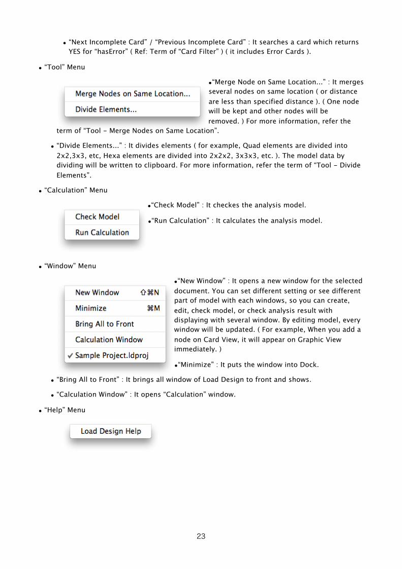
• “Tool” Menu
•“Merge Node on Same Location...” : It merges several nodes on same location ( or distance are less than specified distance ). ( One node will be kept and other nodes will be removed. ) For more information, refer the
term of “Tool - Merge Nodes on Same Location”.
• “Divide Elements...” : It divides elements ( for example, Quad elements are divided into 2x2,3x3, etc, Hexa elements are divided into 2x2x2, 3x3x3, etc. ). The model data by dividing will be written to clipboard. For more information, refer the term of “Tool - Divide Elements”.
• “Calculation” Menu
•“Check Model” : It checkes the analysis model.
•“Run Calculation” : It calculates the analysis model.
• “Window” Menu
•“New Window” : It opens a new window for the selected document. You can set different setting or see different part of model with each windows, so you can create, edit, check model, or check analysis result with displaying with several window. By editing model, every window will be updated. ( For example, When you add a node on Card View, it will appear on Graphic View immediately. )
•“Minimize” : It puts the window into Dock.
• “Bring All to Front” : It brings all window of Load Design to front and shows.
• “Calculation Window” : It opens “Calculation” window.
• “Help” Menu
23

Main Window - Card View
• It displays model data as text format ( in default condition ).
• You can set items to be shown ( row number, contents of card, card name, error description ) with “View Setting” menu. You can also set values to be shown in Result Table View ( Card Value ) with it.
• When Card Filter or Cases are specified with “Card Filter” or “Case” menu, only cards which conform to them are shown in Card View.
24

• ( In default condition, ) Result Table View is closed on the right edge of window. As you opens Result Table View, values ( result values, etc. ) of cards which you select on Card View are shown on Result Table View.
25

Main Window - Graphic View
• It displays model ( nodes, elements, forces, restraints ) in graphic. It can also display scaler value ( Von Mises Stress, etc. ) with color or/and displacement with deformation.
• You specifies mouse mode ( “Arrow” : Selecting cards ( nodes, elements, etc ) / “Translate” / “Rotate 1” / “Rotate 2” / “Scale” ) with “Graphic Mode” switch button on toolbar or “View” -
26
Restraints and Forces are displayed differently ( after ver0.8.1 ).
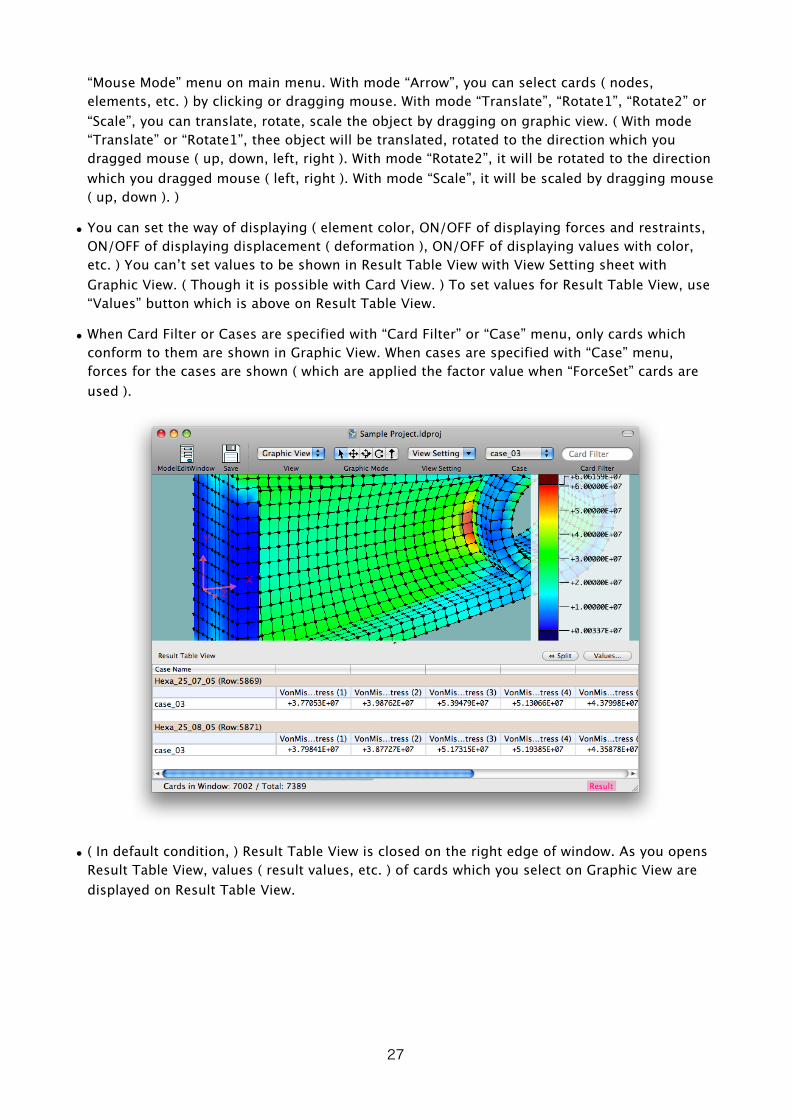
“Mouse Mode” menu on main menu. With mode “Arrow”, you can select cards ( nodes, elements, etc. ) by clicking or dragging mouse. With mode “Translate”, “Rotate1”, “Rotate2” or “Scale”, you can translate, rotate, scale the object by dragging on graphic view. ( With mode “Translate” or “Rotate1”, thee object will be translated, rotated to the direction which you dragged mouse ( up, down, left, right ). With mode “Rotate2”, it will be rotated to the direction which you dragged mouse ( left, right ). With mode “Scale”, it will be scaled by dragging mouse ( up, down ). )
• You can set the way of displaying ( element color, ON/OFF of displaying forces and restraints, ON/OFF of displaying displacement ( deformation ), ON/OFF of displaying values with color, etc. ) You can’t set values to be shown in Result Table View with View Setting sheet with Graphic View. ( Though it is possible with Card View. ) To set values for Result Table View, use “Values” button which is above on Result Table View.
• When Card Filter or Cases are specified with “Card Filter” or “Case” menu, only cards which conform to them are shown in Graphic View. When cases are specified with “Case” menu, forces for the cases are shown ( which are applied the factor value when “ForceSet” cards are used ).
• ( In default condition, ) Result Table View is closed on the right edge of window. As you opens Result Table View, values ( result values, etc. ) of cards which you select on Graphic View are displayed on Result Table View.
27

Main Window - Project Info View ( Only when Project File is opened. )
• It shows information of Project File.
• You sets project title, version string, comment string, and file names ( file path ) of model file and result file, whether loading result file automatically ( if it exists ). To input “New-Line” character in “Comment” text field, press “return” key while pressing “option” key.
• When you create a new project, input model file name ( file path ) and push “Create Model File” button then the model file will be create. When model file has already exist, input model file name ( file path ) and push “Load” button then the model file will be loaded. Usually, “Load Model Data Automatically” check button should be ON. ( When it is ON, the model file will be loaded with the project file is opened. )
• When Result File Name is written, the result file name will be created when you calculate analysis model. When result file name is not written, you will be asked the file name when you start calculation. When “Load Result Data Automatically” check button is ON, result file will be loaded as project file opened if the result file exist. ( In case that result file is not loaded while the file exists, push “Load” button. Reason of failed will be shown. )
• Buttons “P”, “H”, “A” or “Choose...” on Project Info View doesn’t work.
28

Main Window - Result Info View ( Only when Result File is opened. )
• It shows information of result file.
Model Edit Window
• You can do adding cards, etc. with it.
29
2. Creating New Project or New Model
Creating New Project
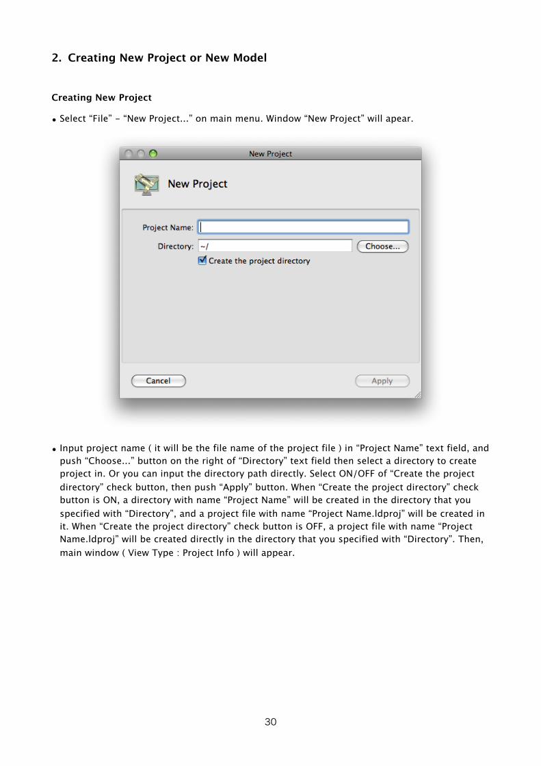
• Select “File” - “New Project...” on main menu. Window “New Project” will apear.
• Input project name ( it will be the file name of the project file ) in “Project Name” text field, and push “Choose...” button on the right of “Directory” text field then select a directory to create project in. Or you can input the directory path directly. Select ON/OFF of “Create the project directory” check button, then push “Apply” button. When “Create the project directory” check button is ON, a directory with name “Project Name” will be created in the directory that you specified with “Directory”, and a project file with name “Project Name.ldproj” will be created in it. When “Create the project directory” check button is OFF, a project file with name “Project Name.ldproj” will be created directly in the directory that you specified with “Directory”. Then, main window ( View Type : Project Info ) will appear.
30

• Input project title, version information of model, comment string in “Project Title”, “Version”, “Comment” text fields. ( All are optional. ) ( To input “New-Line” character in “Comment” text field, press “return” key while pressing “option” key. ) Input model file name in “Mode File Name” text field, then push “Create Model File” button. Model file with name “Model File Name.ldmodel” will be created. ( You can load existing model file by input the file name in “Model File Name” text field and pushing “Load” button. ) Also, input result file name in “Result File Name” text field. ( or you can make it empty. When it is empty, you will be asked the file name when you start calculation. )
• ( After making or loading model file ) Select “Card View” with “View” pop-up menu on toolbar. Or you can select it with “View” on main menu. View will change to “Card View”. ( You can select “Graphic View”. ( When model is empty, nothing will be displayed in “Graphic View”. ) ) At this time, the modification that you applied on “Project Info” view is not saved in the file. You can save the project file and the model file with “Save” button on toolbar or “File” - “Save” on main menu. ( When you are opening a project document, both the project file and the model file will be saved. )
Creating New Model
• To create new model, select “File” - New Mode” in main menu. New Model Document will appear.
3. Reading Existing Project, Existing Model, or Result File• To open an existing project file, model file, or result file, double-click the file on “Finder”. Or
select “File” - “Open...” on main menu and select the file on “Open” dialog.
31
4. Making Model ( Inputing or Editing Model )• To input ( add ) an empty row, select “Edit” - “Insert” on main menu. When a row ( card ) is
selected, the empty row will be inserted just above of the card selected. When no row selected, the empty row will be add at last of model data.
• To edit a row ( card ), double-click the row in Card View, or press “return” key while the card is selected. When you double-click a card ( node, element, etc. ) in Graphic View, a text field will appear under the toolbar and you can edit.
• You can input card with “Model Edit Window”. To add a card, select “Add” with “Action” popup menu on Model Edit Window. When a row ( card ) is selected, the empty row will be inserted just above of the card selected. When no row selected, add the empty row will be add at last of model data. You can open “Model Edit Window” with a button on toolbar or “Model” - “Open Model Edit Window” on main menu.
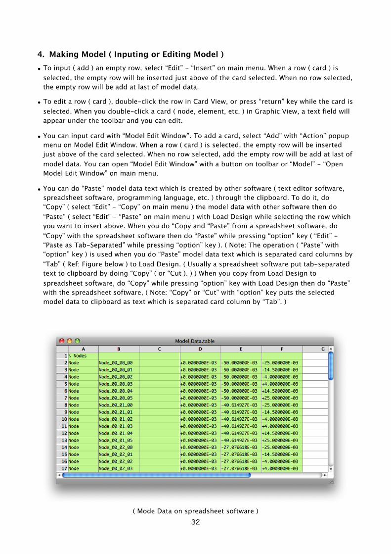
• You can do “Paste” model data text which is created by other software ( text editor software, spreadsheet software, programming language, etc. ) through the clipboard. To do it, do “Copy” ( select “Edit” - “Copy” on main menu ) the model data with other software then do “Paste” ( select “Edit” - “Paste” on main menu ) with Load Design while selecting the row which you want to insert above. When you do “Copy and “Paste” from a spreadsheet software, do “Copy” with the spreadsheet software then do “Paste” while pressing “option” key ( “Edit” - “Paste as Tab-Separated” while pressing “option” key ). ( Note: The operation ( “Paste” with “option” key ) is used when you do “Paste” model data text which is separated card columns by “Tab” ( Ref: Figure below ) to Load Design. ( Usually a spreadsheet software put tab-separated text to clipboard by doing “Copy” ( or “Cut ). ) ) When you copy from Load Design to spreadsheet software, do “Copy” while pressing “option” key with Load Design then do “Paste” with the spreadsheet software, ( Note: “Copy” or “Cut” with “option” key puts the selected model data to clipboard as text which is separated card column by “Tab”. )
( Mode Data on spreadsheet software )32

• By selecting “Model withError” in “View Setting” menu on toolbar or main menu with Card View, errors on cards are shown in “Error / Warning” column. ( Refer the term of “Displaying Result with Card View ( with Result Table View ) and View Setting” for more about “View Setting”. ) And, by selecting “Model” - “Find Error Card” - “Next Error Card/Previous Error Card”, etc. on main menu, the next ( or previous ) error card will be selected and shown. You need to fix all errors on model data before calculation.
5. About Card Filter, Case Menu• By input “type:Node”, “type:Element”, etc. on “Card Filter” text field, you can restrict cards
which are shown in Card View or Graphic View. Refer the term of “About Card Filter” for details about Card Filter expression.
• By specifying analysis cases with “Case Menu”, cards which are not used in the cases ( case cards, restraint cards, force cards ) will not be shown in Card View or Graphic View. In Graphic View, forces which are applied to the cases are shown. ( Forces with factors when “ForceSet” cards are used. ) Also, Result Table View shows values for specified cases.
6. Calculation• To check model data, select “Calculation” - “Check Model” on main menu.
• To run the calculation, select “Calculation” - “Run Calculation” on main menu. When the document is a Project Document, a dialog for “Version” string will be displayed. ( When it is a model document, it will not be displayed. ) You can change “Version” string here. ( It is same as “Version” in “Project Info” view. You will be asked every time you runs calculation and you can edit, input it. ) Push “Save and Calculate” button or “Calculate without Save” button.
• When the result file name is written in the project file, the calculation will start. When it is not written or the document is a model document, a dialog will be displayed and you input result file name. ( You don’t need save the result file. ( Note: You can’t save the result file later. ) ) You specify whether the result file is loaded when the calculation has done. ( When you specify Not to be loaded, you need load the result file by yourself after the calculation has done. ) By pushing “OK” button, the calculation will start.
33

• As calculation starts, “Calculation” window will be displayed and the progress of calculation will be shown. You can do “Pause” or “Quit” the calculation.
• When you specified the result file to be loaded in project file or when calculation starts, as the calculation has done, the result file will be automatically loaded. When you specified not to be loaded, you can do “File” - “Load Result Data” on main menu to load it. When the result data is loaded, “Result” indicator which is located on the status bar located on the bottom of the window shows in ( deep ) pink color. When result file is not loaded, it shows in light pink color.
7. Displaying Result with Card View ( with Result Table View ) and View Setting
• On Card View, you can change View Setting with “View Setting” menu on toolbar or main menu by selecting “Model”, “Model with Error” or “Result”. When you select “Result”, result data for cards which is selected in Card View ( node’s displacement, element’s Von Mises Stress ) are shown in “Result Table View”. ( Result Table View is located on the right edge of Card View. Refer the term of “1. Interface of Load Design” for the way to to open the Result Table View. )
• By selecting “View Setting...” in “View Setting” menu on toolbar or main menu, “View Setting sheet” for Card View will be displayed. ( “Model”, “Model with Error” and “Result” in “View Setting” menu are pre-arranged sets of this View Setting. ) You can specify columns to be displayed, content values for shown in Result Table View. To input New-Line character in “Values” text field, press “return” key while pressing “option” key.
• Content values for shown in Result Table View can be specified also with a sheet which is displayed by pushing “Values...” button which is located above Result Table View on the right.
34
• Refer the term of “Displaying with Result Table View” for the way to specify contents of Result Table View or more about Result Table View.
8. Displaying Result with Graphic View and View Setting• On Graphic View, you can change View Setting with “View Setting” menu on toolbar or main
menu by selecting “Model”, “Displacement”, “VonMisesStress” or “Displacement & VonMisesStress”. When you select “Displacement” or “VonMisesStress”, etc, the graphic will be shown with displacement ( deformation ) or/and color by Von Mises Stress.
• By selecting “View Setting...” in “View Setting” menu on toolbar or main menu, “View Setting sheet” for Graphic View will be displayed. ( “Model”, “Displacement”, “VonMisesStress” and “Displacement & VonMisesStress” menu are pre-arranged sets of this View Setting. ) You can specify cards ( nodes, elements, restraints, forces, etc. ) to be shown by type, color, whether displacement is shown, whether color by value is shown and which value is shown, etc.
• On Graphic View, you can not specify about Result Table View with View Setting, but you can use Result Table View with Graphic View. You can specify the contents of Result Table View with a sheet which is displayed by pushing “Values...” button which is located above Result Table View on the right.
• Refer the term of “Displaying with Result Table View” for the way to specify contents of Result Table View or more about Result Table View.
9. Displaying with Result Table View• Result Data are shown in Result Table View, but values which is not result data, too. Values
which is specified are shown by analysis cases. Cases to be shown are specified with “Case Menu” on toolbar or main menu. ( Refer also the term of “About Card Filter, Case Menu” about Case Menu. ) When several cases are specified, maximum values and minimum values are shown, too. When you specifies “---” with Case Menu, values which is not related to cases are shown.
• Result Table View is located on the right edge of Card View or Graphic View ( in default condition ). Refer the term of “1. Interface of Load Design” for the way to open the Result Table View.
• Result Table View is located on the right of Card View or Graphic View ( divided in left and right ) in default condition, but you can make it located on the bottom of Card View or Graphic View ( divided in upper and lower ) by pushing ”⇔ Split” button which is located above Result
Table View on the right. You can make it located on the right back by pushing ”⇔ Split” button
again.
• Content values for shown in Result Table View can be specified with a sheet which is displayed by pushing “Values...” button which is located above Result Table View on the right. ( To input New-Line character in “Values” text field, press “return” key while pressing “option” key. ) You can specify the contents of Result Table View aside of Card View with “View Setting” for Card View.
• To specify the content values for Result Table View, you use lists of Card Value Expression ( Card Value Expression List ). Like “Example 2”, you can change which values to be shown by
35

cards by specifying Card Filter. Refer the term of “About Card Value Expression List” for description of Card Value Expression List.
\ Example 1 - Several Card Value Expression\ ( Separated with camma ‘,’ / Ends with semicolon ‘;’ )VonMisesStress, RodForce;
\ Example 2 - Changed values with cards by using Card Filter#(type:Node) : Displacement;#(type:Element) : VonMisesStress, ElementNodeForce;#(class:Rod) : RodForce;
• You can do copy values ( rows ) in Result Table View by select “Edit” - “Copy” on main menu. To copy as “Tab-separated” text, select “Edit” - “Copy as Tab-Separated” with pressing “option” key.
36

About Card Filter
1. About Card Filter• Card Filter is used to restrict cards to be shown in Card View or Graphic View. It is also used to
restrict cards to be calculate/shown values when values ( result values, etc. ) are calculated or shown.
• Card Filter is specified by combining “Card Filter Function” and Operators ( “&” ( logical conjunction ), “|” ( logical disjunction ) “!” ( logical negation ).
• Card Filter Function has no argument, one argument, two arguments, etc. The format is like below. Card Filter Function with arguments have colon character ‘:’ before arguments. Character ‘:’ is also part of Card Filter Function and you can’t put whitespace characters before ‘:’. When arguments have special characters, encircle the argument string by ‘“‘ ( double- quotation character )
hasError \ Function: “hasError” - No argumenttype:Node \ Function: “type:” - One argument ( “Node” )column:2 contain:”_x00_” \ Function: “column:contain:” - Tow arguments \ ( “2” and “_x00_” )
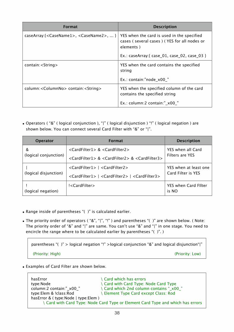
• Card Filter Functions are shown below.
Format Description
type:<CardType> YES when the card type is the specified card type( Card Type should be: “Node”, “Element” or “Elem”, “ElementProp”, or “ElemProp”, “Case”, “Restraint”, “Force”, “Null” )
Ex.: type:Elem
class:<CardClass> YES when the card class is the specified card class
Ex.: class:Hexa
hasError YES when the card type is Error Card Type or card has other errors
Ex.: hasError
case:<CaseName> YES when the card is used in the specified case( YES for all nodes or elements )
Ex.: case:case_01
37
Format Description
caseArray:{<CaseName1>, <CaseName2>, ... } YES when the card is used in the specified cases ( several cases ) ( YES for all nodes or elements )
Ex.: caseArray:{ case_01, case_02, case_03 }
contain:<String> YES when the card contains the specified string
Ex.: contain:”node_x00_”
column:<ColumnNo> contain:<String> YES when the specified column of the card contains the specified string
Ex.: column:2 contain:”_x00_”
• Operators ( “&” ( logical conjunction ), “|” ( logical disjunction ) “!” ( logical negation ) are shown below. You can connect several Card Filter with “&” or “|”.
Operator Format Description
&(logical conjunction)
<CardFilter1> & <CardFilter2>
<CardFilter1> & <CardFilter2> & <CardFilter3>
YES when all Card Filters are YES
|(logical disjunction)
<CardFilter1> | <CardFilter2>
<CardFilter1> | <CardFilter2> | <CardFilter3>
YES when at least one Card Filter is YES
!(logical negation)
!<CardFilter> YES when Card FIlter is NO
• Range inside of parentheses “( )” is calculated earlier.
• The priority order of operators ( “&”, “|”, “!” ) and parentheses “( )” are shown below. ( Note: The priority order of “&” and “|” are same. You can’t use “&” and “|” in one stage. You need to encircle the range where to be calculated earlier by parentheses “( )”. )
parentheses “( )” > logical negation “!” >logical conjunction “&” and logical disjunction“|”
(Priority: High) (Priority: Low)
• Examples of Card Filter are shown below.
hasError \ Card which has errorstype:Node \ Card with Card Type: Node Card Typecolumn:2 contain:”_x00_” \ Card which 2nd column contains “_x00_”type:Elem & !class:Rod \ Element Type Card except Class: RodhasError & ( type:Node | type:Elem ) \ Card with Card Type: Node Card Type or Element Card Type and which has errors
38
About Card Value Expression
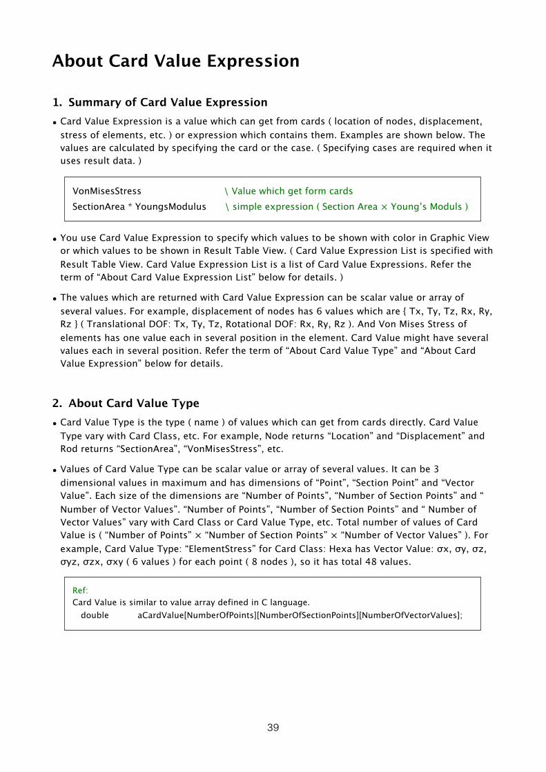
1. Summary of Card Value Expression• Card Value Expression is a value which can get from cards ( location of nodes, displacement,
stress of elements, etc. ) or expression which contains them. Examples are shown below. The values are calculated by specifying the card or the case. ( Specifying cases are required when it uses result data. )
VonMisesStress \ Value which get form cardsSectionArea * YoungsModulus \ simple expression ( Section Area × Young’s Moduls )
• You use Card Value Expression to specify which values to be shown with color in Graphic View or which values to be shown in Result Table View. ( Card Value Expression List is specified with Result Table View. Card Value Expression List is a list of Card Value Expressions. Refer the term of “About Card Value Expression List” below for details. )
• The values which are returned with Card Value Expression can be scalar value or array of several values. For example, displacement of nodes has 6 values which are { Tx, Ty, Tz, Rx, Ry, Rz } ( Translational DOF: Tx, Ty, Tz, Rotational DOF: Rx, Ry, Rz ). And Von Mises Stress of elements has one value each in several position in the element. Card Value might have several values each in several position. Refer the term of “About Card Value Type” and “About Card Value Expression” below for details.
2. About Card Value Type• Card Value Type is the type ( name ) of values which can get from cards directly. Card Value
Type vary with Card Class, etc. For example, Node returns “Location” and “Displacement” and Rod returns “SectionArea”, “VonMisesStress”, etc.
• Values of Card Value Type can be scalar value or array of several values. It can be 3 dimensional values in maximum and has dimensions of “Point”, “Section Point” and “Vector Value”. Each size of the dimensions are “Number of Points”, “Number of Section Points” and “ Number of Vector Values”. “Number of Points”, “Number of Section Points” and “ Number of Vector Values” vary with Card Class or Card Value Type, etc. Total number of values of Card Value is ( “Number of Points” × “Number of Section Points” × “Number of Vector Values” ). For example, Card Value Type: “ElementStress” for Card Class: Hexa has Vector Value: σx, σy, σz, σyz, σzx, σxy ( 6 values ) for each point ( 8 nodes ), so it has total 48 values.
Ref:Card Value is similar to value array defined in C language. double aCardValue[NumberOfPoints][NumberOfSectionPoints][NumberOfVectorValues];
39

Demension Description
Point It means position of values which vary by position on Element Card, etc. Usually it is node which form the element, but might be different when position for element stress are specified, etc.
Usually, cards except element cards don’t have the dimension ( Number of Points = 1 )
It might vary by Card Class or Card Value Type. Refer the term of the Card Class.
Expamle:On Card Value with Card Value Type: “VonMisesStress” for “Hexa”, Number of Points is 8 ( same as number of nodes which form the element ) and the value of each Point is Von Mises Stress on the node which forms the element (Hexa).
Section Point Usually, the dimension does not exist. ( Number of Section Points = 1 )
It means positions on one Point ( Node ) when several position for the value exist on one Point, such as ‘front face’/’back face’ of Quad ( shell element ).
It might vary by Card Class or Card Value Type. Refer the term of the Card Class.
Expamle:On Card Value with Card Value Type: “VonMisesStress@shellFace” for “Quad”, Number of Section Points is 2 ( and Number of Points is 4 ( same as number of nodes which form the element ) ) and the value of each Section Point is Von Mises Stress on front face / back face on the element.
Vector Value Number of Vector Values is fixed by Card Value Type. It doesn’t depend on Card ( Card Class, etc. ).
Example:Number of Vector Values for Card Value Type: “Displacement” is 6. ( Translational DOF: Tx, Ty, Tz, Rotational DOF: Rx, Ry, Rz )
Number of Vector Values for Card Value Type: “VonMisesStress”, “SectionArea” is 1 ( scalar value ).
Number of Vector Values for Card Value Type: “ElementStress” is 6 ( σx, σy, σz, σyz, σzx, σxy ).
• Card Value Type is specified by ( only ) Major Card Value Type ( “VonMisesStress”, etc. ), or combination of Major Card Value Type and Minor Card Value Type ( “@shellFace”, etc. ). In most of cases, only Major Card Value Type is used, but Minor Card Value Type is needed in some cases. For example, Stress on Quad element vary by faces ( front face/back face ), so to get ”ElementStress” ( σx, σy, σz, σyz, σzx, σxy ), you need to specify as “ElementStress@shellFace”. ( Also “VonMisesStress” on Quad element vary by faces, maximum ( bigger ) value of both faces is returned when just specified as “VonMisesStress”. ) ( Refer the term of each card classes. )
40

• Card Value Type which can get from cards depends on Card Class. Refer the term of each card class for Card Value Type for each card.
3. About Card Value Expression• Card Value Expression is an expression which contains Card Value Type, etc, and you can use
“+”(addition), “-”(subtraction), * (multiplication), / (division) or “( )” (parentheses). Examples are shown below. ( Only simple operations are implemented with current version. )
VonMisesStress \ One Card Value TypeSectionArea * YoungsModulus \ Expression with simple operation
• On operation with operator ”+”、“-”、“*”、“/”, each of “Number of Points”, “Number of Section
Points”, “Number of Vector Values” of Card Value on both side ( ahead, aback ) of the operator must be same value with other or must be 1. When it is 1 and other is not 1, the dimension of it will be expanded to the number of other, and each values in the dimension will be operated (”+”、“-”、“*”、“/” ) by each components.
4. About Card Value Expression List
• Card Value Expression List is a list of several Card Value Expressions. Card Filter can be specified to restrict cards. It is used to specify which values to be shown in Result Table View. Examples are shown below. ( Card Value Expression List can be several rows. “Example 2” below, 2 rows are one Card Value Expression List. )
\ Example 1\ Several Card Value ExpressionsVonMisesStress, RodForce;
\ Example 2\ Changes values to be shown by each cards with Card Filter\ ( Displacement when Card Type is Node / VonMisesStress when Card Type is Element )#(type:Node) : Displacement;#(type:Element) : VonMisesStress;
• Card Value Expression List is combination of two format below. The last character is semicolon ‘:’. You can input New-Line character at any location except inside of ’#( <Card Filter> ) :’ or inside of <Card Value Expression>. You can put several Card Value Expressions with separating by comma ‘,’.
\ Format 1 - No Card Filter<CardValueExpression-1>, <CardValueExpression-2>;
\ Format 2 - With Card Filter#( <CardFilter> ) : <CardValueExpression-1>, <CardValueExpression-2>;
41

• With “Format 1” ( No Card Filter ), all Card Value Expressions ( until semicolon ‘;’ ) are valid for any cards. With “Format 2” ( With Card Filter ), Card Value Expressions ( until semicolon ‘;’ ) are valid for cards which conform to the <Card Filter>. When several rows ( blocks which separated by ‘;’ ) exist, all Card Value Expressions which are valid in each block are valid.
42
Card Class
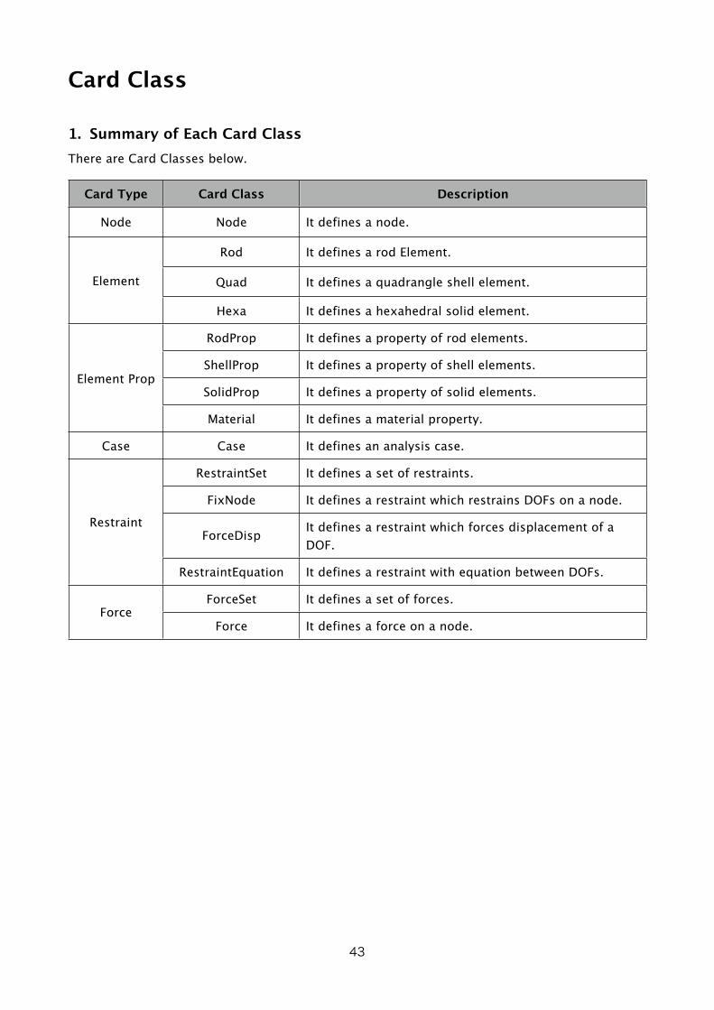
1. Summary of Each Card ClassThere are Card Classes below.
Card Type Card Class Description
Node Node It defines a node.
Element
Rod It defines a rod Element.
Quad It defines a quadrangle shell element.
Hexa It defines a hexahedral solid element.
Element Prop
RodProp It defines a property of rod elements.
ShellProp It defines a property of shell elements.
SolidProp It defines a property of solid elements.
Material It defines a material property.
Case Case It defines an analysis case.
Restraint
RestraintSet It defines a set of restraints.
FixNode It defines a restraint which restrains DOFs on a node.
ForceDisp It defines a restraint which forces displacement of a DOF.
RestraintEquation It defines a restraint with equation between DOFs.
ForceForceSet It defines a set of forces.
Force It defines a force on a node.
43

2. About Column TypeThere are several column types below. Every columns ( except 1st column for Card Class name ) on cards are one of them.
Column Type Description
Card Name
Card Name for the card ( Column No: 2 ) or used to specify other cards to refer.
Example:node_120_r60_40n0123456701234567
Real Number
Real Number Value. Used to specify values such as location of nodes, material property, forces.
Example:+12.34-0.123412.34E+06
Boolean Value
( BOOL )
Boolean Value. Used to specify YES ( “1” or “YES” ), NO ( “0” or “NO” ), such as ON / OFF of restraint in FixNode Card.
String for Column:For YES ( ON ) : “1” or “YES”For NO ( OFF ) : “0” or “NO”
DOF( Degree of Freedom )
DOF ( Degree of Freedom ). Used to specify DOF, such as DOF to be restrained. It is specified with Node Name and Direction ( Tx, Ty, Tz, Rx, Ry, Rz ) with character ‘@’ between the node name and the direction.
Example:node_01@TXnode_120_r60_40@RZ
StringUsed to specify string which is specified by card.
Example:LINEAR_STATIC
You can use characters ‘a-z’, ‘A-Z’, ‘0-9’, ‘_’ ( under-bar ), non-ASCII characters, etc. for Card Name. You can not use other ASCII characters ( !”#$%&’()*+,-./:;<=>?@[\]^`{|}~ or ‘ ‘(space character) ).
3. Each Card ClassAfter Next Page.
44

Node( Card Type: Node Card Type )
*Definition of Node*
\ FormatNode , <Node Name> , , <Location X> , <Location Y> , <Location Z> ,
\ ExampleNode , node_01 , , 100.0 , -20.0 , 50.0 ,
X
Y
Z
Node
Column No. Column Column Type Description
1 “Node” Card Class Name
2 <Node Name> Card Name Card Name of Node
3 Empty
4 <Location X> Real Number Location X
5 <Location Y> Real Number Location Y
6 <Location Z> Real Number Location Z
Description :
• It defines a node with Node Name: <Node Name>.
• <Node Name> is referred from Element Card, Force Card, Restraint Card.
Supported Card Value Type :
Major Card Value Type
Minor Card Value Type Size Description
Location <None> 1•1•3 Node Location{ X , Y , Z }
45

Major Card Value Type
Minor Card Value Type Size Description
Displacement <None> 1•1•6 Node Displacement{ Tx , Ty , Tz , Rx , Ry , Rz }
The “Size” is : <Number of Points>•<Number of Section Points>•<Number of Vector Values>.
46
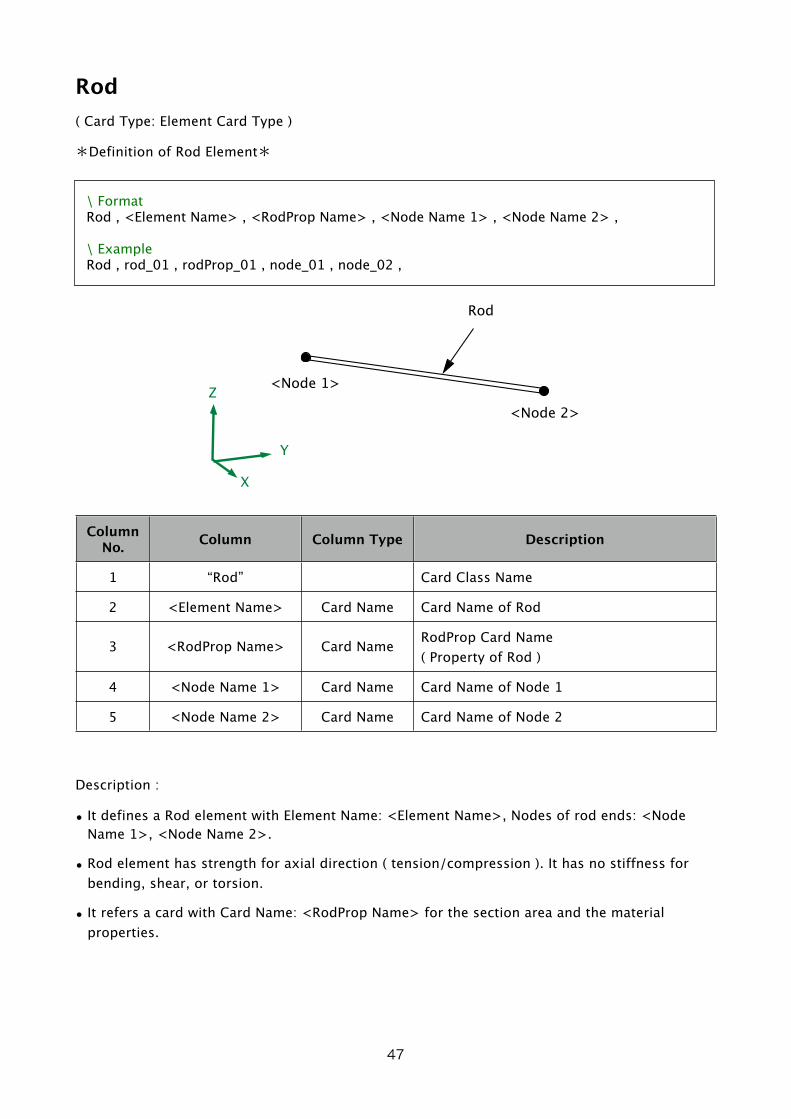
Rod( Card Type: Element Card Type )
*Definition of Rod Element*
\ FormatRod , <Element Name> , <RodProp Name> , <Node Name 1> , <Node Name 2> ,
\ ExampleRod , rod_01 , rodProp_01 , node_01 , node_02 ,
X
Y
Z<Node 1>
<Node 2>
Rod
Column No. Column Column Type Description
1 “Rod” Card Class Name
2 <Element Name> Card Name Card Name of Rod
3 <RodProp Name> Card Name RodProp Card Name( Property of Rod )
4 <Node Name 1> Card Name Card Name of Node 1
5 <Node Name 2> Card Name Card Name of Node 2
Description :
• It defines a Rod element with Element Name: <Element Name>, Nodes of rod ends: <Node Name 1>, <Node Name 2>.
• Rod element has strength for axial direction ( tension/compression ). It has no stiffness for bending, shear, or torsion.
• It refers a card with Card Name: <RodProp Name> for the section area and the material properties.
47

Supported Card Value Type :
Major Card Value Type
Minor Card Value Type Size Description
Length <None> 1•1•1 Rod Length( Distance between nodes )
SectionArea <None> 1•1•1 Rod Section Area
YoungsModulus <None> 1•1•1 Young’s Modulus : E
PoissonsRatio <None> 1•1•1 Poisson’s Ratio : ν
RodForce <None> 2•1•1
Force on RodAxial Force( + : tension / - : compression )( Calculated Position : Nodes )
VonMisesStress <None> 2•1•1 Von Mises Stress( Calculated Position : Nodes )
ElementStress <None> 2•1•6Stress in element{ σx, σy, σz, σyz, σzx, σxy }( Calculated Position : Nodes )
ElementStrain <None> 2•1•6Strain in element{ εx, εy, εz, εyz, εzx, εxy }( Calculated Position : Nodes )
ElementNodeForce <None> 2•1•6 Forces from each nodes{ Fx, Fy, Fz, Mx, My, Mz }
The “Size” is : <Number of Points>•<Number of Section Points>•<Number of Vector Values>.
• Coordinate System for Card Value Type “ElementStress”, “ElementStrain” is Element Coordinate System.
• Coordinate System for Card Value Type “ElementNodeForce” is Global Coodinate System.
• Element Coordinate System is that the direction of X axis is ahead from <Node 1> to <Node 2>. ( The direction of Y axis, Z axis are any direction which froms right-hand-system with X axis. )
• Values of Card Value Type “ElementStress” except σx are 0 (zero).
• On Card Value Type “ElementStrain”, εyz, εzx, εxy are 0 (zero) ,and εy = εz = -ν•εx. ( ν is Poisson’s Ratio )
48
Quad
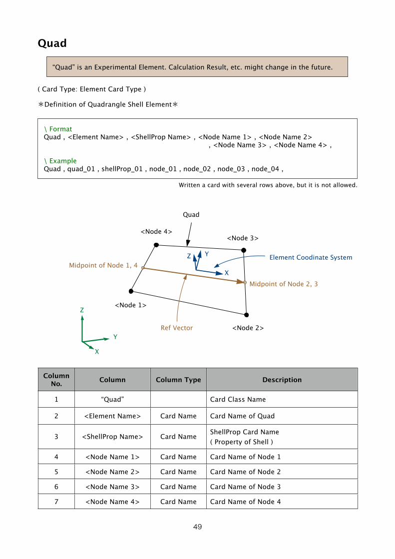
“Quad” is an Experimental Element. Calculation Result, etc. might change in the future.
( Card Type: Element Card Type )
*Definition of Quadrangle Shell Element*
\ FormatQuad , <Element Name> , <ShellProp Name> , <Node Name 1> , <Node Name 2> , <Node Name 3> , <Node Name 4> ,
\ ExampleQuad , quad_01 , shellProp_01 , node_01 , node_02 , node_03 , node_04 ,
Written a card with several rows above, but it is not allowed.
Midpoint of Node 2, 3
Midpoint of Node 1, 4
X
Y
Z<Node 1>
<Node 2>
<Node 4><Node 3>
Quad
Ref Vector
X
YZ Element Coodinate System
Column No. Column Column Type Description
1 “Quad” Card Class Name
2 <Element Name> Card Name Card Name of Quad
3 <ShellProp Name> Card Name ShellProp Card Name( Property of Shell )
4 <Node Name 1> Card Name Card Name of Node 1
5 <Node Name 2> Card Name Card Name of Node 2
6 <Node Name 3> Card Name Card Name of Node 3
7 <Node Name 4> Card Name Card Name of Node 4
49
Description :
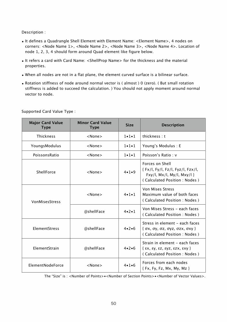
• It defines a Quadrangle Shell Element with Element Name: <Element Name>, 4 nodes on corners: <Node Name 1>, <Node Name 2>, <Node Name 3>, <Node Name 4>. Location of node 1, 2, 3, 4 should form around Quad element like figure below.
• It refers a card with Card Name: <ShellProp Name> for the thickness and the material properties.
• When all nodes are not in a flat plane, the element curved surface is a bilinear surface.
• Rotation stiffness of node around normal vector is ( almost ) 0 (zero). ( But small rotation stiffness is added to succeed the calculation. ) You should not apply moment around normal vector to node.
Supported Card Value Type :
Major Card Value Type
Minor Card Value Type Size Description
Thickness <None> 1•1•1 thickness : t
YoungsModulus <None> 1•1•1 Young’s Modulus : E
PoissonsRatio <None> 1•1•1 Poisson’s Ratio : ν
ShellForce <None> 4•1•9
Forces on Shell{ Fx/l, Fy/l, Fz/l, Fyz/l, Fzx/l, Fxy/l, Mx/l, My/l, Mxy/l }( Calculated Position : Nodes )
VonMisesStress
<None> 4•1•1Von Mises StressMaximum value of both faces( Calculated Position : Nodes )
@shellFace 4•2•1 Von Mises Stress - each faces( Calculated Position : Nodes )
ElementStress @shellFace 4•2•6Stress in element - each faces{ σx, σy, σz, σyz, σzx, σxy }( Calculated Position : Nodes )
ElementStrain @shellFace 4•2•6Strain in element - each faces{ εx, εy, εz, εyz, εzx, εxy }( Calculated Position : Nodes )
ElementNodeForce <None> 4•1•6 Forces from each nodes{ Fx, Fy, Fz, Mx, My, Mz }
The “Size” is : <Number of Points>•<Number of Section Points>•<Number of Vector Values>.
50

• Coordinate System for Card Value Type “ElementStress”, “ElementStrain” is Element Coordinate System.
• Coordinate System for Card Value Type “ElementNodeForce” is Global Coodinate System.
• Element Coordinate System in each location on surface is :( Ref Vector : Vector from <Midpoint of Node 1, 4> to <Midpoint of Node 2, 3> )
z-axis : Direction of normal vector of element surface. Positive direction is that right screw of Node 1, 2, 3, 4 toward.
x-axis : Perpendicularly to z-axis and in plane by z-axis and Ref Vector. Positive direction is close to Ref Vector direction.
y-axis : Direction of outer-product by z-axis and Ref Vector.
• Card Value Type “ElementStress”, “ElementStrain” are needed to specify Minor Card Value Type “@shellFace”.
• When Minor Card Value Type “@shellFace” is specified, “Section Point 1” is on the face of minus ( negative ) side of z-axis / “Section Point 2” is on the face of plus ( positive ) side of z-axis.
• Card Value Type “VonMisesStress” without Minor Card Value Type “@shellFace” is maximum value ( bigger value ) of both faces.
51

Hexa( Card Type: Element Card Type )
*Definition of Hexahedral Solid Element*
\ FormatHexa , <Element Name> , <SolidProp Name> , <Node Name 1> , <Node Name 2> , , <Node Name 3> , <Node Name 4> , <Node Name 5> , <Node Name 6> , <Node Name 7> , <Node Name 8> ,\ ExampleRod , rod_01 , rodProp_01 , node_01 , node_02 , node_03 , node_04 , node_05 , node_06 , node_07 , node_08 ,
Written a card with several rows above, but it is not allowed.
<Node 3>
<Node 5>
<Node 6>
<Node 4>
X
Y
Z
<Node 1>
<Node 2>
<Node 7>
<Node 8> Hexa
Column No. Column Column Type Description
1 “Hexa” Card Class Name
2 <Element Name> Card Name Card Name of Hexa
3 <SlidProp Name> Card Name SolidProp Card Name( Property of Solid )
4 <Node Name 1> Card Name Card Name of Node 1
5 <Node Name 2> Card Name Card Name of Node 2
6 <Node Name 3> Card Name Card Name of Node 3
7 <Node Name 4> Card Name Card Name of Node 4
8 <Node Name 5> Card Name Card Name of Node 5
52
Column No. Column Column Type Description
9 <Node Name 6> Card Name Card Name of Node 6
10 <Node Name 7> Card Name Card Name of Node 7
11 <Node Name 8> Card Name Card Name of Node 8
Description :
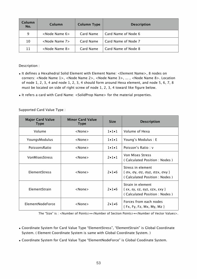
• It defines a Hexahedral Solid Element with Element Name: <Element Name>, 8 nodes on corners: <Node Name 1>, <Node Name 2>, <Node Name 3>, ... , <Node Name 8>. Location of node 1, 2, 3, 4 and node 1, 2, 3, 4 should form around Hexa element, and node 5, 6, 7, 8 must be located on side of right screw of node 1, 2, 3, 4 toward like figure below.
• It refers a card with Card Name: <SolidProp Name> for the material properties.
Supported Card Value Type :
Major Card Value Type
Minor Card Value Type Size Description
Volume <None> 1•1•1 Volume of Hexa
YoungsModulus <None> 1•1•1 Young’s Modulus : E
PoissonsRatio <None> 1•1•1 Poisson’s Ratio : ν
VonMisesStress <None> 2•1•1 Von Mises Stress( Calculated Position : Nodes )
ElementStress <None> 2•1•6Stress in element{ σx, σy, σz, σyz, σzx, σxy }( Calculated Position : Nodes )
ElementStrain <None> 2•1•6Strain in element{ εx, εy, εz, εyz, εzx, εxy }( Calculated Position : Nodes )
ElementNodeForce <None> 2•1•6 Forces from each nodes{ Fx, Fy, Fz, Mx, My, Mz }
The “Size” is : <Number of Points>•<Number of Section Points>•<Number of Vector Values>.
• Coordinate System for Card Value Type “ElementStress”, “ElementStrain” is Global Coordinate System. ( Element Coordinate System is same with Global Coordinate System. )
• Coordinate System for Card Value Type “ElementNodeForce” is Global Coodinate System.
53
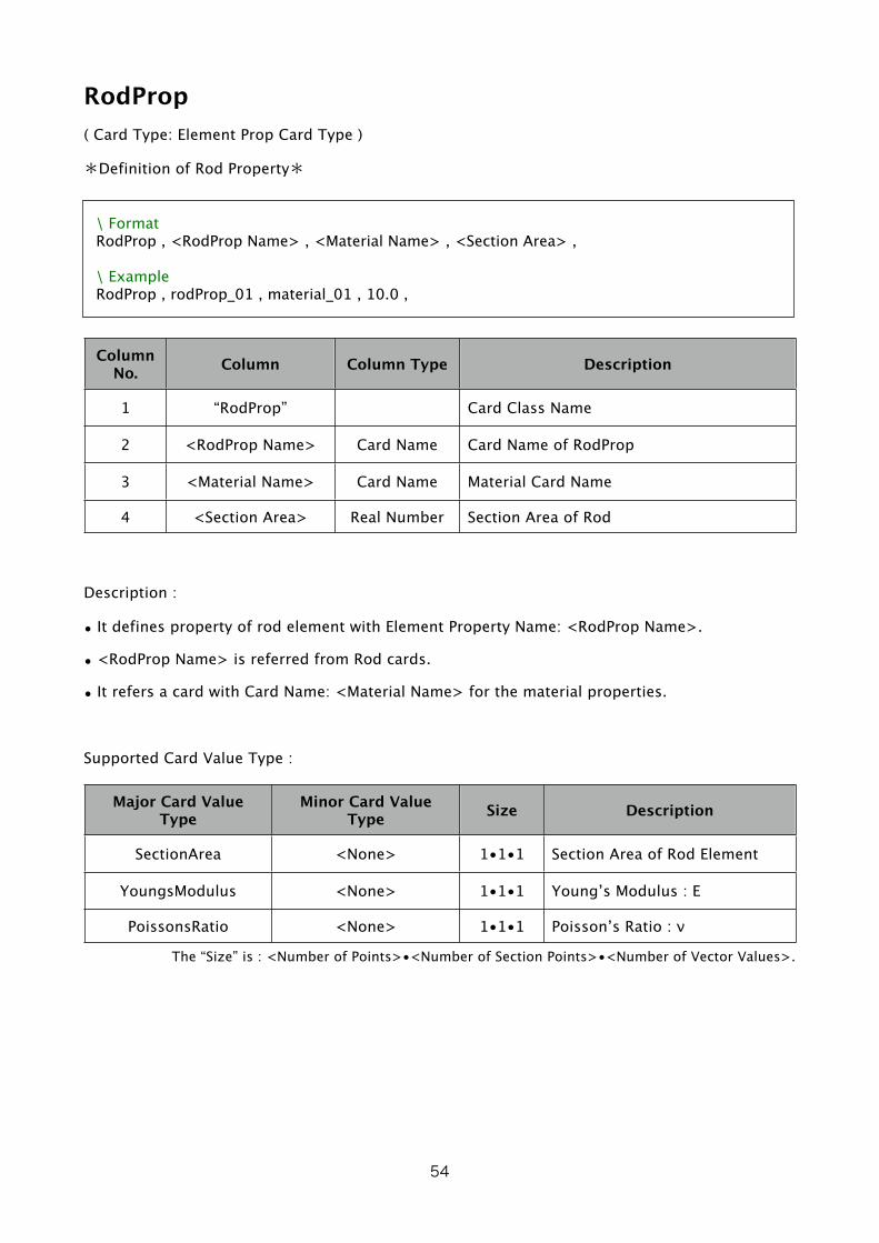
RodProp( Card Type: Element Prop Card Type )
*Definition of Rod Property*
\ FormatRodProp , <RodProp Name> , <Material Name> , <Section Area> ,
\ ExampleRodProp , rodProp_01 , material_01 , 10.0 ,
Column No. Column Column Type Description
1 “RodProp” Card Class Name
2 <RodProp Name> Card Name Card Name of RodProp
3 <Material Name> Card Name Material Card Name
4 <Section Area> Real Number Section Area of Rod
Description :
• It defines property of rod element with Element Property Name: <RodProp Name>.
• <RodProp Name> is referred from Rod cards.
• It refers a card with Card Name: <Material Name> for the material properties.
Supported Card Value Type :
Major Card Value Type
Minor Card Value Type Size Description
SectionArea <None> 1•1•1 Section Area of Rod Element
YoungsModulus <None> 1•1•1 Young’s Modulus : E
PoissonsRatio <None> 1•1•1 Poisson’s Ratio : ν
The “Size” is : <Number of Points>•<Number of Section Points>•<Number of Vector Values>.
54
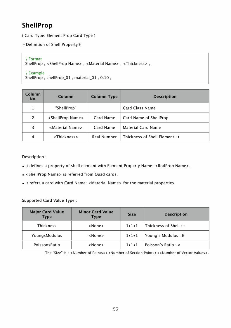
ShellProp( Card Type: Element Prop Card Type )
*Definition of Shell Property*
\ FormatShellProp , <ShellProp Name> , <Material Name> , <Thickness> ,
\ ExampleShellProp , shellProp_01 , material_01 , 0.10 ,
Column No. Column Column Type Description
1 “ShellProp” Card Class Name
2 <ShellProp Name> Card Name Card Name of ShellProp
3 <Material Name> Card Name Material Card Name
4 <Thickness> Real Number Thickness of Shell Element : t
Description :
• It defines a property of shell element with Element Property Name: <RodProp Name>.
• <ShellProp Name> is referred from Quad cards.
• It refers a card with Card Name: <Material Name> for the material properties.
Supported Card Value Type :
Major Card Value Type
Minor Card Value Type Size Description
Thickness <None> 1•1•1 Thickness of Shell : t
YoungsModulus <None> 1•1•1 Young’s Modulus : E
PoissonsRatio <None> 1•1•1 Poisson’s Ratio : ν
The “Size” is : <Number of Points>•<Number of Section Points>•<Number of Vector Values>.
55

SolidProp( Card Type: Element Prop Card Type )
*Definition of Solid Property*
\ FormatSolidProp , <SolidProp Name> , <Material Name> ,
\ ExampleSolidProp , solidProp_01 , material_01 ,
Column No. Column Column Type Description
1 “SolidProp” Card Class Name
2 <SolidProp Name> Card Name Card Name of SolidProp
3 <Material Name> Card Name Material Card Name
Description :
• It defines property of solid element with Element Property Name: <SolidProp Name>.
• <SolidProp Name> is referred from Hexa cards.
• It refers a card with Card Name: <Material Name> for the material properties.
Supported Card Value Type :
Major Card Value Type
Minor Card Value Type Size Description
YoungsModulus <None> 1•1•1 Young’s Modulus : E
PoissonsRatio <None> 1•1•1 Poisson’s Ratio : ν
The “Size” is : <Number of Points>•<Number of Section Points>•<Number of Vector Values>.
56

Material( Card Type: Element Prop Card Type )
*Definition of Material Property*
\ FormatMaterial , <Material Name> , <Youngs Modulus> , <Poissons Ratio> ,
\ ExampleMaterial , material_01 , 210.0E+09 , 0.3 ,
Column No. Column Column Type Description
1 “SolidProp” Card Class Name
2 <SolidProp Name> Card Name Card Name for Material
3 <Material Name> Real Number Young’s Modulus : E
4 <Poissons Ratio> Real Number Poisson’s Ratio : ν
Description :
• It defines material properties with Element Property Name: <Material Name>.
• <Material Name> is referred from ElementProp Card ( RodProp, ShellProp, SolidProp ).
Supported Card Value Type :
Major Card Value Type
Minor Card Value Type Size Description
YoungsModulus <None> 1•1•1 Young’s Modulus : E
PoissonsRatio <None> 1•1•1 Poisson’s Ratio : ν
The “Size” is : <Number of Points>•<Number of Section Points>•<Number of Vector Values>.
57
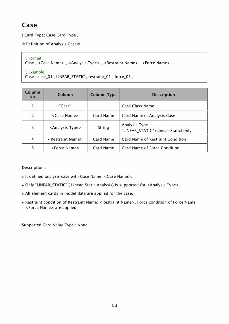
Case( Card Type: Case Card Type )
*Definition of Analysis Case*
\ FormatCase , <Case Name> , <Analysis Type> , <Restraint Name> , <Force Name> ,
\ ExampleCase , case_01 , LINEAR_STATIC , restraint_01 , force_01 ,
Column No. Column Column Type Description
1 “Case” Card Class Name
2 <Case Name> Card Name Card Name of Analysis Case
3 <Analysis Type> String Analysis Type“LINEAR_STATIC” (Linear-Static) only
4 <Restraint Name> Card Name Card Name of Restraint Condition
5 <Force Name> Card Name Card Name of Force Condition
Description :
• It defined analysis case with Case Name: <Case Name>.
• Only “LINEAR_STATIC” ( Linear-Static Analysis) is supported for <Analysis Type>.
• All element cards in model data are applied for the case.
• Restraint condition of Restraint Name: <Restraint Name>, Force condition of Force Name: <Force Name> are applied.
Supported Card Value Type : None
58
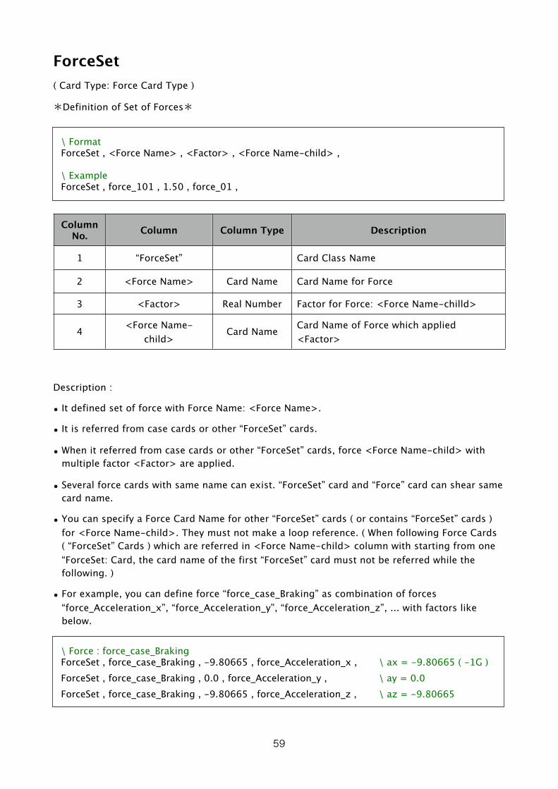
ForceSet( Card Type: Force Card Type )
*Definition of Set of Forces*
\ FormatForceSet , <Force Name> , <Factor> , <Force Name-child> ,
\ ExampleForceSet , force_101 , 1.50 , force_01 ,
Column No. Column Column Type Description
1 “ForceSet” Card Class Name
2 <Force Name> Card Name Card Name for Force
3 <Factor> Real Number Factor for Force: <Force Name-chilld>
4 <Force Name-child>
Card Name Card Name of Force which applied <Factor>
Description :
• It defined set of force with Force Name: <Force Name>.
• It is referred from case cards or other “ForceSet” cards.
• When it referred from case cards or other “ForceSet” cards, force <Force Name-child> with multiple factor <Factor> are applied.
• Several force cards with same name can exist. “ForceSet” card and “Force” card can shear same card name.
• You can specify a Force Card Name for other “ForceSet” cards ( or contains “ForceSet” cards ) for <Force Name-child>. They must not make a loop reference. ( When following Force Cards ( “ForceSet” Cards ) which are referred in <Force Name-child> column with starting from one “ForceSet: Card, the card name of the first “ForceSet” card must not be referred while the following. )
• For example, you can define force “force_case_Braking” as combination of forces “force_Acceleration_x”, “force_Acceleration_y”, “force_Acceleration_z”, ... with factors like below.
\ Force : force_case_BrakingForceSet , force_case_Braking , -9.80665 , force_Acceleration_x , \ ax = -9.80665 ( -1G )ForceSet , force_case_Braking , 0.0 , force_Acceleration_y , \ ay = 0.0ForceSet , force_case_Braking , -9.80665 , force_Acceleration_z , \ az = -9.80665
59

Supported Card Value Type : None
60

Force( Card Type: Force Card Type )
*Definition of Force on Node*
\ FormatForce , <Force Name> , <Node Name> , , <Fx> , <Fy> , <Fz> , <Mx> , <My> , <Mz> ,
\ ExampleForce , force_01 , node_01 , , 100.0 , 200.0, -300.0 , , , ,
Column No. Column Column Type Description
1 “Force” Card Class Name
2 <Force Name> Card Name Card Name of Force
3 <Node Name> Card Name Node Card Name to be forced
4 Empty
5 <Fx> Real Number Force : Fx
6 <Fy> Real Number Force : Fy
7 <Fz> Real Number Force : Fz
8 <Mx> Real Number Moment : Mx
9 <My> Real Number Moment : My
10 <Mz> Real Number Moment : Mz
Description :
• It defines node force with Force Name: <Force Name>.
• It is referred from Case Card, or “ForceSet” Card.
• Force Fx, Fy, Fz, Mx, My, Mz are applied on node <Node Name>. You can make the Fx ~ Mz
columns empty for 0.0 (zero).
Supported Card Value Type : None
61

RestraintSet( Card Type: Restraint Card Type )
*Definition of Set of Restraint*
\ FormatRestraintSet , <Restraint Name> , <Restraint Name-child> ,
\ ExampleRestraintSet , restraint_101 , restraint_01 ,
Column No. Column Column Type Description
1 “RestraintSet” Card Class Name
2 <Restraint Name> Card Name Card Name of Restraint
3 <Restraint Name-child>
Card Name Restraint Card Name applied
Description :
• It defines restraint with Restraint Name: <Restraint Name>.
• It is referred from case cards or other “RestraintSet” cards.
• When it referred from case cards or other “RestraintSet” cards, restraint <Restraint Name-child> are applied.
• Several restriant cards with same name can exist. “RestraintSet” card, “FixNode” card, “RestraintEquation” card, etc. can shear same card name.
• You can specify a Restraint Card Name for other “RestraintSet” cards ( or contains “RestraintSet” cards ) for <Restraint Name-child>. They must not make a loop reference. ( When following Restraint Cards ( “RestraintSet” Cards ) which are referred in <Restraint Name-child> column with starting from one “RestraintSet: Card, the card name of the first “RestraintSet” card must not be referred while the following. )
• For example, you can define restraint “restraint_101” as combination of restraints “restraint_01”, “restraint_02” , “restraint_03” like below.
\ Restraint : restraint_101RestraintSet , restraint_101 , restraint_01 , RestraintSet , restraint_101 , restraint_02 , RestraintSet , restraint_101 , restraint_03 ,
Supported Card Value Type : None
62

FixNode( Card Type: Restraint Card Type )
*Definition of Restraint Node*
\ FormatFixNode , <Restraint Name> , <Node Name> , <Flag Tx> , <Flag Ty> , <Flag Tz> , <Flag Rx> , <Flag Ry> , <Flag Rz> ,
\ ExampleFixNode , restraint_01 , node_01 , 1 , 1 , 1 , 0 , 0 , 0 ,
Written a card with several rows above, but it is not allowed.
Column No. Column Column Type Description
1 “FixNode” Card Class Name
2 <Restraint Name> Card Name Card Name of Restraint
3 <Node Name> Card Name Node Card Name which is restrained
4 <Flag Tx> Boolean Value Whether restrains DOF Tx of node
5 <Flag Ty> Boolean Value Whether restrains DOF Ty of node
6 <Flag Tz> Boolean Value Whether restrains DOF Tz of node
7 <Flag Rx> Boolean Value Whether restrains DOF Rx of node
8 <Flag Ry> Boolean Value Whether restrains DOF Ry of node
9 <Flag Rz> Boolean Value Whether restrains DOF Rz of node
Description :
• It defines a restraint on node with Restraint Name: <Restraint Name>.
• It is referred from case cards or “RestraintSet” cards.
• It restrains DOF ( Degree of Freedom ) Tx, Ty, Tz, Rx, Ry, Rz of node <Node Name> by flags <Flag Tx>, <Flag Ty>, <Flag Tz>, <Flag Rx>, <Flag Ry>, <Flag Rz>. To restrain the DOF, set “YES” or “1” to <Flag ??> column. To not restrain the DOF, set “NO” or “0” to <Flag ??> column or make the column empty.
• One DOF must not be restrained by several Restraint Cards ( 2 or more ) in one analysis case. But it can be restrained by several “FixNode” cards ( no other restraint cards ). It means that a DOF which is restrained by a “FixNode” in an analysis case can be restrained by other “FixNode” cards, but can not be restrained by other “ForceDisp” or “RestraintEquation” cards in the analysis case.
63

Supported Card Value Type : None
64
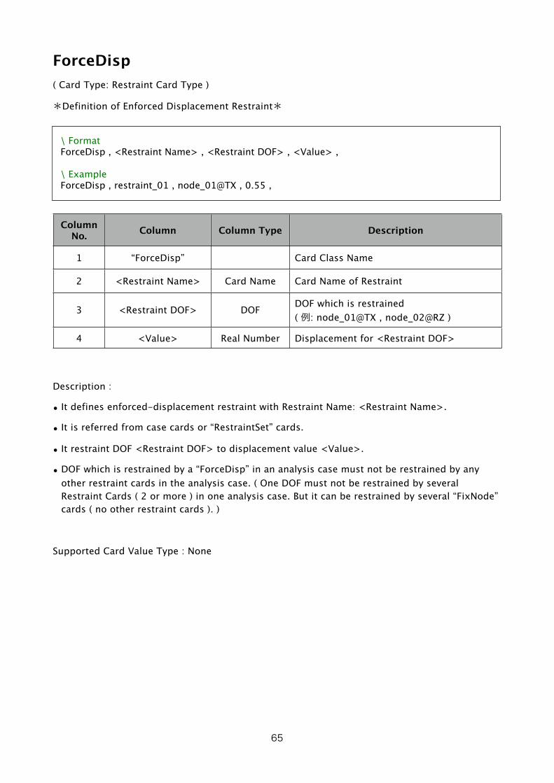
ForceDisp( Card Type: Restraint Card Type )
*Definition of Enforced Displacement Restraint*
\ FormatForceDisp , <Restraint Name> , <Restraint DOF> , <Value> ,
\ ExampleForceDisp , restraint_01 , node_01@TX , 0.55 ,
Column No. Column Column Type Description
1 “ForceDisp” Card Class Name
2 <Restraint Name> Card Name Card Name of Restraint
3 <Restraint DOF> DOF DOF which is restrained( 例: node_01@TX , node_02@RZ )
4 <Value> Real Number Displacement for <Restraint DOF>
Description :
• It defines enforced-displacement restraint with Restraint Name: <Restraint Name>.
• It is referred from case cards or “RestraintSet” cards.
• It restraint DOF <Restraint DOF> to displacement value <Value>.
• DOF which is restrained by a “ForceDisp” in an analysis case must not be restrained by any other restraint cards in the analysis case. ( One DOF must not be restrained by several Restraint Cards ( 2 or more ) in one analysis case. But it can be restrained by several “FixNode” cards ( no other restraint cards ). )
Supported Card Value Type : None
65

RestraintEquation( Card Type: Restraint Card Type )
*Definition of Restraint Equation ( Equation between DOFs )*
\ Format ( You can add/remove columns after pair of <Value 2>, <DOF 2>. )RestraintEquation , <Restraint Name> , <Value> , <Restraint DOF> , <Value 1> , <DOF 1> , [ <Value 2> , <DOF 2> , <Value 3> , <DOF 3> , ... , <Value N> , <DOF N> , ]
\ ExampleRestraintEquation , restraint_01 , -10.0 , node_02@TX , +4.0 , node_01@TX , +6.0 , node_03@TX ,
Written a card with several rows above, but it is not allowed.
Column No. Column Column Type Description
1 “RestraintEquation” Card Class Name
2 <Restraint Name> Card Name Card Name of Restraint
3 <Value> Real Number Factor for <Restraint DOF>
4 <Restraint DOF> DOF DOF which is restrained( Dependent DOF )
5 <Value 1> Real Number Factor for <DOF 1>
6 <DOF 1> DOF Independent DOF 1
7 <Value 2> Real Number Factor for <DOF 2> ( Optional )
6 <DOF 2> DOF Independent DOF 2 ( Optional )
•••
<Value N> Real Number Factor for <DOF N> ( Optional )
<DOF N> DOF Independent DOF N ( Optional )
Description :
• It defined restraint equation ( equation between DOFs ) with Restraint Name: <Restraint Name>.
• It is referred from case cards or “RestriantSet” cards.
• Dependent DOF <Restraint DOF> is applied a linear equation by N counts ( N is equal to or bigger than 1 ) of Independent DOFs ( <DOF 1> ~ <DOF N> ) and the Dependent DOF
<Restraint DOF> is removed from global stiffness equation. Columns after pair of <Value 2>,
66
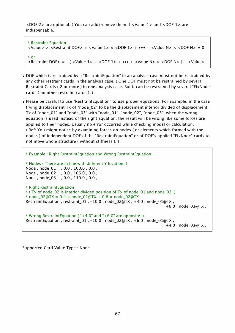
<DOF 2> are optional. ( You can add/remove them. ) <Value 1> and <DOF 1> are indispensable.
\ Restraint Equation<Value> × <Restraint DOF> + <Value 1> × <DOF 1> + ••• + <Value N> × <DOF N> = 0
\ or<Restraint DOF> = - ( <Value 1> × <DOF 1> + ••• + <Value N> × <DOF N> ) ÷ <Value>
• DOF which is restrained by a “RestraintEquation” in an analysis case must not be restrained by any other restraint cards in the analysis case. ( One DOF must not be restrained by several Restraint Cards ( 2 or more ) in one analysis case. But it can be restrained by several “FixNode” cards ( no other restraint cards ). )
• Please be careful to use “RestraintEquation” to use proper equations. For example, in the case trying displacement Tx of “node_02” to be the displacement interior divided of displacement Tx of “node_01” and “node_03” with “node_01”, “node_02”, “node_03”, when the wrong equation is used instead of the right equation, the result will be wrong like some forces are applied to their nodes. Usually no error occurred while checking model or calculation.( Ref: You might notice by examining forces on nodes ( or elements which formed with the nodes ) of independent DOF of the “RestraintEquation” or of DOF’s applied “FixNode” cards to not move whole structure ( without stiffness ). )
\ Example : Right RestraintEquation and Wrong RestraintEquation
\ Nodes ( There are in line with different Y location. )Node , node_01 , , 0.0 , 100.0 , 0.0 , Node , node_02 , , 0.0 , 106.0 , 0.0 , Node , node_03 , , 0.0 , 110.0 , 0.0 ,
\ Right RestraintEquation\ ( Tx of node_02 is interior divided position of Tx of node_01 and node_03. )\ node_02@TX = 0.4 × node_01@TX + 0.6 × node_02@TXRestraintEquation , restraint_01 , -10.0 , node_02@TX , +4.0 , node_01@TX , +6.0 , node_03@TX ,
\ Wrong RestraintEquation ( “+4.0” and “+6.0” are opposite. )RestraintEquation , restraint_01 , -10.0 , node_02@TX , +6.0 , node_01@TX , +4.0 , node_03@TX ,
Supported Card Value Type : None
67

Miscellaneous Functions1. About Tool - Merge Nodes on Same Location
• It merges several nodes which are on same location ( or the distance is smaller than specified length ) from selected nodes. ( Several nodes exist at one location, one node will be remained and others will be removed. ) The referring node name of removed node in element cards, force cards, restraint cards will be changed to the remained node name.
• Input distance between nodes to be judged as same location in “Node Merge Distance” text field.
• You can choose which nodes ( nodes on above or nodes on below in model data’s index ) in several nodes on same location with “Option” popup menu : “Keep Node Above” / “Keep Node Below”. Or when “Use Node Name List to Keep in Clipboard” check button is checked, nodes in clipboard will be remained. Copy card name list ( card name list table which is separated with New-Line character or comma character ) to clipboard before push “Apply”.
• With “Write List to Clipboard” button, nodes list on same location is written to clipboard. Node card names in same row in written text are nodes which are on same location, and the left node of them will be remained when you push “Apply” button. You can check which nodes are merged before execute.
• With “Apply” button, the nodes are merged and the merged node name list ( same as text which is written when “Write List to Clipboard” button pushed ) will be written to clipboard.
• You can make model text of complex model by several simple separated zone with same node location on the zone boundary and then you can merge the nodes on the boundary with this function.
68
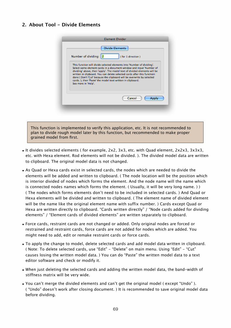
2. About Tool - Divide Elements
This function is implemented to verify this application, etc. It is not recommended to plan to divide rough model later by this function, but recommended to make proper grained model from first.
• It divides selected elements ( for example, 2x2, 3x3, etc. with Quad element, 2x2x3, 3x3x3, etc. with Hexa element. Rod elements will not be divided. ). The divided model data are written to clipboard. The original model data is not changed.
• As Quad or Hexa cards exist in selected cards, the nodes which are needed to divide the elements will be added and written to clipboard. ( The node location will be the position which is interior divided of nodes which forms the element. And the node name will the name which is connected nodes names which forms the element. ( Usually, it will be very long name. ) ) ( The nodes which forms elements don’t need to be included in selected cards. ) And Quad or Hexa elements will be divided and written to clipboard. ( The element name of divided element will be the name like the original element name with suffix number. ) Cards except Quad or Hexa are written directly to clipboard. “Cards written directly” / “Node cards added for dividing elements” / “Element cards of divided elements” are written separately to clipboard.
• Force cards, restraint cards are not changed or added. Only original nodes are forced or restrained and restraint cards, force cards are not added for nodes which are added. You might need to add, edit or remake restraint cards or force cards.
• To apply the change to model, delete selected cards and add model data written in clipboard. ( Note: To delete selected cards, use “Edit” - “Delete” on main menu. Using “Edit” - “Cut” causes losing the written model data. ) You can do “Paste” the written model data to a text editor software and check or modify it.
• When just deleting the selected cards and adding the written model data, the band-width of stiffness matrix will be very wide.
• You can’t merge the divided elements and can’t get the original model ( except “Undo” ). ( “Undo” doesn’t work after closing document. ) It is recommended to save original model data before dividing.
69
Miscellaneous
1. About Band-Width of Stiffness Matrix, etc.Node: This information is about Load Design ver.0.8.1.5. It might change in future.
• With Load Design ver.0.8.1.5, though it is under development, node ordering function ( ordering nodes in global stiffness matrix ) implemented. It affects band width of global stiffness matrix and narrower band width makes memory footprint smaller and calculation time shorter. ( Planning to continue developing this function. )
• Calculation Cases with same restraint ( Case Cards which specify same restraint card name ) calculate together in stiffness equation. But cases with same restraint don’t need to be continuously in model data. Cases with same restraint will be gathered when calculation even cases with other restraint exist between them.
• Stiffness equation calculation is calculated with IEEE 754 - 64bit ( double-precision floating-point arithmetic ).
70

About Support
1. About Support
Please refer the Web Page http://www.load-design.com/.
71

Change Log
• 2009/2/17 : Load Design version 0.8 Users Manual ( Japanese Language )
• 2009/5/20 : Load Design version 0.8 Users Manual ( English Language ) ( ver 0.8.0.3 )
• 2009/7/7 : Added notes for change displaying Restraints and Forces. ( ver 0.8.1 )
• 2011/8/10 : Fixed mistakes in a sample model data. ( ver 0.8.1.4.2 )
• 2011/10/5 : Changes about node ordering and calculation case order. ( page 70, etc. ) ( ver 0.8.1.5 )
72