Embed Size (px)
Citation preview

't) n i Lc t{.\' ta Lcs of I n e i ca
(D ep a rtm e t ú of lron s p o rt atio n(F e leraf A.uiation fl {m inßtration.
S rpp fementø [ Í1p e C ertific øt e
llfum[ter s¡ro682SC
Ifüs certficøte issuelto: IlartzclI l')nginc 'l'cchnologics I.l.(ì
2900 ScLna IIighr.vay
Montgomcry, Â1. 36108
certifies tliat tfre cliange in tfie tlpe lesignfor tlie foffowing proluct witñ tñe fitnitøtiotts ønl confitions tlierefore
øs specifie[ftereonmeets tfre airwortñiness requùcments of cPart 3of tfie Civit nir fugufations,
Original Product T¡pe Certilicate Nunrber: (See attached lìÂr\ Approvcd Model
Make: I-ist (AML) lor nrodels andModel: applicable airworthincss regulations)
Master Drawing ListNo. l4-0000. Rev. A, dated July 19,2007, or laterAI--MS 001, Rev. IR, dated July 25,2007 or AFMS 002, Rev. lR, dated
Li mitations and Conditions:The installer must determine rvhether this design change is compatible with previously approved modifications. If the holder agrees to permitanother person to use this ceftificate to alter a product, the holder must give the other person written evidence olthat perrnission.
Ífüs certficøte ønl the supporting lata wfücfi is tñe 6asis for øpprova[ sfraff remøin in ffict untif surrenferel,suspenlel, anl reaof,g[ or a terminntion late ß otñerwise esta\fishel fu tñe fllministrøtor of tfie Çeleraf,4 p in tio n A [min is L ra Lion.
Date reissued: 091 19107 : I I I 16107 ; 07 I l7 I I 4
Date amended:
ß1 lire ction of t ñe fl lministrator
Description of Type Design Change:Installation ofalternator and voltage regulator in accordance rvithFAA apploved revision. FAA approvecl Airplane Flight Manual,July 25, 2007, or later FAA approved revision is required.
Date of application: February 28, 2007
Date ofissuance: July 25,2007
litteManager, Aircraft Certification Offi ce,
Southwest Region
Anyalterationofthiscertificateispunishablebyafineofnotexceeding$l,000,orimprisonmentnotexceeding3years,orboth Thiscertificatemaybetranslerredormade available to third persons by ìicensing agreements in accordance with l4 CFR 21 47 Possession ofthis Supplemental Type Certificate (STC) document bypersonsotherthantheSTCholderdoesnotconstituterightstothedesigndatanortoalteranaircraft,aircraftengine,orpropeller TheSTC'ssupportingdocumentation (drawings, instructions, specifications, flight rnanual supplements, etc ) is the property ofthe STC holder An STC holder who allows a person to use
the STC to alter an aircraft, aircraft engine, or propeller must provide that person w¡th written permission acceptable to the FAA (Ref. I 4 CFR 2l 120)
FM Form 81,10-2 (8i13) Page 1

FAA APPROVIlD MODrir, r,tS',t' (^Mr_)
SAI0682SC
Date ofissuancc: July 25,2007
Hartzell Engine'l-cchnologics Ll,C2900 Sehna FliglrrvayMontgomery, At. 36108
Item Aircrall/llnginc Makc Âircrall/lìnginc Modcl Original'l'),pc
CclLifìcatcNt¡rnbcr
Iìcgu lation/Palt
Raltheon Ailcrafi Co. 35. ^35,
835. C35. D35. Iì35. tì35. C35. 35R.rnodilìccl by S'l'C convclsion to 0-470 or IO-470 ensinc.
^-777('Atì 3
llawkel' Beechcralì Corp. Bcech I I35, J35. K35, M35. N35. P35. 35-33.35-433. 35-833. 35-C33
3^15 CAIì 3
Alexandria Aircralt LLC Bellanca 14-19-2. l4-19-3. l4-19-3A tA3 CA]{ 3Cessna Aircralt Co. 180, r80A, 1808,180c, t80D.180Il, t80F.
I 80C546 CAIì 3
Cessna Aircralt Co. 182,t82A,1828, t82C, 182D, t820, t82F,r82G, l82H
3A t3 CAIì 3
Cessna Aircraft Co. t85. t85A. t858. 185C. l85D 3A24 CAIì 3Cessna Ailcraft Co. 2t0, 2t0A. 2 I 0-5 (205), 210-5A (205A) 3A2l CAR 3Cessna Aircraft Co. 206. P206 A4CE CAR 3Lockheed AircraftInternational
402-2 2All CAR 3
Prop-Jets Inc Meyers 200, 2004. 2008. 200C. 200D 3At8 CAR 3Sierra Hotel Aero, Inc. Navion D, E, F, G, H and Navion (L-l7A),
Navion A (L-l7A & L-l7B), B modified bySTC conversion to 0-470 or IO-470
/.782 CAR 3
Raytheon Aircraft Co. Beech 23 AICE CAR 3Revo. Inc Colonial C1, Colonial C2, Lake LA-4,LA-4A,
LA-4PAI A3 CAR 3
Alliance Aircraft Group,LLC
Helio H-250 lA8 CAR 3
Aircraft Parls &Development
Intermountain (Callair) A, A-2, A-4, A-5, A-5T, A-9, A-98
A-758 CAR 4aCAR 8
FS 2003 corporation Piper PA-12. PA-l2S A-780 CAR 3The New Piper Aircraft. lnc. Pioer PA- I 6. PA- l65 rAl CAR 3The New Piper Aircrall, Inc. Piper PA- 1 8, PA- I 85, PA- l8 " l 05" (Special),
PA-185 "105" (Special). PA-l95tA2 CAR 3
The New Piper Aircraft, Inc. PA18A. PA-18 "125" (Army L-214), PA-185"125", PA-184S "r25", pA-18'.135", (ArmyL-218), PA-I 8A "I 35", pAl 85',I 35",PAI8AS "I35", pA-18 ,,I50", pA-I8A',I50",PA-185 "150", pA-l8AS',150", pA-19,(Army L-18C), (When modified with FAAapproved rear mounted oil cooler.)
tA2 CAR 3
The New Piper A lcrall, Inc. PA-20-" I I 5". PA-20S-"1 I 5" tA4 CAR 3The New Piper Aircraft Inc. Piper PA-20, PA-20S, PA-20-"135", PA-20S-
"135'' (When modified with FAA approvedrear mounted oil cooler.)
tA4 CAR 3
The New Pioer Aircraft Inc. PA-22-108 lA6 CAR 3The New Piper Ailcrafì lnc Pipet P A-22, P A-22-13 5, PA-22S- I 35, PA-
22-1 50, PA-22S- I 50. p A-22- I 60, pA-22S- I 60tA6 CAR 3

(Whcn rnodifìcd rvith l¡ÂÂ approved rearmountcd oil coolcr.)
The New Piper Aircralt, Inc. P ipcr PA-24, P
^-24-250, l, A-24 -260, l, A-24-
400rA5 cAfì 3
Latinoamerica De Aviacion(Lavia) S.A.
Piper PA-25, P A-25 -23 5, P A-25 -260 2A8 CAII3
The New Piper Aircraft, Inc. Piper PA-28-140, PA-28-150, PA-2tl-160,PA-28-l 80, PA-28-235, pA-28S- I 60, pA-28S- I 80
2Al3 CAR 3
Moonev M2O, M2OA, M2OB, M2OC, M2OD, M2OE,M2OF. M2OG
2A3 CAR 3
Alliance Aircraft Group,LLC
Helio 500 A2EA CAR 3
KWAD Co. Super-V A5IN CAR IOThe New Piper Aircraft, Inc. Piper PA-23, PA-23- I 60, P A-23 -23 5, I> A-23 -
250,P4-F,23-250lAl0 CAR 3
The New Piper Aircrafl, Inc. Piper PA-30 AIEA CAR 3Cessna Aircraft Co. Cessna 3 10, 3104, 3108, 3 l0C, 3 l0D, 3 l0E,
3 t0F, 3 l0G, 3r0H, 310r, 310J, 3l0K3A l0 CAR 3
Twin Commander AircraÍÌCoroo¡ation
500A 6Al CAR 3
Hawker Beechc¡aft Co. Beech Baron 95-55, 95-455, 95-855, 95-B55A
3Al6 CAR 3
Fred Garcia Camair 480 2A2 CAR 3Hawker Beechcraft Co. Beech Travelair 95. B95. 8954. D954. E95 3At6 CAR 3
Twin Commander AircraftCorporation
500, 5008, 500u 6Ar CAR 3
FAA Appro
Date: July 17,2014
Manager, Aircraft Certifrcation Offi ce
Southwest Region

RE\ Date ny Kevtstons
F 9/l 8/08 SJK JPDATED DWG. ,I2-1001 REV. F
G 11119109 BRJUpdated 14-2001 Rev C, 14-300'l Rev B, 14-4001 Rev B, 14-5001 Rev B, 14-600Rev C, Removed Airplane Make and Model Eligibility, 12-1010,12-1001, AddedR1224
H 9t11t14 BRJ1)FIRST RELEASE OF DRAWINGS INTO HARTZELL DESIGN DATA 2)UPDATED14-2001 REV D, 14-3001 REV C, 14-4001 REV C, 14-5001 REV C, 14-6001 REV D
AND ADDED 10.1031 3) HEADING WAS "PLANE POWER LTD "
J 5129115 CMB1)ADDED 10-8099-1;2)ADDED MISSING PARTS TO BOMS; 3)CHANGED BOMOF 10-5051; 4) REMOVED LABEL AND LAMP LINES; 5)ADDED12-102't LtNE
Hartzell Engine Technologies l.¿CBelt Driven Aircraft Engine Alternator Conversion Parts List
MDL DRAWING I4.OOOO REV. J
Created: 3126107 Last Revised:5/29l15
MOUNTING KITS10-8099 H 5113115 Mountinq Kit 2 1
1 0-8099-1 \E\A 5t2Sh5 Mountino Kit 2
10-1012 F 10t24t14 TENSION ARM 1
1 0-1 009 F 10t3t14 PIVOT HOLE SPACER BUSHING 1
1 0-8003 H 10124114 BRACKET.LYC. 1
1 0-1 002 G 1013114 STARTER STRAP 1
1 0-1 003 E 1013114 U BRACKET 1
14-1011 NE\A 4t14t't5 28V ALTERNATOR INOPERATIVE LAMP I1 0-1 033 \E\A 2t2t15 TERMINAL, RING IAN5H-5A BOLT I4N960-516 /VASHER 1
AN7.42A BOLT 1
4N960-716 /VASHER 1
4N363-720 NUT 1
m1 0-90994 B 2t18t15 lVlountinq Kit 2
I 0-90044 A 9t8t14 ]ONTINENTAL TENSION ARM 1
1 0-90054 A 9t8t14 SPACER 3
1 0-90058 A 918114 SPACER 1
AN7-1OA 3OLT 1
MS35338-47 -OCKWASHER 2
4N960-516 /YASHER 2
AN5H-74 3OLT 1
MS20074-05-1 2 BOLT 1
AN7-434 BOLT 1
M521045-6 NUT 1
4N960-616 WASHER 2
AN6-41A BOLT 1
MS35338-45 LOCKWASHER 1
4N960-8161 WASHER 1
1 0-1 009 F 10t3t14 PIVOT HOLE SPACER BUSHING 1
10-3012 E 10t10t14 SPACER 1
1 0-9006 B 10t24t14 SUPPORT BRACKET 1
1 0-3009 G 10t10t14 PIVOT HOLE REAR SPACER BUSHING 1
I 0-301 0 F 10110114 PIVOT HOLE FRONT SPACER 1
Part No. Rev Date Descri
ol\+NJL
ol\NJL
oF-çNJL
oÈ-NJ
olrN
J
ALLA'14-2001 D 9t08t14 T AL24-7 0C lnstallation lnstructions 1
14-3001 c 9t10t14 TAL12-70 lnstallation Instructions 1
14-4001 c 9110114 T AL24-7 0 lnstallation lnstructions 1
14-5001 c 9110114 SALl 2-70 lnstallation lnstructions 1
14-6001 D 9110114 SALí 2-70C lnstallation lnstructions 1
User is responsible for verification of current revision before using this document. Document considered
"reference only" if not the current revision.

1 0-9003 K 10127114 ]RACKET TCM 1
4N363-624 !UT 1
14-1011 NE\A 4t14t15 28V ALTERNATOR INOPERATIVE LAMP 1
1 0-1 033 NE\A 2t2t15 TERMINAL, RING I
1 0-9007 6/1 0/08 BRACKET ASSEMBLY (AS REQUIRED) 2
1 0-90074 6/'10/08 BRACKET (AIR INDUCTION) 1
1 0-90078 6/l 0/08 BRACKET (ENGINE) 1
1 0-9007c 6/1 0/08 BRACKET 1
AN3-64 BOLT 4
AN3-54 BOLT 3
4N960-'10 WASHER 14
M521045-3 NUT 7
ALTERNATORS
1 0-1 050c E 3t31t't5Alternator Assy. 12 Volt / 3" DIA 3/8"V-BELT Pullev
1
1 0-1 051 F 1129115Aternator Assembly, 12Yoll I 112"
V-Belt Pulley2 1
r0-5050c D 2t18t15Aternator Assy. 24 Volt / 3" DIA 3/8"V-BELT Pullev
2
1 0-5051 c 5126115Aternator Assembly, 24Yolt I 112"
V-Belt Pullev2
1 0-5006 A 10110114 24V ALTERNATOR ASSEMBLY 1
10-1032 NE\^ 2t2t15 NUT. M5X.8 1
1 0-2005 F 11t3t14 1/2'V-BELT PULLEY 1
'10-1031 \EVl 915114 LABELc10-221 \E\A 2t2t15 SAFETY WIRE AR
PLACARDS14-1012 A 10t28t14 SINGLE ENGINE PLACARDS 1
14-10't3 A 918114 TWIN ENGINE PLACARDS 1 1 1
AFMS
AFMS OO1 1102107 AIRPLANE FLIGHT MANUAL SUPPLEMENT 1 1
AFMS OO2 1t02t07 AfRPLANE FLIGHT MANUAL SUPPLEMENT 1 1 1

FOR INSTATTATIONS WITH TCM BRACKET 628004(GENERATOR BRACKET MOUNTS BEHTND MOTOR MOUNT AN9ó0-5tó
AN5H-ZA INSTALL USING THIS HOLE
ì 0-90044I 0-900ó
I 0-5050c
I 0-r 009
r 0-90058MS35338-47
ì 0-9005A
@\
AN7-434
INSTALL USING THIS HOLE FI TERMINALr 0-9005A
MS35338-47
EXISTING TCM BRACKET 628004(NOT SUPPLTED) óMM OUTPUT
TERMINALAUX TERMINAL
FOR INSTATTATIONS WITHOUT(GENERATOR BRACKET MOU NTS
TCM BRACKET 628004ABOVE MOTOR MOUNT
AN9ó0-5ìó INSTALL USING THIS HOLE
AN5H-ZA r 0-900ó
ì 0-9004A 9ó0-51ó
MS35338 45
MS20074-05-12
LOCATION OFFAA PMANAMEPLATE
I 0-5050c
1 0-3009ANó-4IA
I0-30t0
AN9ó0-ót ó
INSTALL USINGTHIS HOLE
NOTES:
1. TCM# 539547-32.00 V-BELT
REQUIRED (PURCHASE SEPERATELY)2. FOR INSTALLATIONS ON CESSNA 3IOC - 3IOF
WITH AIR INDUCIION BOX SUPPORT CESSNA# O85Oó04-óORDER PLANE-POWER SUPPORT KIT# ] 0-9007
Wr FAA PMAHARTZELL ENG¡NE
EEIUUET D4.YWWSNnEIIilGÐ z¿
AN9ó0-81óL
r 0-9003
DESCRIPTION
FIRST RELEASE INTO HET DESIGN DAÏA
PAGE 3 TO PAGE ì . 2) ADDED HET TITLEBLOCK 3)HARTZELL ENGINE TECHNOLOGIES WAS PLANE
POWER, L CALTOUT TO DATATAG. 5) WAS TAL24-70C.
ó)REMOVE AND/OR REPLACEDWITH ''HET' "PER DRAWING ON
2900 Selmo H¡9hwoyMonlgomery, AL 3ó100
UNLESS OTHERWISE SPECIFIEDGEOMETRIC SYMBOLS
PER ANSI YI4.5DIMENSIONS ARE IN INCHES AND APPLYAFTER HEAT TREAT AND PLATING
.X = r.0ì5
.XX=t.0ì0 ANGLESTì'
.XXX = 1.005BREAK ALL EDGES AND MACHINE ALLINSIDE CORNER FILLEIS OI5 MAX
t2s/suRFACE n¡lrsu V
Z FTA]NESS
SI RA IGHI N ESS
O RouNDNEss
ø cYuNDRcrrY
ô ppor¡te
,L PERPENDTcuLARTTY
+ PosroN
O coNcEMRcrrY
= SYMMÊIRY
-Z ANGULARIY
// PAR^ttELrsM
,/ crRcuLAR RUNoul
S P ECIFICATIO N CLASS IFICATION
I AL24-7OC I NSTALLATIO NINSTRUCTIONS
MATERIALSEE INDIVIDUAL PARTS
THIS DRAWING CONIAINS INFORMATION THAf IS
CONIIDENTIAL AND PROPRIEIARY IO HARIZELL
ENG¡NE TECHNOLOGIES -IHIS
DRAWING IS FURNISHED
ON-IHE UNDERSIANDING THAT THE DRAWING ANDTHE INFORMATION IT CONTAINS WILT NOÌ BE COPIEDOR DISCLOSED TO OÌHERS EXCEPT WITH THE WRIITENCONSENI OT HARIZELL ENGINE TECHNOLOGIES, WILL
NOT BE USED TO THE DEIRIMENT OF HARTZELL ENGINETECHNOLOGIES, AND WILL BE REIURNED UPONREOUEST BY HARIZELT ENGINE IECHNOLOGIES
DRAWING NO.
14-2001CODE ID
ó5PYI(XX XX)

Parts List:Qtv Part No. Description
2 1 0-5050c Alternator , 24 Volt, with 3.0" Diameter 3/8" V-Belt Pulley.2 1 0-9099A Mountinq kit for Continental Enqine.2 R1224 Alternator Controller (Voltaqe Reoulator) and data sheet 12-10011 ALP-1002 Placard, LEFT ALT INOP (Part of Drawinq 14-1013)1 ALP-1003 Placard, RIGHT ALT INOP (Part of Drawinq 14-1013\1 ALP-1004 Placard, LEFT ALT FIELD (Part of Drawinq 14-1013\1 ALP-1005 Placard, RIGHT ALT FIELD (Part of Drawinq 14-1013)1 14-2001 lnstallation lnstructions (This document)2 14-1011 Alternator lnoperative Lamp (28 Volt)
14-2001 Rev. D Page 2of 4
READ AND THOROUGHLY UNDERSTAND ALL OF THE INSTALLATIONINSTRUCTIONS BEFORE BEGINNING INSTALLATION OF THIS KIT.
NOTE: IF AIRCRAFT DOES NOT HAVE A CIRCUIT BREAKER OR CURRENTLIMITING DEVICE IN EACH GENERATOR'S OUTPUT ANDREGULATOR'S INPUT CIRCUIT THEY MUST BE INSTALLED.
Part 1, lnstallation of Alternator and Regulator
1. Disconnect aircraft battery.
2. Remove Generators and voltage regulators.
3. lnstall Alternators per drawing on page 1. Tension the belts and torque the AN5H-74 adjusting bolts to 100 -140 in/lb and safety wire with 0.032" diameter safety wire. Torque the AN7-43A mounting bolts to 450 - 500in/lb or torque the AN6-41A mounting bolts to 160 - 190 in/lb.
4.operation (See regulator instructions for location of jumpers).
5. lf original output circuit breakers are rated at less than 70-amps and you wish to be able to utilize theincreased capacity of the alternators, remove the breakers and replace with suitable breakers up to 70ampmaximum size. Ensure wire size from alternator output terminal to output circuit breakers and from
Note: lf aircraft has been equipped with an Amp Meter, ensure that it is of adequate size to handlethe increased output capability before increasing the output wire and breaker.

14-2001 Rev. D Page 3 of 4
6. Wire the system as follows:
a. For regulator wiring instructions view the regulator installation instructions.
b. Connect the GRND terminal of each regulator to the common aircraft ground.
c. Leave the ground jumper installed on the F2 terminal of the alternator.
d. Connect the existing generator output wires to each alternator's 6mm OUTPUT TERMINAL (orinstall a new wire in accordance with 4C43.13-1B) using a MS25171-25 terminal nipple forinsulation (Not Supplied). Torque to 50 in/lb.
e. Use the original generator field wire or install a new wire, minimum 18AWG, from each alternator F1
terminal to the FLD terminal of the corresponding regulator. Torque the alternator's F1 terminal nutto 20 in/lb.
f. lnstall, in view of the pilot, placard ALP-1004 (LEFT ALT FIELD) adjacent to the field switch for theleft alternator and placard ALP-1005 (RIGHT ALT FIELD) adjacent to the switch for the rightalternator.
g. Ensure that each of the FIELD breakers are connected to the aircraft positive bus.
h. If the aircraft has "Generator lnoperative" indicator lamps, they may be used in this step.lf lamps are not currently installed or are not compatible use the supplied lamps Pln 14-1011Alternator lnoperative Lamp (28 Volt) and install them in pilots clear field of view.
i. lnstall, in view of the pilot, placard ALP-1002 (LEFT ALT INOP) adjacent to the lamp for the leftalternator and placard ALP-1003 (RIGHT ALT INOP) adjacent to the lamp for the right alternator.Also run a new wire, minimum 18AWG, from the AUX terminal of each alternator to the AUXterminal of the corresponding regulator.
7. Adjust and Test the system:
a. Set both FIELD switches to OFF.b. Turn on MASTER switch and start the engines. Ensure that both ALT INOP indicators are
illuminated.c. Turn on the LEFT FIELD switch. Check proper charging indication. Check left ALT INOP indicator is
off. Check aircraft maintenance manualfor proper bus voltage (typically 28.0V t 0.3V). Adjust theleft (Master) regulator to the desired bus voltage at 1200 engine RPM.
d. Turn off the LEFT FIELD switch and turn on the RIGHT FIELD switch. Check proper chargingindication. Check right ALT INOP indicator is off. At 1200 engine RPM Adjust the right (Slave)regulator to the same bus voltage as left alternator.
e. Turn on the LEFT FIELD switch.f. Check proper charging indication. Check bus voltage.g. Recheck and inspect the entire installation. Complete FAA form 337, make log book entry, update
aircraft equipment list, and weight and balance.
Mountinq Kit Parts List10.9099A MOUNTING KIT COMPONENTS
QTY P/N DESCRIPTION QTY P/N DESCRIPTION QTY P/N DESCRIPTION1 1 0-9003 MOUNTING BRACKET 3 r0-90054 SPACER 2 MS35338-47 LOCK WASHER1 10-90044 TENSION ARM 1 1 0-90058 SPACER 1 MS35338-45 LOCK WASHER1 1 0-9006 SUPPORT BRACKET 1 AN6-414 THRU BOLT 2 4N960-516 WASHER1 1 0-1 009 SPACER 1 AN7-434 rHRU BOLT 2 4N960-616 WASHER1 I 0-3009 SPACER 1 AN5H-74 3OLT 1 4N960-81 6L WASHER1 10-3010 SPACER 1 AN7-1OA 3OLT 1 M521045-6 NUÏ1 10-3012 SPACER I M520074-05-12 SOLT

14-2001 Rev. D
Parl2, Preparation of FAA Form 337
Page 4of 4
1. lnstalled Alternators in accordance with Supplemental Type Certificate No. SA10682SC. Updated AirplaneFlight Manual with HET Airplane Flight Manual Supplement 002 (or later revision). Weight changed(compute weight and balance as necessary). Checked size of wire from Alternator output terminals toalternator circuit breakers and from Alternator circuit breakers to bus and size of Alternator circuit breakerswith 4C43.13-1B. (Note: use this statement as applicable. lf wire and circuit breaker sizes are satisfactory,so state. lf not satisfactory, state wire and/or circuit breaker size installed to conform with 4C43.13-18.)
2. Modified aircraft equipment list by removal of generators listed and adding Model TAL24-70C Alternator Kit.
Weight and Balance
Removed two generator installations:
WeightArm(Refer to Aircraft Equipment List)
Removed two regulator installations:
WeightArm(Refer to Aircraft Equipment List)
I nstalled'l AL24-7 0C alternatorconsisting of:(2) 1 0-5050C alternators(2) 10-9099A mounting kits:
With TCM Bracket 628004OR
With Plane-Power Bracket 10-9003(2) R1 224 V oltage Regulators(1 ) ALP-1002 Placard(1) ALP-1003 Placard(1) ALP-1004 Placard(1 ) ALP-1005 Placard(2) 14-1011 Lamps
kitwgt.
20.01bs.
2.2lbs.
3.2 lbs.0.6 lbs.NeqliqibleNesliqibleNeolioibleNeqliqibleNeqliqible
Part 3, lnstructions for Continued Airworthiness
PERIODIC MAINTENANCE:1 . lt is recommended that the operation of the TAL2 4-70C alternator be checked every 100 hour inspection
or every annual inspection which ever comes first.
2. ANNUAL/1OO HOUR INSPECTION:
a. Remove drive belt and turn alternator rotor to check condition of bearings for abnormal noise orroughness.
b. Each annual/100 hour inspection, the alternator and its associated wiring should be checked forsecure electrical connections and physical connection to the airframe. The belt drive tensionshould be re-set to the aircraft manufacturer's specification.
3. 5 YEAR OR lOOO HOUR INSPECTIONa. Repeat the Annual/'100 hour inspection.b. Remove field brush assembly and inspect brushes for excess wear. Replace brush assembly if
brushes extend less then 0.250 inches from edge of holder case.
AI RWORTHINESS LI MITATIONS
There are no mandatory replacement limits. There are no mandatory structural inspection intervals.
THE AIRWORTHINESS LIMITATIONS SECTION IS FAA APPROVED AND SPECIFIES MAINTENANCEREQUIRED UNDER SEC. 43.16 AND 91.403 OF THE FEDERAL AVIATION REGULATIONS UNLESS ANALTERNATIVE PROGRAM HAS BEEN FAA APPROVED

t0-t0t2
AN9ó0-5tó
AN5H-54
LOCATION OF FAA PMA NAMEPLATE
F2 TERMINAL(GROUND)
FI TERMINAL
I 0-ì 051
AN3ó3-720 AUX TERMINALóMM OUTPUTTERMINAL
AN9ó0-Zró sMM STUD (3)
AN7-42A
I 0-8003(CASE MOUNT BRACKET)
IO-IOO3 AS REQUIRED(BOSS MOUNT BRACKET)
NOTES:
l. NOTE: FOR STANDARD /.5" DIAMETER RING GEAR SUPPORT PULLEY
usE PTPER V-BELT p/N 452-541 (GATES 9335X1). NOT SUppLtED.
Wsr FAA PMAHARTZELL ENGINE
l0-1051EEIIEITÐ C2.YWWSNM¡TIiñGril tZ
FIRST RELEASE INTO HET DESIGN DATA 9/10/14
PAGE 3 TO PAGE r. 2) ADDED HET TTTLEBLOCK 3)HARTZELL ENGINE TECHNOLOGIES WAS PLANE
POWER, LTD. 4) ADDED ì0-t03t CALLOUTTO DATATAG.5) MODEL NO. ì0-ì05r WAS TALr2-l0.
ó)REMOVED ''PLANE POWER LDT." AND/OR REPLACEDwrTH "HEI' WHERE APPLTCABLE.,Tf PtR, DRAWING ON
9/to/14
2900 Selmo HighwoyMonlgomery, At 36108
UNLESS OTHERWISE SPECIFIEDGEOMETRIC SYMBOLS
PER ANSI Y]4.5DIMENSIONS ARE IN INCHES AND APPLYAFIER HEAT TREAT AND PLATING
.X = t.015
.XX = 1.010 ANGLES 1l 'XXX = 1.005
BREAK ALL EDGES AND MACHINE ALL¡NSIDE CORNER FILLEIS ,Oì5 MAX.
- SIRA|GHINÊSS
O RouNDNEss
H cYLTNDRcnY
ô pnortLt
l_ PERPENDcuTARTTY
+ PosroN
O coNcENlRrc[Y.:- SYMMEIRY
.2. ANGULARTIY
// PARALLET.sM
,/ crRcurAR RUNorrr
SP ECIFICATION CLASSI FICATION
TAL I 2-70 INSTALLATIONINSTRUCTIONS
IHIS DRAWING CONTAINS INFORMATION IHAT IS. CONFIDENTIAL AND PROPRIíARY IO HARÌZELL
ENGINETECHNOLOGIES THIS DRAWING IS FURNISHEDON THE UNDERSTANDING THAI THE DRAWING AND
IHE INFORMAIION fT CONTAINS WILL NOT BE COPIEDOR DISCLOSEDÌO OÌHERS EXCEPT WITH THE WRIITENCONSENT OF HARIZELL ENGINE IECHNOTOGIES, WItLNOÌ BE USED IO THE DETRIMENT OF HAR'IZETL ENGINE
IECHNOLOGIES, AND WILL BE REIURNED UPONREQUEST BY HARTZELT ENGINE IECHNOLOGIES
MATERIALSEE INDIVIDUAL PARTS
fxx xxlDRAWING NO.
r 4-300 r
Parts List:Qty Part No. Description
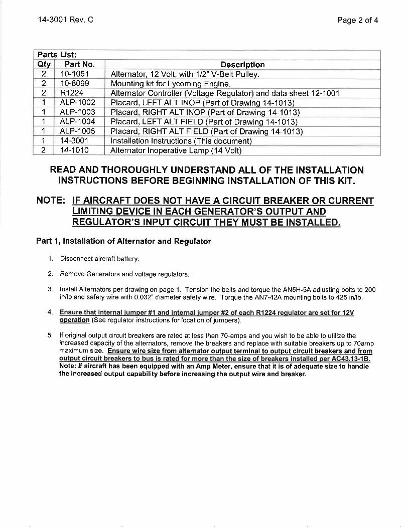
2 10-1051 Alternator, 12 Volt, with 112" V-Belt Pulley.2 10-8099 Mountinq kit for Lvcominq Enqine.2 R1224 Alternator Controller (Voltaqe Requlator) and data sheet 12-10011 ALP-1002 Placard, LEFT ALT INOP (Part of Drawinq 14-1013)1 ALP-1003 Placard, RIGHT ALT INOP (Part of Drawinq 14-1013)1 ALP-1004 Placard, LEFT ALT FIELD (Part of Drawins 14-1013\1 ALP-1005 Placard, RIGHT ALT FIELD (Part of Drawinq 14-1013\1 14-3001 lnstallation lnstructions (This document)2 14-1010 Alternator lnoperative Lamo (14 Volt)
14-3001 Rev. C Page 2 of 4
READ AND THOROUGHLY UNDERSTAND ALL OF THE INSTALLATIONINSTRUCTIONS BEFORE BEGINNING INSTALLATION OF THIS KIT.
NOTE: IF AIRGRAFT DOES NOT HAVE A CIRCUIT BREAKER OR CURRENTLIMITING DEVICE IN EACH GENERATOR'S OUTPUT ANDREGULATOR'S INPUT CIRCUIT THEY MUST BE INST
Part 1, lnstallation of Alternator and Regulator
1. Disconnect aircraft battery.
2. Remove Generators and voltage regulators.
3. lnstall Alternators per drawing on page 1. Tension the belts and torque the AN5H-54 adjusting bolts to 200in/lb and safety wire with 0.032' diameter safety wire. Torque the AN7-424 mounting bolts to 425 inllb.
4.operation (See regulator instructions for location of jumpers).
5. lf original output circuit breakers are rated at less than 70-amps and you wish to be able to utilize theincreased capacity of the alternators, remove the breakers and replace with suitable breakers up to 70ampmaximum size. Ensure wire size from alternator output terminal to output circuit breakers and from
Note: lf aircraft has been equipped with an Amp Meter, ensure that it is of adequate size to handlethe increased output capability before increasing the output wire and breaker.

14-3001 Rev. C Page 3 of 4
6. Wire the system as follows:
f.
For regulator wiring instructions view the regulator installation instructions
Connect the GRND terminal of each regulator to the common aircraft ground.
Leave the ground jumper installed on the F2 terminal of the alternator.
Connect the existing generator output wires to each alternator's 6mm OUTPUT TERMINAL (orinstall a new wire in accordance with AC43.13-1 B) using a MS25171-25 terminal nipple forinsulation (Not Supplied). Torque to 50 in/lb.
Use the original generator field wire or install a new wire, minimum 18AWG, from each alternatorF'l terminal to the FLD terminal of the corresponding regulator. Torque the alternator's F1 terminalnut to 20 in/lb.
lnstall, in view of the pilot, placard ALP-1004 (LEFT ALT FIELD) adjacent to the field switch for theleft alternator and placard ALP-1005 (RIGHT ALT FIELD) adjacent to the switch for the rightalternator.
Ensure that each of the FIELD breakers are connected to the aircraft positive bus.
lf the aircraft has "Generator lnoperative" indicator lamps, they may be used in this step. lf lampsare not currently installed or are not compatible use the supplied lamps Pln 14-1010 Alternatorlnoperative Lamp ('14 Volt) and install them in pilots clear field of view.
lnstall, in view of the pilot, placard ALP-1002 (LEFT ALT INOP) adjacent to the lamp for the leftalternator and placard ALP-1003 (RIGHT ALT INOP) adjacent to the lamp for the right alternator.Also run a new wire, minimum '18AWG, from the AUX terminal of each alternator to the AUXterminal of the corresponding regulator.
7. Adjust and Test the system:
Set both FIELD switches to OFF.Turn on MASTER switch and start the engines. Ensure that both ALT INOP indicators areilluminated.Turn on the LEFT FIELD switch. Check proper charging indication. Check left ALT INOP indicatoris off. Check aircraft maintenance manualfor proper bus voltage (typically 14.0V f 0.3V). Adjustthe left (Master) regulator to the desired bus voltage at 1200 engine RPM.Turn off the LEFT FIELD switch and turn on the RIGHT FIELD switch. Check proper chargingindication. Check right ALT INOP indicator is off. At 1200 engine RPM Adjust the right (Slave)regulator to the same bus voltage as left alternator.Turn on the LEFT FIELD switch.Check proper charging indication. Check bus voltage.Recheck and inspect the entire installation. Complete FAA form 337, make log book entry, updateaircraft equipment list, and weight and balance.
Alþfnator anO lt¡ountinq
10-8099 MOUNTING KIT COMPONENTSQTY P/N DESCRIPTION OTY P/N DESCRIPTION
1 AN5H.5A BOLT 1 10-1012 TENSION ARMI 4N960-516 WASHER 1 1 0-1 009 SPACER BUSHING1 AN7-42A BOLT 1 10-1002 STARTER STRAP1 4N960-716 WASHER 1 10-8003 CASE MOUNT BRACKET1 4N363-720 NUT 1 10-'1003 BOSS MOUNT BRACKET
c.
d.
e
a.
b.
g.
h.
c.
d.
e.
f.g.
ab

14-3001 Rev. C Page 4of 4
Parl2, Preparation of FAA Form 337
1. lnstalled Alternators in accordance with Supplemental Type Certificate No. SAl0682SC. Updated AirplaneFlight Manual with HET Airplane Flight Manual Supplement 002 (or later revision). Weight changed(compute weight and balance as necessary). Checked size of wire from Alternator output terminals toalternator circuit breakers and from Alternator circuit breakers to bus and size of Alternator circuit breakerswith AC43.13-18. (Note: use this statement as applicable. lf wire and circuit breaker sizes are satisfactory,so state. lf not satisfactory, state wire and/or circuit breaker size installed to conform with 4C43.13-1 B.)
2. Modified aircraft equipment list by removal of generators listed and adding Model TAL12-70 Alternator Kit.
Weight and Balance
Removed two generator installations:
WeightArm(Refer to Aircraft Equipment List)
Removed two regulator installations:
WeightArm(Refer to Aircraft Equipment List)
lnstalled TAL12-7O alternator kitconsisting of:
wgt.(2) 10-1051 alternators 20.01bs.(2) 10-8099 mounting kits. 2.0 lbs.(2) R1224Voltage Regulators 0.6 lbs.(1 ) ALP-1002 Placard Neqliqible(1 ) ALP-1003 Placard Neqliqible(1) ALP-1004 Placard Neqlisible(1) ALP-1005 Placard Neqliqible(2) 14-1010 Lamps Neoliqible
Part 3, Instructions for Continued Airworthiness
PERIODIC MAINTENANCE:1. lt is recommended that the operation of the TAL12-70 alternator be checked every 100 hour inspection
or every annual inspection which ever comes first.
2. ANNUAL/1OO HOUR INSPECTION:
a. Remove drive belt and turn alternator rotor to check condition of bearings for abnormal noise orroughness.
b. Each annual/100 hour inspection, the alternator and its associated wiring should be checkedfor secure electrical connections and physical connection to the airframe. The belt drivetension should be re-set to the aircraft manufacturer's specification.
3. 5 YEAR OR lOOO HOUR INSPECTIONa. Repeat the Annual/100 hour inspection.b. Remove field brush assembly and inspect brushes for excess wear. Replace brush assembly
if brushes extend less then 0.250 inches from edge of holder case.
AI RWORTH INESS LIM ITATIONS
There are no mandatory replacement limits. There are no mandatory structural inspection intervals.
THE AIRWORTHINESS LIMITATIONS SECTION IS FAA APPROVED AND SPECIFIES MAINTENANCEREQUIRED UNDER SEC. 43.16 AND 91.403 OF THE FEDERAL AVIATION REGULATIONS UNLESS ANALTERNATIVE PROGRAM HAS BEEN FAA APPROVED.

r0-t0t2
AN9ó0-51ó
AN5H-5A
OF FAA PMA NAMEPLATE
F2 TERMINAL(GROUND)
FI TERMINAL
AN363-720 AUX TERMINALóMM OUTPUTTERMINAL
AN9ó0-Zró sMM STUD (3)
AN7-424
r0-r03r
I 0-8003(CASE MOUNT BRACKET)
]O-]OO3 AS REQUIRED(BOSS MOUNT BRACKET)
NOTES:
l. NOTE: FOR STANDARD 7.5" DIAMETERusE PTPER V-BELT p/N 452-541 (GATES
RING GEAR SUPPORT PULLEY
9335X1). NOT SUPPLTED.
FWerFAA PMAHARTZELL ENGINE
10-5051EEIIEUET E2.YWWSNNEITilGil z¿
FIRST RELEASE INTO HET DESIGN DATA 9 l\ol1 4
PAGE 3 TO PAGE I. 2) ADDED HET TITLEBLOCK 3)HARTZELL ENGINE TECHNOLOGIES WAS PLANE
POWER, LTD. 4) ADDED t0-r03.l CALLOUTTO DATATAG. 5) MODEL NO. r0-505r WAS TAL24-70.
ó)REMOVED "PLANE POWER LDT." AND/OR REPLACEDWITH ''HET'WHERE APPLICABLE. 7) '.PER DRAWING ON
9 /tolt 4
2900 Selmo HÌghwoyMonlgomery, At 3ó108
UNLESS OTHERWISE SPECIFIEDGEOMETRIC SYMBOLS
PER ANSIYI4.5DIMENSIONS ARE IN INCHES AND APPLYAFIER HEAT TREAT AND PLATING
.X = !.015
.XX = 1.010 ANGLES 1ì '
.XXX = 1.005BREAK ALL EDGES AND MACHINE ALLINSIDE CORNER FILLETS .OI5 MAX.
tzs/SURFACE rl¡.tlSH V
z Fh.TNESS
S] RA IGHT N ESS
O RouNDNÊss
Þ cYuNDRcrY
ô PRoF|LE
I PERPENDTcuLARnY
+ PosroN
O coNcENTRrc[Y
= SYMMETRY
Z ANGUIARÍTY
// PARALLEuSM
,/ crRcur.AR RuNouT
SPECIFICATION CLASSIFICATION
T AI24-70 INSTALLATIONINSTRUCTIONS
THIS DRAWING CONTAINS INIORMATION THAT 15
CONF¡DENTIAL AND PROPRIETARY IO HAR-TZELL
ENGINE TECHNOLOGIES'TH15 DRAWING IS TURNISHEDON IHE UNDERSÌANDING THAT THE DRAWING AND
THE INFORMATION IT CONIAINS WILL NOI BE COPIEDOR DISCIOSED TO OIHERS EXCEPT WITH THE WRITTEN
CONSENT OT HARTZELL ENGINE TECHNOLOGIES, WILT
NOT BE USED TO THE DEIRIMENT OF HARTZELL ENGINETECHNOLOGIES, AND WILL BE REIURNED UPONREOUEST BY HAR'IZELL ENGINE
-IECHNOLOGIES
MATERIALSEE INDIVIDUAL PARTS
DRAWING NO.
14-4001CODE ID
ósPYISCALE NTS

Parts List:Qtv Part No. Descriotion
2 10-5051 Alternator,24Volt, with 1 12" V-Belt Pulley.2 1 0-8099 Mountino kit for Lvcominq Enqine.2 R1224 Alternator Controller (Voltaqe Requlator) and data sheet 12-10011 ALP-1002 Placard, LEFT ALT INOP (Part of Drawing 14-1013)1 ALP-1003 Placard, RIGHT ALT INOP (Part of Drawinq 14-1013)1 ALP-r004 Placard, LEFT ALT FIELD (Part of Drawins 14-1013)1 ALP-1005 Placard, RIGHT ALT FIELD (Part of Drawinq 14-1013)1 14-4001 lnstallation lnstructions (This document)2 14-1011 Alternator lnoperative Lamp (28 Volt)
14-4001 Rev. C Page 2of 4
READ AND THOROUGHLY UNDERSTAND ALL OF THE INSTALLATIONINSTRUCTIONS BEFORE BEGINNING INSTALLATION OF TH¡S KIT.
NOTE: IF AIRCRAFT DOES NOT HAVE A CIRCUIT BREAKER OR GURRENTLIMITING DEVICE IN EACH GENERATOR'S OUTPUT ANDREGULATOR'S INPUT CIRCUIT THEY MUST BE INSTALLED.
Part 1, lnstallation of Alternator and Regulator
1. Disconnect aircraft battery.
2. Remove Generators and voltage regulators.
3. lnstall Alternators per drawing on page 1. Tension the belts and torque the AN5H-54 adjusting bolts to 200in/lb and safety wire with 0.032' diameter safety wire. Torque the AN7-424 mounting bolts to 425 inllb.
4.operation (See regulator instructions for location of jumpers).
5. lf original output circuit breakers are rated at less than 70-amps and you wish to be able to utilize theincreased capacity of the alternators, remove the breakers and replace with suitable breakers up to 70ampmaximum size. Ensure wire size from alternat
Note: lf aircraft has been equipped with an Amp Meter, ensure that it is of adequate size to handlethe increased output capability before increasing the output wire and breaker.

14-4001 Rev. C Page 3 of 4
6. Wire the system as follows:
a. For regulator wiring instructions view the regulator installation instructions.
b. Connect the GRND terminal of each regulator to the common aircraft ground.
c. Leave the ground jumper installed on the F2 terminal of the alternator.
d. Connect the existing generator output wires to each alternator's 6mm OUTPUT TERMINAL (orinstall a new wire in accordance with 4C43.13-1 B) using a MS251 71-25 terminal nipple forinsulation (Not Supplied). Torque to 50 in/lb.
e. Use the original generator field wire or install a new wire, minimum 18AWG, from each alternatorF1 terminal to the FLD terminal of the corresponding regulator. Torque the alternator's F'1 terminalnut to 20 in/lb.
f. lnstall, in view of the pilot, placard ALP-1004 (LEFT ALT FIELD) adjacent to the field switch for theleft alternator and placard ALP-1005 (RIGHT ALT FIELD) adjacent to the switch for the rightalternator.
g. Ensure that each of the FIELD breakers are connected to the aircraft positive bus.
h. lf the aircraft has "Generator lnoperative" indicator lamps, they may be used in this step. lf lampsare not currently installed or are not compatible use the supplied lamps Pln 14-101'1 Alternatorlnoperative Lamp (28 Volt) and install them in pilots clear field of view.
i. lnstall, in view of the pilot, placard ALP-1002 (LEFT ALT INOP) adjacent to the lamp for the leftalternator and placard ALP-1003 (RIGHT ALT INOP)adjacent to the lamp for the right alternator.Also run a new wire, minimum 18AWG, from the AUX terminal of each alternator to the AUXterminal of the corresponding regulator.
7. Adjust and Test the system:
a. Set both FIELD switches to OFF.b. Turn on MASTER switch and start the engines. Ensure that both ALT INOP indicators are
illuminated.c. Turn on the LEFT FIELD switch. Check proper charging indication. Check left ALT INOP indicator
is off. Check aircraft maintenance manualfor proper bus voltage (typically 28.0V t 0.3V). Adjustthe left (Master) regulator to the desired bus voltage at 1200 engine RPM.
d. Turn off the LEFT FIELD switch and turn on the RIGHT FIELD switch. Check proper chargingindication. Check right ALT INOP indicator is off. At 1200 engine RPM Adjust the right (Slave)regulator to the same bus voltage as left alternator.
e. Turn on the LEFT FIELD switch.f. Check proper charging indication. Check bus voltage.g. Recheck and inspect the entire installation. Complete FAA form 337, make log book entry, update
aircraft equipment list, and weight and balance.
Mountinq Kit Pafts List
10-8099 MOUNTING KIT COMPONENTSQTY P/N DESCRIPTION QTY P/N DESCRIPTION
1 ANSH-54 BOLT 1 10-1012 TENSION ARM1 4N960-516 WASHER 1 1 0-1 009 SPACER BUSHING1 AN7-424 BOLT 1 1 0-1 002 STARTER STRAP1 4N960-716 r¡úASHER 1 10-8003 CASE MOUNT BRACKET1 4N363-720 NUT 1 10-'1003 BOSS MOUNT BRACKET

14-4001 Rev. C
Parl2, Preparation of FAA Form 337
Page 4 of 4
1. lnstalled Alternators in accordance with Supplemental Type Certificate No. SA10682SC. Updated AirplaneFlight Manual with HET Airplane Flight Manual Supplement 002 (or later revision). Weight changed(compute weight and balance as necessary). Checked size of wire from Alternator output terminals toalternator circuit breakers and from Alternator circuit breakers to bus and size of Alternator circuit breakerswith 4C43.13-'18. (Note: use this statement as applicable. lf wire and circuit breaker sizes are satisfactory,so state. lf not satisfactory, state wire and/or circuit breaker size installed to conform with AC43.13-18.)
2. Modified aircraft equipment list by removal of generators listed and adding Model f AL24-70 Alternator Kit.
Weight and Balance
Removed two generator installations:
WeightArm(Refer to Aircraft Equipment List)
Removed two regulator installations:
WeightArm(Refer to Aircraft Equipment List)
lnstalled TAL 24-70 alternator kitconsisting of:
(2) 10-5051 alternators(2) 10-8099 mounting kits.(2) R1 224 V oltage Regulators(1) ALP-1002 Placard(1 ) ALP-1003 Placard(1) ALP-1004 Placard(1 ) ALP-1005 Placard(2) 14-1011 Lamps
wgt.20.01bs.2.0 lbs.0.6 lbs.NeqliqibleNeqlisibleNeqliqibleNeqlisibleNeqliqible
Part 3, lnstructions for Continued Airworthiness
PERIODIC MAINTENANCE:1. lt is recommended that the operation of the TAL24-70 alternator be checked every 100 hour inspection
or every annual inspection which ever comes first.
2. ANNUAL/1OO HOUR INSPECTION:
a. Remove drive belt and turn alternator rotor to check condition of bearings for abnormal noise orroughness.
b. Each annual/100 hour inspection, the alternator and its associated wiring should be checkedfor secure electrical connections and physical connection to the airframe. The belt drivetension should be re-set to the aircraft manufacturer's specification.
3. 5 YEAR OR lOOO HOUR INSPECTIONa. Repeat the Annual/100 hour inspection.b. Remove field brush assembly and inspect brushes for excess wear. Replace brush assembly
if brushes extend less then 0.250 inches from edge of holder case.
AI RWORTHINESS LI M ITATIONS
There are no mandatory replacement limits. There are no mandatory structural inspection intervals.
THE AIRWORTHINESS LIMITATIONS SECTION IS FAA APPROVED AND SPECIFIES MAINTENANCEREQUIRED UNDER SEC. 43.16 AND 91.403 OF THE FEDERAL AVIATION REGULATIONS UNLESS ANALTERNATIVE PROGRAM HAS BEEN FAA APPROVED.

ì0-ì012
AN9ó0-5tó
AN5H-5A
FAA PMA NAMEPLATE
F2 TERMINAL(GROUND)
FI TERMINAL
AN3ó3-720 AUX TERMINALóMM OUTPUTTERMINAL
AN9ó0-71ó sMM STUD (s)
AN7-42A
r 0-8003(cASE MOUNT BRACKET)
IO-IOO3 AS REQUIRED
lBoss MoUNT BRACKET)
NOTES:
I. FOR STANDARD 7.5 DIAMETER RING GEAR SUPPORT PULLEYusE PtpER V-BELT plN 452-541 (GATES 9335X1). NOT SUppLtED
FWerFAA PMAHÀRTZELL ENGINE
10-1051EEIIEITET B2-YVVWSNNEIIilGEI Tz
FIRST RELEASE INTO HET DESIGN DATA 9110/14
PAGE 3 TO PAGE r . 2) ADDED HET TTTLEBLOCK 3)HARTZELL ENGINE TECHNOLOGIES WAS PLANE
powER, LfD. 4) ADDED t0-t031 CALLOUTTO DAïATAG. 5) MODEL NO. l0-.l05ì WAS SALI2-/0.
ó)REMOVED ''PLANE POWER LDT." AND/OR REPLACEDWITH ''HE]"'WHERE APPLICABLE. 7) ''PER DRAWING ON
9110114
GEOMETRIC SYMBOLSPER ANSIYI4.5
UNLESS OTHERWISE SPECIFIED
DIMENSIONS ARE IN INCHES AND APPLYAFIER HEAT TREAT AND PLATING
.X = t.015
.XX = i.010 ANGLES 1l'
.XXX = 1 005BREAK ALL EDGES AND MACHINE ALLINSIDE CORNER FILLETS .Oì5 MAX.
12s/suRFAcE nNtsH V
CHECKED
ã FLATNESS
STRAIGHINESS
Q nounoress
H cYuNDRcrrY
ô PRoFTLÊ
A PERPENDTcuLARTTY
+ PosrroN
O coNcEMRrc[Y
= SYMMEfRY
-Z ANcULARffY
// PARALLELTsM
,/ crRcuLAR RUNou
S P ECIFICATIO N CLASSIFICATION
SAL I 2-70 INSTALLATIONINSTRUCTIONS
MATERIALSEE INDIVIDUAL PARTS
THIS DRAWING CONTAINS INFORMAIION-THAI IS
CONFIDENTIAL AND PROPRIEIARY TO HARTZELL
ENGINETECHNOLOGIES THIS DRAWING IS FURNISHED
ON'IHE UNDERSIANDING THAI THE DRAWING ANDTHE INFORMATION IT CONTAINS WILL NOT BE COPIEDOR DISCLOSED TO OTHERS EXCEPT WfTH THE WRTTTEN
CONSENT OT HARTZELL ENGINETECHNOLOGIES, WILL
NOT BE USED IO THE DEIRIMENI OF HARÍZELL ENGINETECHNOLOGIES, AND WILL BE RETURNED UPONREQUEST BY HARTZETL ENGINE'TECHNOLOGIES.
fxx xxlDRAWING NO.
r 4-5001(XX XX)

Parts List:Qtv Part No. Description
1 1 0-1 051 Alternator, 12 Volt, with 1/2" V-Belt Pulley.1 10-8099 Mountino kit for Lvcomino Enoine.1 R1224 Alternator Controller (Voltaoe Reoulator) and data sheet 12-10011 ALP-1001 Placard, ALT FIELD (Part of Drawing 14-1012)1 ALP-1006 Placard, ALT INOP (Part of Drawing 14-1012\1 14-5001 lnstallation lnstructions ffhis document)1 14-1010 Alternator Inoperative Lamp (14 Volt)
Dwg. 14-5001 Rev. C
READ AND THOROUGHLYINSTRUCTIONS BEFORE
Page 2of 4
UNDERSTAND ALL OF THE INSTALLATIONBEGINNING INSTALLATION OF THIS KIT.
NOTE: lF AIRCRAFT IT BREAKER OLIMITING DEVICE IN THE GENERATOR'S OUTPUT ANDREGULATOR'S INPUT CIRCUIT THEY MUST BE INSTALLED.
Part l, lnstallation of Alternator and Regulator
1. Disconnect aircraft battery.
2. Remove Generator and voltage regulator.
3. lnstall Alternator per drawing on page 1. Tension the belt and torque the ANSH-5A adjusting bolts to 200in/lb and safety wire with 0.032" diameter safety wire. Torque the AN7-424 mounting bolts to 425 inllb.
4.operation (See regulator instructions for location of jumpers).
5. lf original output circuit breaker is rated at less than 70-amps and you wish to be able to utilize theincreased capacity of the alternator, remove the breaker and replace with suitable breaker up to 70ampmaximum size. Ensure wire size from alternator output terminal to output circuit breaker and from
Note: lf aircraft has been equipped with an Amp Meter, ensure that it is of adequate size to handlethe increased output capability before increasing the output wire and breaker.

Dwg. 14-5001 Rev. C Page 3 of 4
6. Wire the system as follows:
a. For regulator wiring instructions view the regulator installation instructions.
b. Connect the GRND terminal of the regulator to the common aircraft ground.
c. Leave the ground jumper installed on the F2 terminal of the alternator.
d. Connect the existing generator output wire to the alternator's 6mm OUTPUT TERMINAL (or installa new wire in accordance with AC43.13-1 B) using a MS25171-25 terminal nipple for insulation (NotSupplied). Torque to 50 in/lb.
e. Use the original generator field wire or install a new wire, minimum 18AWG, from the alternator F1terminal to the FLD terminal of the regulator. Torque the alternator's F1 terminal nut to 20 in/lb.
f. lnstall, in view of the pilot, placard ALP-1001 (ALT FIELD) adjacent to the field switch for thealternator.
g. Ensure that the FIELD switch/breaker is connected to the aircraft positive bus.
h. lf the aircraft has a "Generator lnoperative" indicator lamp, it may be used in this step. lf the lamp isnot currently installed or is not compatible use the supplied lamp P/n 14-1010 Alternatorlnoperative Lamp (14 Volt) and install it in pilots clear field of view.
i. lnstall, in view of the pilot, placard ALP-1006 (ALT INOP) adjacent to the indicator for thealternator. Also run a new wire, minimum 18AWG, from the AUX terminal of the alternator to theAUX terminal of the regulator.
7. Adjust and Test the system:
a. Set FIELD switch to OFF.
b. Turn on MASTER switch and start the engine. With FIELD switch in OFF position ensure that ALTINOP indicator is illuminated.
c. Turn on the FIELD switch. Check proper charging indication. Check ALT INOP indicator is off.Check aircraft maintenance manualfor proper bus voltage (typically 14.0V t 0.3V). Adjust theregulator to the desired bus voltage at 1200 engine RPM.
d. Recheck and inspect the entire installation. Complete FAA form 337, make log book entry, updateaircraft equipment list, and weight and balance.
Mountinq Kit Parts List
10-8099 MOUNTING KIT COMPONENTSQTY P/N DESCRIPTION QTY P/N DESCRIPTION
1 AN5H-5A BOLT 1 10-1012 TENSION ARM1 4N960-516 WASHER 1 1 0-r 009 SPACER BUSHING1 AN7-42A BOLT 1 10-1002 STARTER STRAP1 4N960-716 /VASHER 1 I 0-8003 CASE MOUNT BRACKET1 4N363-720 NUT 1 1 0-1 003 BOSS MOUNT BRACKET

Dwg. 14-5001 Rev. C Page 4 of 4
Parl2, Preparation of FAA Form 337
1 . lnstalled Alternator in accordance with Supplemental Type Certificate No. S410682SC. Updated AirplaneFlight Manual with HET Airplane Flight Manual Supplement 001 (or later revision). Weight changed(compute weight and balance as necessary). Checked size of wire from Alternator output terminal toalternator circuit breaker and from Alternator circuit breaker to bus and size of Alternator circuit breakerwith 4C43.13-18. (Note: use this statement as applicable. lf wire and circuit breaker sizes are satisfactory,so state. lf not satisfactory, state wire and/or circuit breaker size installed to conform with 4C43.13-18.)
2. Modified aircraft equipment list by removal of generator listed and adding Model SAL12-70 Alternator Kit.
Weight and Balance
Removed generator installation :
WeightArm(Refer to Aircraft Equipment List)
Removed regulator installation :
WeightArm(Refer to Aircraft Equipment List)
lnstalled SAL 12-70 alternator kitconsisting of:
(1
(1
(1
(1
(1
(1
10-1051 alternator10-8099 mounting kits.R1 224 Voltage RegulatorALP-1001 PlacardALP-1006 Placard14-1010 Lamp
Part 3, lnstructions for Gontinued Ainryorthiness
PERIODIC MAINTENANCE:1. lt is recommended that the operation of the SALI 2 -70 allernator be checked every 100 hour inspection
or every annual inspection which ever comes first.
2. ANNUAL/1OO HOUR INSPECTION:
a. Remove drive belt and turn alternator rotor to check condition of bearings for abnormal noise orroughness.
b. Each annual/100 hour inspection, the alternator and its associated wiring should be checkedfor secure electrical connections and physical connection to the airframe. The belt drivetension should be re-set to the aircraft manufacturer's specification.
3. 5 YEAR OR lOOO HOUR INSPECTIONa. Repeat the Annual/100 hour inspection.b. Remove field brush assembly and inspect brushes for excess wear. Replace brush assembly
if brushes extend less then 0.250 inches from edge of holder case.
AIRWORTHINESS LI MITATIONS
There are no mandatory replacement limits. There are no mandatory structural inspection intervals.
THE AIRWORTHINESS LIMITATIONS SECTION IS FAA APPROVED AND SPECIFIESMAINTENANCE REQUIRED UNDER SEC. 43.16 AND 91.403 OF THE FEDERAL AVIATIONREGULATIONS UNLESS AN ALTERNATIVE PROGRAM HAS BEEN FAA APPROVED.

r0-30r2
AN9ó0-5ìó
I 0-900ó F2 TERMINAL(GRouND)ì 0-9004 9ó0-5 ì ó
MS35338- 5
MS20074-05-r2
FI TERMINAL(INTERAV REGULATORF TERMINAL)
r 0-3009 ANó-4IA AUX TERMINAL(NOT USED)
óMM OUTPUTTERMINAL
BATTERY WIRE
INTERNAL REG+WIRE
AN9ó0-ó1ó 3X sMM STUD
r0-3010INSTALL USINGTHIS HOLE LOCATION OF
FAA PMANAMEPLATE
AN9ó0-8trr----
ô
NOTES:
LTCM# s39547-31 .19 V-BELT REQUTRED (pURCHASE SEPERATELY)
ffig¡ FAA PMAHARTZELL ENCfNE
10-1050cEEIUEE A2.YVVWSNIlõrIilGril 12
FIRST RELEASE INTO HET DESIGN DATA I /toll 4
PAGE 3 TO PAGE ì . 2) ADDED HET TIILEBLOCK 3)HARÏZELL ENGINE TECHNOLOGIES WAS PLANE
POWER, LTD. 4) ADDED l0-t03t CALLOUTTO DATATAG. 5) MODEL NO. 10-ì050C WAS SALt 2-70C.
ó)REMOVED "PLANE POWER LDT." AND/OR REPLACEDwtTH "HEI'WHERE APPLTCABLE. /) "PER DRAWING ON
I /to/t 4
GEOMETRIC SYMBOLSPER ANSIYI4.5
UNLESS OTHERWISE SPECIFIED
ARE IN INCHES AND APPLYAFTER HEAT TREAT AND PLAIING
.X = 1.015
.XX = t.010 ANGLES tl'
.XXX = t.005BREAK ALL EDGES AND MACHINE ALLINSIDE CORNER FILLETS.O]5 MAX.
12s/sURFACE ¡r¡r¡sH V
STRA6HTNESS
O RouNDNEss
ø cYLTNDRcnY
ô enorlre
I PERPENDTcuhRnY
+ PosnoN
O coNcEMRrc[Y
= SYMMETRY
Z ANGUURÍIY
// PARATTEuSM
,/ crRcuLAR RUNour
SP ECIFICATION CLASSI FICATION
SAL I 2-7 OC I NSTALLATIONINSTRUCTIONS
MATERIALSEE INDIVIDUAL PARTS
THIS DRAWING CONIAINS INfORMATION THAI 15
CONFIDENTIAL AND PROPRIETARY IO HARTZELL
ENGINE TECHNOLOGIES THIS DRAWING IS FURNISHEDON THE UNDERS'IANDING THAT THE DRAWING AND
IHE INFORMAÌION IT CONIAINS WILL NOT BE COPIEDOR DISCLOSED TO OTHERS EXCEPT WITH'IHE WRIITENCONSENT OF HARTZELL ENGINE TECHNOLOGIES, WILLNOI BE USED TO IHE DETRIMENI OF HAR'IZELL ENGINE
IECHNOLOGIES, AND WILL BE REIURNED UPONREQUEST BY HARTZETL ENGINE TECHNOTOGIES
[XX XX]DRAWING NO,
I 4-ó001CODE ID
ósPY1SCALE NTS

Parts List:Qtv Part No. Description
1 1 0-1 050c Alternator, 12 Volt, with 3.0" Diameter 3/8" V-Belt Pulley.1 10-9099 Mountinq kit for Continental Enqine.1 R1224 Alternator Controller (Voltaqe Requlator) and data sheet 12-10011 ALP-1001 Placard, ALT FIELD (Part of Drawinq 14-1012\1 ALP-1006 Placard, ALT INOP (Part of Drawinq 14-1012)1 14-6001 lnstallation lnstructions (This document)1 14-1010 Alternator lnoperative Lamp (14 Volt)
14-6001 Rev. D Page 2 of 4
READ AND THOROUGHLY UNDERSTAND ALL OF THE INSTALLATIONINSTRUCTIONS BEFORE BEGINNING INSTALLATION OF THIS KIT.
NOTE: IF AIRCRAFT DOES NOT HAVE A CIRCUIT BREAKER OR CURRENTLIMITING DEVICE IN THE GENERATOR'S OUTPUT ANDREGULATOR'S INPUT CIRCUIT THEY MUST BE INSTALLED.
Part l, lnstallation of Alternator and Regulator
1. Disconnect aircraft battery.
2. Remove Generator and voltage regulator.
3. lnstall Alternator per drawing on page 1 . Tension the belt and torque the ANSH-74 adjusting bolts to 100 -140 in/lb and safety wire with 0.032' diameter safety wire. Torque the AN6-414 mounting bolts to 160 -190 in/lb.
4.operation (See regulator instructions for location of jumpers).
5. lf original output circuit breaker is rated at less than 70-amps and you wish to be able to utilize theincreased capacity of the alternator, remove the breaker and replace with suitable breaker up to 70ampmaximum size. Ensure wire size from alternator output terminal to output circuit breaker and from
Note: lf aircraft has been equipped with an Amp Meter, ensure that it is of adequate size to handlethe increased output capability before increasing the output wire and breaker.

14-6001 Rev. D Page 3 of 4
6. Wire the system as follows:
a. For regulator wiring instructions view the regulator installation instructions.
b. Connect the GRND terminal of the regulator to the common aircraft ground.
c. Leave the ground jumper installed on the F2 terminal of the alternator.
d. Connect the existing generator output wire to the alternator's 6mm OUTPUT TERMINAL (or install. a new wire in accordance with 4C43.13-18) using a MS25171-25 terminal nipple for insulation (Not
Supplied). Torque to 50 in/lb.
e. Use the original generator field wire or install a new wire, minimum 18AWG, from the alternator F1terminal to the FLD terminal of the regulator. Torque the alternator's F1 terminal nut to 20 inllb.
f. lnstall, in view of the pilot, placard ALP-1001 (ALT FIELD) adjacent to the field switch for thealternator.
g. Ensure that the other end of the FIELD switch/breaker is connected to the aircraft positive bus.
h. lf the aircraft has a "Generator lnoperative" indicator lamp, it may be used in this step. lf the lamp isnot currently installed or is not compatible use the supplied lamp P/n 14-1010 Alternatorlnoperative Lamp (14 Volt) and install it in pilots clear field of view.
i. lnstall, in view of the pilot, placard ALP-1006 (ALT INOP) adjacent to the indicator for thealternator. Also run a new wire, minimum 18AWG, from the AUX terminal of the alternator to theAUX terminal of the regulator.
7. Adjust and Test the system:
a. Set FIELD switch to OFF.
b. Turn on MASTER switch and start the engine. With FIELD switch in OFF position ensure that ALTINOP indicator is illuminated.
c. Turn on the FIELD switch. Check proper charging indication. Check ALT INOP indicator is off.Check aircraft maintenance manual for proper bus voltage (typically 14.0V t 0.3V). Adjust theregulator to the desired bus voltage al12OO engine RPM.
d. Recheck and inspect the entire installation. Complete FAA form 337, make log book entry, updateaircraft equipment list, and weight and balance
Mountinq Kit Parts List1U-9U99 MOUN I ING KI I CJOMPONEN I S
QTY P/N UESL;I-{IP I ION QIY P/N DESCRIP I IONì U.3UUV SPAL;EI-{ BUSHING 4N960-E1ttL WASHER1U-3U1U SPACER 2 4N960-6'l 6 WASHERI U-i't.t I Z SPAL;tt-( 2 4N960-51 6 WASHERI t.,-v(rtr.1 UON I INEN tAL BRACKET 1 MIs20074-05-1 2 BOLTItr-vtrU¿t IENSION ARM f\NbH-/A BOLT
-vUt trr SUPPORT BRACKET qNb-414 BOLTrvrs3533E-45 -OCK WASHER ,l vt5z1u45-b NU

14-6001 Rev. D Page 4of 4
Part 2, Preparation of FAA Form 337
1. lnstalled Alternator in accordance with Supplemental Type Certificate No. SA10682SC. Updated AirplaneFlight Manual with HET Airplane Flight Manual Supplement 001 (or later revision). Weight changed(compute weight and balance as necessary). Checked size of wire from Alternator output terminal toalternator circuit breaker and from Alternator circuit breaker to bus and size of Alternator circuit breakerwith 4C43.13-l B. (Note: use this statement as applicable. lf wire and circuit breaker sizes are satisfactory,so state. lf not satisfactory, state wire and/or circuit breaker size installed to conform with 4C43.13-18.)
2. Modified aircraft equipment list by removal of generator listed and adding Model SALI2-70C Alternator Kit.
Weight and Balance
Removed generator installation :
WeightArm(Refer to nircraft equipment List)
Removed regulator installation :
WeightArm(Refer to Aircraft Equipment List)
f nstalled SAL 12-70C alternatorconsisting of:
(1 ) 1 0-1 050C alternator(1) 10-9099 mounting kit.(1 ) R1 224 Voltage Regulator(1) ALP-1001 Placard(1 ) ALP-1006 Placard(1) 14-1010 Lamp
kit
wgt.10.01bs.1.4 lbs.0.3 lbs.NeqliqibleNeqliqibleNeqliqible
Part 3, lnstructions for Continued Ainvorthiness
PERIODIC MAINTENANCE:1 . lt is recommended that the operation of the SALI2-70C alternator be checked every 100 hour
inspection or every annual inspection which ever comes first.
2. ANNUAL/1OO HOUR INSPECTION:
a. Remove drive belt and turn alternator rotor to check condition of bearings for abnormal noise orroughness.
b. Each annual/100 hour inspection, the alternator and its associated wiring should be checkedfor secure electrical connections and physical connection to the airframe. The belt drivetension should be re-set to the aircraft manufacturer's specification.
3. 5 YEAR OR ,1OOO HOUR INSPECTIONa. Repeat the Annual/100 hour inspection.b. Remove field brush assembly and inspect brushes for excess wear. Replace brush assembly
if brushes extend less then 0.250 inches from edge of holder case.
AIRWORTHINESS LIMITATIONS
There are no mandatory replacement limits. There are no mandatory structural inspection íntervals.
THE AIRWORTHINESS LIMITATIONS SECTION IS FAA APPROVED AND SPECIFIES MAINTENANCEREQUIRED UNDER SEC. 43.16 AND 91.403 OF THE FEDERAL AVIATION REGULATIONS UNLESS ANALTERNATIVE PROGRAM HAS BEEN FAA APPROVED.