Embed Size (px)
Citation preview
LCDD-PC User
C22r Gui
Seriide
ies
FCC-B
the limitsdesigneinstallatinot instainterferewill not oto radio on, the umeasure
R In C
re C
Notice 1
Notice 2
Tradem
All tradeIntel® isWindowAward®AMI® is
Radio Fr
s for a classd to provideion. This eqalled and usence to radioccur in a por televisiouser is encoes listed be
Reorient or ncrease the
Connect theeceiver is c
Consult the
1 The crespoequip
2 Shieldto com
marks
emarks are s a registere
ws® 7/Vista® is a registe
a registere
requency
s B digital de reasonabquipment gesed in accoio communparticular inon receptionouraged to
elow. relocate the
e distance be equipmenconnected. dealer or a
changes or onsible for cpment.
ded interfacmply with th
the propered tradema
a/XP/NT/200ered trademed tradema
y Interfere
This equipdevice, pursble protectioenerates usordance witications. H
nstallation. In, which ca try to corre
e receivingbetween tht into an ou
an experien
modificatiocompliance
ce cables ahe emissio
rties of theirarks of Intel00/98/95 armark of Phoark of Amer
i
ence State
pment has suant to paon against ses and canth the instruowever, theIf this equipn be determect the inte
antenna. e equipmenutlet on a ci
nced radio/t
ons not expe could void
and A.C. pon limits.
r respectivel Corporatiore registereoenix Techican Megat
ement
been testeart 15 of theharmful intn radiate rauction manuere is no gupment doesmined by turference by
nt and receircuit differe
television te
pressly appd the user's
ower cord, i
e owners. on. ed trademarnologies Lttrends Inc
d and foune FCC ruleserference i
adio frequenual, may cauarantee ths cause harurning the ey one or mo
eiver. ent from tha
echnician fo
proved by ths authority t
f any, must
rks of Microtd.
d to complys. These limn a residenncy energy ause harmfhat interferermful interfeequipment oore of the
at to which
or help.
he party to operate t
t be used in
osoft Corpo
y with mits are ntial and, if
ful ence erence off and
the
the
n order
oration.
Safe 1. Al2. Ke3. La4. Th
eq5. Co
be6. Pl
pl7. Al8. Al9. Ne
sh10. Do
co11. Th
copr
12. Do13. W
mCaANG
14. If se
15. Dom
DO NOTSTORAGEQUIPM CAUTIOsame or
ty Inst
ways read eep this eqay this equihe openingquipment fronfirm the vefore conneace the poace anythinways unplul cautions aever pour ahock. o not disabonnected tohe Optical Sontrols or adrohibited. o not touch
When installietal shield able distribNSI/NF PA rounding ofany of the f
ervice persoThe powLiquid haThe equiThe equithe UserThe equiThe equi
o not attemodification
T LEAVE TGE TEMPE
MENT.
ON: Dangerr equivalent
tructio
the safety uipment awpment on as on the en
rom overhevoltage of tecting the ewer cord inng over theug the Powand warninany liquid in
ble the proteo a groundeStorage dedjustments
h the Laser ng the coaxis reliably cution syste70, the Na
f Outer Confollowing sionnel:
wer cord or pas penetratipment hasipment hasr's Guide. ipment hasipment has
mpt to removshould be c
THIS EQUIPERATURE
r of explosiot type recom
ns
instructionsway from hua reliable flanclosure areating. DO Nthe power sequipment tn such a wae power corwer Cord be
gs on the ento the ope
ective groued main socvices are c
s or perform
lens insidexial cable toconnected tms should
ational Electnductive Shituations ar
plug is damted into the s been expos not worked
s been drops obvious sive or upgraconducted
PMENT IN ABOVE 50
on if batterymmended b
ii
s carefully.umidity. at surface be for air conNOT COVEsource and to the poweay that it card. fore inserti
equipment sning. This
nding pin frcket/outlet.
classified asmance of pro
e the opticao the TV Tuto a protectbe groundetrical Code hield of a Corise, have th
maged. equipment
osed to mod well or yo
pped and dagns of brea
ade any comby service
AN UNCON0° C (122°F
y is incorreby the man
before settinvection he
ER THE OPadjust acc
er inlet. annot be ste
ng any addshould be ns will cause
rom the plu
s Class 1 Locedures o
l storage duner, it is ntive earthinged (earthed(NEC ), in oaxial Cablhe equipme
t. isture. ou cannot g
amaged. akage. mponent bypersonnel.
NDITIONEF). IT MAY
ctly replacenufacturer.
ing it up. ence protecPENINGS. cordingly to
epped on.
d-on card onoted.
e damage a
ug. The eq
Laser produother than t
rive. ecessary tog system o
d) in accordparticular, le. ent checke
get it workin
y yourself, a.
D ENVIROY DAMAGE
ed. Replace
ct the
110/220V
Do not
or module.
and/or elect
uipment mu
ucts. Use othose speci
o ensure thf the buildin
dance with Section 82
d by autho
ng accordin
any installa
ONMENT WE THE
e only with
trical
ust be
of ified is
at the ng.
0.93,
rized
ng to
ation or
WITH A
the
WEEE
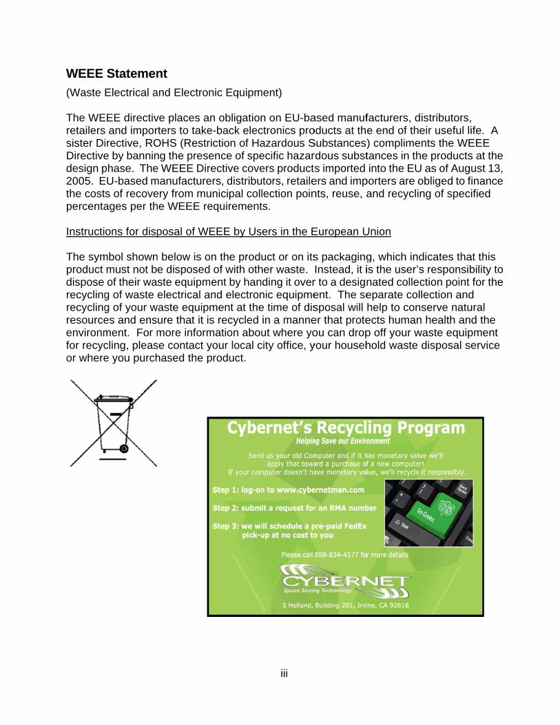
(Waste The WEretailerssister DiDirectivedesign p2005. Ethe costpercenta Instructi The symproduct dispose recyclingrecyclingresourceenvironmfor recycor where
Statemen
Electrical a
EEE directivs and imporirective, ROe by banninphase. TheEU-based m
s of recoveages per th
ons for disp
mbol shownmust not bof their wa
g of waste g of your wes and ensment. For mcling, please you purch
nt
and Electron
ve places arters to takeOHS (Restrng the presee WEEE Dirmanufactureery from muhe WEEE re
posal of WE
n below is oe disposedste equipmelectrical a
waste equipure that it ismore informse contact yhased the p
nic Equipm
n obligatione-back elecriction of Haence of sperective coveers, distribuunicipal collequirement
EEE by Us
on the produd of with othment by hanand electronment at thes recycled
mation abouyour local cproduct.
iii
ment)
n on EU-bactronics proazardous Secific hazarers producttors, retailelection points.
ers in the E
uct or on itsher waste. ding it over
nic equipmee time of disin a manneut where yo
city office, y
ased manufoducts at thSubstancesrdous substs imported
ers and impnts, reuse, a
European U
s packagingInstead, it ir to a designent. The sesposal will er that proteou can dropyour househ
facturers, de end of th) complimetances in thinto the EU
porters are oand recycli
Union
g, which indis the user’snated colleeparate colhelp to conects humanp off your whold waste
distributors,eir useful li
ents the WEhe productsU as of Auguobliged to fing of speci
dicates thas responsibction point llection and
nserve natun health andwaste equip
disposal se
ife. A EEE s at the ust 13, inance ified
at this bility to for the
d ural d the
pment ervice
iv
TABLE OF CONTENTS FCC-B Radio Frequency Interference Statement ...................................................................... i
Trademarks ................................................................................................................................... i
Safety Instructions ...................................................................................................................... ii
WEEE Statement ........................................................................................................................ iii
Introduction ................................................................................................................................. 1
LCD-PC C22 Series Specifications ............................................................................................ 1
Processor Support .................................................................................................................. 1
Motherboard Core Logic ...................................................................................................... .. 1
Memory Support ...................................................................................................................... 1
Networking ............................................................................................................................... 1
Audio ......................................................................................................................................... 1
Hard Disk Drive ........................................................................................................................ 2
Mounting ................................................................................................................................... 2
LCD Panel ................................................................................................................................. 2
Expansion Slots ....................................................................................................................... 2
Front Lower Right Bezel ......................................................................................................... 2
Right Side Bezel ....................................................................................................................... 2
Left Side Bezel ......................................................................................................................... 2
Bottom I/O Panel ..................................................................................................................... 3
Power Supply ........................................................................................................................... 3
Dimensions .............................................................................................................................. 3
Power Management .................................................................................................................... 8
Waking the System Up .......................................................................................................... 10
Energy Saving Tips ............................................................................................................... 10
C22 Series Overview……...…………..…………………………………...…………………………11
On Screen Display Buttons………………………………………………………………………….14
On Screen Display Usage ..................................................................................................... 15
System Assembly ..................................................................................................................... 20
Necessary Tools ................................................................................................................... 20
Orientation of Key Parts ........................................................................................................ 21
C22 Series Disassembly ....................................................................................................... 22
Installing the CPU .................................................................................................................. 24
Installing the CPU Heat Sink ................................................................................................. 25
v
Installing the Memory Module DDR3 SO-DIMM .................................................................. 26
Installing the Hard Disk Drive ............................................................................................... 27
Installing the Optical Disk Drive ........................................................................................... 28
Installing the Mini-PCIe Card (Optional) .............................................................................. 30
Installing the Cover ............................................................................................................... 31 Cybernet Recycling SOP…………………………………………………………………………….33
Figures Figure 1: Front View with Optional Webcam………….…………………………….....……..……11
Figure 2: Left side view with Optical Drive……………………………………………....…..…….12
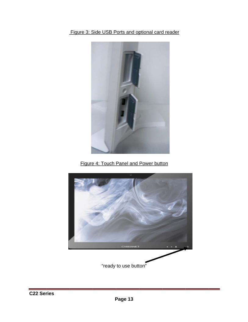
Figure 3: Side USB Ports and optional card reader.…………………………………......………13
Figure 4: Touch Panel and Power Button………..……..………………..……………….....……..13
Figure 5: On Screen Display Buttons…………………...…..…………..…………….…..…………14
Figure 6: On Screen Display Icons……………………...…..…………..…………….…..………...15
Figure 7: Back view….. ......................................................................................................... …18
Figure 8: Bottom Panel I/O Ports ............................................................................................. 18
Figure 9: Ctrl+Alt+Del button .................................................................................................. 19
Figure 10: CPU Heat Sink Ventilation Fan .............................................................................. 19
Figure 11: System Fans, CPU Heat Sink Fan and Ventilation............................................... 21
Figure 12: Open system .......................................................................................................... 23
Figure 13: Open system with GPU ......................................................................................... 23
C22 Series Page 1
Introduction
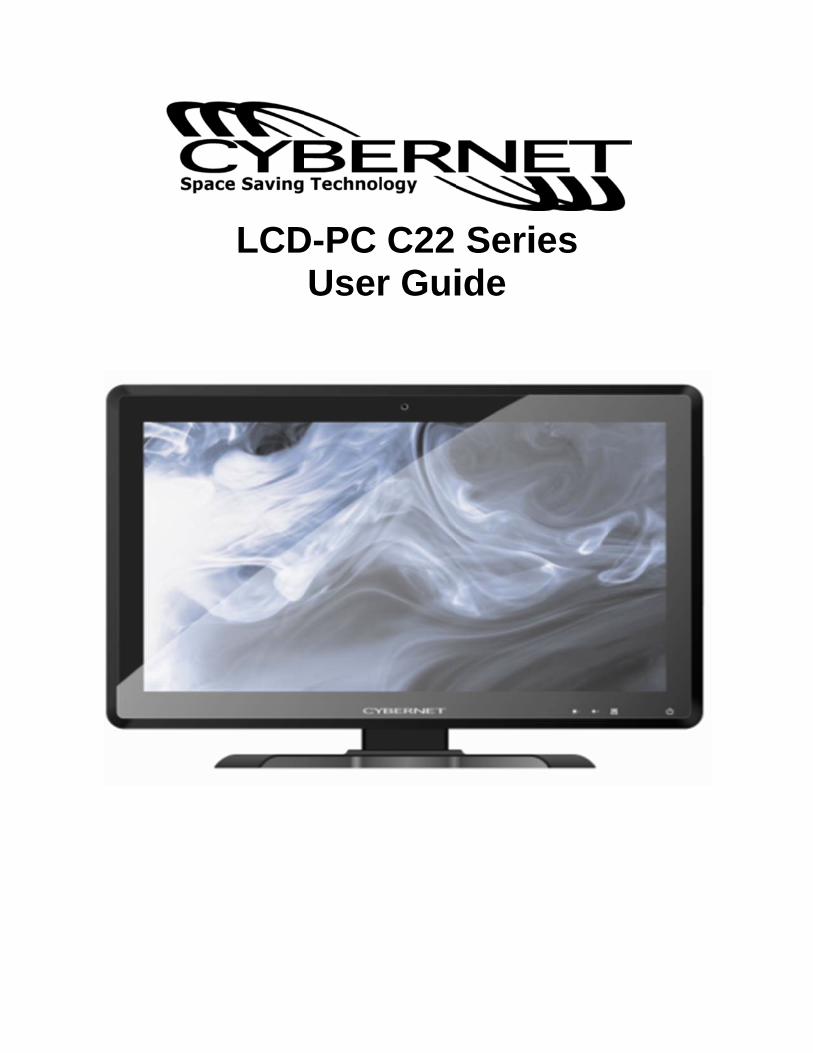
Congratulations for purchasing the C22 Series. The LCD-PC C22 Series is your best Slim LCD PC choice. With the fantastic appearance and small form factor, it can easily be set anywhere. The feature packed platform also gives you an exciting PC experience.
C22 Series Specifications
Processor Support 4th generation Intel® Core™ i3 i5 and Core™ i7 in the LGA1150 package up to 35W (Max 65W for IGD version).
Motherboard Core Logic Intel® H81 Express chipset (Haswell)
Memory Support DDR3 1333/1600 MHz SO-DIMM SDRAM (Un-buffered Non-ECC) 2 DDR3 1333/1600 MHz SO-DIMM slots (8GB Max) with 1.5V.
Video & Graphics Intel® integrated H81 Chipset with Intel® HD Graphics Intel GMA HD/Intel Clear Video HD Technology Built-in support for 1080p HD video playback, HDMI 1.4 & Blu-ray 3D support Supports Microsoft® DirectX 11.1, OpenCL 1.2 and OpenGL 4.0. DVMT allocated as needed from 128MB to 1.70GB Maximum display resolution 2560 x 1600.
Video & Graphics for dedicate Nvidia GPU Onboard NVIDIA GeForce N14M-GE GPU 2.0GB sDDR3 128-bit RAM 1080p HD video playback, HDMI 1.4 & Blu-ray 3D support. Supports Microsoft® DirectX 11, Shader Model 5.0 and OpenGL 4.1 Maximum display resolution 2560 x 1600.
Networking Supports 2 PCI Express LAN 10/100/1000 Fast Ethernet by Intel I217V Clarkville-V and Realtek RTL8111G
Audio 2 internal speakers with 78dB+/-3dB @ 2.0W HD Audio Codec Realtek® ALC892 Flexible 10-channel audio with jack sensing, Compliant with Azalia 1.0 Spec
C22 Series Page 2
Hard Disk Drive Optional two 2.5” SATA III Hard Disk Drive or SATA SSD - Any Capacity
RFID Reader Optional one 125KHz or one 13.56MHz.
Wall Mount Support 75x75mm / 100x100mm VESA mounting hole, using M4 screw. The 75x75mm can support max screw length of 12mm; and 100x100mm can support max screw length of 16mm.
Swivel Stand System Base enables left/right rotation up to 60 degrees, tilt from -5 to 60 degrees.
LCD Panel 21.5" LED widescreen 16:9 format display (1920x1080). Optional Touch Screen Ten-finger Multi-touch P-cap solution. Webcam Optional 3.0 Megapixel Camera Expansion Slots Two mini-PCIe (One full size and one half size) Wireless Optional 802.11 b/g/n + Bluetooth or 802.11 a/b/g/n + Bluetooth
Front Lower Right Bezel Power On/Off Buttons Display On/Off Adjust and also function as Menu Button Contrast Adjust Brightness Adjust
Right Side Bezel Two USB 2.0 ports (for mouse and keyboard) Optional card reader
Left Side Bezel Optional one optical tray type disk drive – 2.5” slim or optional one additional 2.5” SATAII HDD/SSD.
C22 Ser
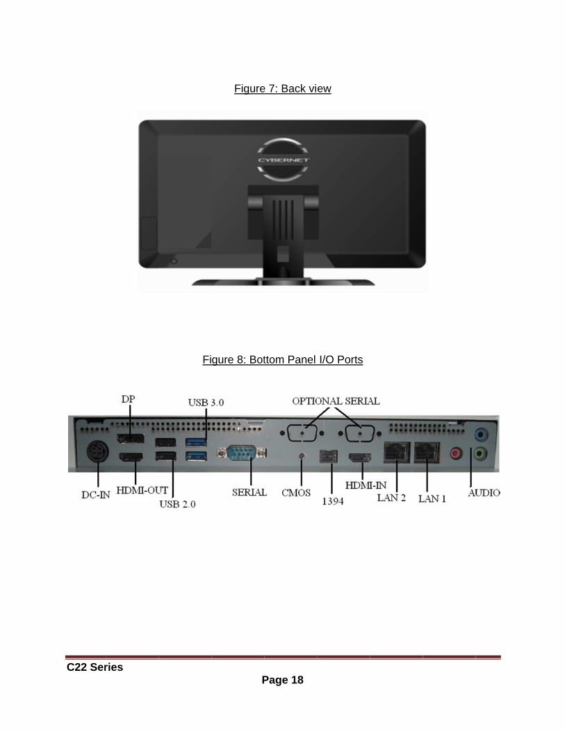
Bottom1 Ctrl+A1 DC/IN2 USB2HDMI-INMic in 4 TV TuAudio Le
Power 120 WatDC Outp InternaOptiona
Dimen598mm 598mm
ries
m I/O PanAlt+Del butto
port, 1 HD.0 ports, 2 N port, 1 Re
ner ports - eft & Audio
r Supply tt Power Adput: 19V, 6
al Batteryal battery
nsions (H) x 420m(H) x 377m
nel on
DMI-OUT poUSB3.0 poealtek LAN
Optional wo Right),
dapter, AC 6.32A or 12
y to last 20
mm (W) x 26mm (W) x 55
ort, 1 DP poorts, 1 Seria
port, 1 Inte
with TV Tun
Input: 100~2V, 10.00A
0 mins dep
62 mm (D)5 mm (D) (w
Page 3
ort al port, 1 CMl LAN port,
er (COAX C
~240V AC,120W
pending o
(with standwithout sta
MOS clear 3 Audio jac
Cable In, R
2A, 50-60W Max.
on system
d) and)
button, 1 1cks – Line i
RCA Compo
Hz
m usage/lo
394 port, 1in, Line Out
osite Video
oading.
t and
o In,
C22 Series Page 4
Intended use The C22 Series is designed for general pc application purpose for hospital environment and for diagnosis. It could be used for Radiology, PACS (Picture Archiving Communication Systems), LIS (Lab Information Systems) and Electronic Record purpose. It shall not be used for life-supporting system. WARNING: Critical diagnostic decision must not be based solely on images displayed by this device. Unpacking After opening the carton, there is the LCD PC with an accessory box. Check carefully to see if there are any damages or missing parts. Read the Manual Please read this manual carefully and remember to keep this manual for future reference. Safety Instructions & Cleaning This product has undergone various tests in order to comply with safety standards. Inappropriate use or open the housing may be dangerous. Please remember to follow the instructions below to ensure your safety during the installation and operating process. Transporting & Placement of unit 1. When moving the unit on a cart; be very cautious. Quick stops, excessive forces and uneven surfaces may cause the cart to overturn thus risking the unit to fall to the ground. 2. If the LCD PC unit does fall to the ground, immediately turn the power off and disconnect cords. Then contact a service technician for repairs. Continual use of the unit may result cause a fire or electric shock. Also, do not repair the unit on your own. 3. Having two or more people transporting the LCD PC unit is recommended. In addition, when installing the unit by suspending it also requires two or more people. 4. Before suspending the unit, make sure the material used for suspension is sturdy and stable. If not properly suspended, the LCD PC unit may fall and cause serious injury to people standing nearby as well as to the unit itself. 5. If the user wishes to mount the LCD PC unit, remember to use only the mounting hardware recommended by the manufacturer.

C22 Series Page 5
Electrical and Power Source Related 1. This LCD PC unit must operate on a power source as shown on the specification label. If you are not sure what type of power supply used in the area, consult your dealer or local power supplier. 2. The power cords must not be damaged. Applied pressure, added heat, and tugging may damage the power cord. 3. The power cord must be routed properly when setup takes place. We advise that this aspect measure is to prevent people from stepping on the cords or while the unit is suspended to prevent flying objects from getting tangled with the unit. 4. Do not overload the AC outlets or extension cords. Electrical shocks or fires may occur from overloading. 5. Do not touch the power source during a thunderstorm. 6. If your hands are wet, do not touch the plug. 7. Use your thumb and index finger, grip firmly on the power cord to disconnect from the electrical socket. By pulling the power cord, may result in damaging it. 8. If the unit is not going to be in use for an extended period of time, remember to disconnect the unit. 9. The LCD PC unit uses 19V DC output from an adapter. Connect the unit to a power source with the same numerical value as indicated. Please use only the power cord provided by the dealer to ensure safety and EMC compliance. WARNING: To avoid risk of electric shock, this equipment must only be connected to a supply mains with protective earth. Various Factors of Environment 1. Operating Temperature: 0°C to 40°C ; Non-operating temperature: -20°C to 60°C. 2. Operating Humidity (Non-Condensing): 10% to 90%. Non-operating Humidity (Non-condensing): 10% to 90%. 3.Do not insert objects into the openings. 4. Do not have liquids seep into the internal areas of the LCD PC unit. 5. Having liquids seep in or inserting objects into the unit may result in electric shocks
C22 Series Page 6
from taking and/or short circuiting the internal parts. 6. Do not place the LCD PC unit in the presence of high moisture areas. 7. Do not install the LCD PC unit in a wet environment. 8. Do not place unit near heat generating sources. 9. Do not place the unit in a location where it will come in contact with fumes or steam. 10. Remember to keep the LCD PC unit away from the presence of dust. 11. If water has flow in or seep in, immediately disconnect the open frame unit. Then contact a service technician for repairs. Ventilation Spacing 1. Do not cover or block the openings on the top and back sides of the LCD PC unit. Inadequate ventilation may cause overheating thus reducing the lifespan of the unit. 2. Unless proper ventilation is present, do not place unit in an enclosed area; such as a built-in shelf. Keep a minimum distance of 10 cm between the LCD PC unit and wall. Cleaning the unit 1. Remember to turn off the power source and to unplug the cord from the outlet before cleaning the unit. 2. Carefully dismount the unit or bring the unit down from suspension to clean. 3. Please use a dry soft cloth to clean the unit. 4. Take a dry cloth and wipe the unit dry. Remember to avoid having liquids seep into the internal components and areas of the LCD PC unit. Servicing, Repairing, Maintenance & Safety Checks 1. If the unit is not functioning properly, observe the performance level of the LCD PC closely to determine what type of servicing is needed. 2. Do not attempt to repair the LCD PC unit on your own. Disassembling the cover exposes users’ to high voltages and other dangerous conditions. Notify and request a qualified service technician for servicing the unit. 3. To avoid risk of electric shock, this equipment must only be connected to a supply mains with protective earth.
C22 Ser
4. If anyThen co(a) A liqu(b) The (c) The u(d) If sm(e) If the(f) When 5. Whentechniciacharactemay res
ries
y of the folloontact a quauid was spiunit is soakunit is drop
moke or strae power corn the functio
n replacemeans use reperistics andult in startin
owing situatalified servicilled on the ked with liquped or dam
ange odor isrd or plug isons of the u
ent parts arplacement p performanng a fire, el
ISO 7000-0 ISO 7000-1for use.
IEC 60417
IEC 60417
EU-wide lethat waste must be disincludes mpower cordplease followhere you agreementelectronic pMember St
tions occur ce techniciaunit or obje
uids. maged. s flowing ous damaged.unit are dys
re needed fparts specif
nce as the oectrical sho
0434: Caut
1641: Follow
-5009: rea
-5031: Dire
egislation, aelectrical asposed of sonitors and
ds. When yoow the guidpurchased
ts made betproducts ontates.
Page 7
turn the poan. ects have fa
ut of the ope. sfunctional.
for the LCDfied by the original partock and/or o
ion, consult
w operating
ady to use.
ect current.
as implemenand electronseparately fd electrical aou need to
dance of yo the productween yournly applies t
ower source
allen into th
erating unit
D PC unit, mmanufacturts. If unauthother dange
t ACCOMP
g instructio
nted in eacnic productsfrom normaaccessoriesdispose of ur local autct, or if apprself. The mto the curre
e off and un
he unit.
t.
make sure srer, or thosehorized parers.
PANYING D
ns or Cons
ch Member s carrying tal househols, such as your panel
thority, or alicable, follo
mark on elecent Europea
nplug the u
service e with the srts are used
DOCUMENT
ult instructi
State, requthe mark (led waste. Thsignal cablel PC produc
ask the shopow any ctrical and an Union
nit.
same d it
TS.
ons
uires eft) his es or cts, p
C22 Ser
Power
Power mas well a To be enperiod o Power [Power Oyour dis
Then clic
ries
Managem
managemenas deliver e
nergy efficieof user inact
Managem
Options] in play and ha
ck on the [P
ment
nt of LCD-Penvironmen
ent, turn offtivity.
ment in W
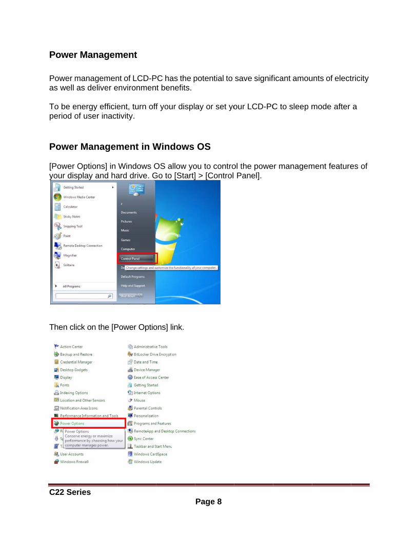
Windows Oard drive. G
Power Optio
PC has the pt benefits.
f your displ
Windows
OS allow yoGo to [Start]
ons] link.
Page 8
potential to
ay or set yo
OS
ou to contro] > [Control
save signif
our LCD-PC
ol the powe Panel].
ficant amou
C to sleep m
er managem
unts of elect
mode after
ment feature
tricity
a
es of
C22 Ser
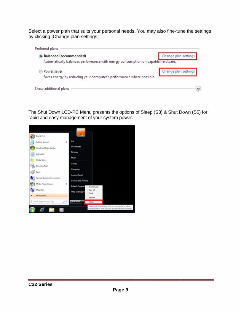
Select aby clicki
The Shurapid an
ries
a power planng [Change
ut Down LCd easy man
n that suits e plan settin
D-PC Menunagement o
your persongs].
u presents tof your syste
Page 9
onal needs.
the options em power.
. You may a
of Sleep (S
also fine-tu
S3) & Shut D
ne the setti
Down (S5) f
ings
for

C22 Series Page 10
Power Management through ENERGY STAR qualified Monitors (Not supply with the LCD PC)
The power management feature allows the LCD-PC to initiate a low-power or “Sleep” mode after a period of user inactivity. When used with an external ENERGY STAR qualified Monitor, this feature also supports similar power management features of the monitor. To take advantage of these potential energy saving, the power management feature can be set to behave in the following ways when the system is operating on AC power:
Turn off the display after 15 minutes. Initiate Sleep after 30 minutes.
Waking the System Up The LCD-PC shall be able to wake up from power saving mode in response to a command from any of the following:
the power button, the network (Wake on LAN), the mouse the keyboard
Energy Saving Tips:
Tune the settings in Power Options under Windows OS to optimize your LCD-PC’s power management.
Install power saving software to manage your PC’s energy consumption. Always disconnect the AC power cord or switch the wall socket off if your LCD-PC
would be left unused for a certain time to achieve zero energy consumption.
C22 Ser
ries
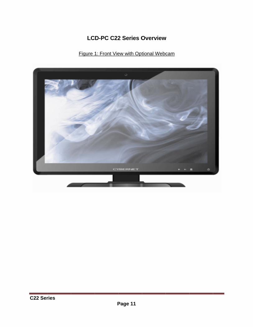
LC
Figure
P
D-PC C22
1: Front Vie
Page 11
2 Series O
ew with Opt
Overview
tional Webc
w
cam
C22 Ser
ries
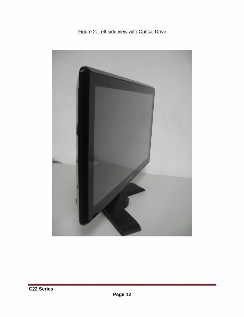
Figure
P
e 2: Left side
Page 12
e view with
h Optical Drrive
C22 Ser
ries
Figure 3: S
Figure
P
Side USB P
e 4: Touch
“ready
Page 13
Ports and op
Panel and
to use butt
ptional card
Power butt
ton”
d reader
ton
C22 Ser
On Scr
There a
OSD
Ready to
Menu button/Pbutton
Contras
Brightne
ries
reen Disp
re four butt
D key
o use D
Privacy im
t / + Im
ess / - Im
play ButtoFigu
tons on the
Respons
Delay 1.5 se
mmediately
mmediately
mmediately
P
ons ure 5: On S
lower beze
se time
ec
y
y
y
Page 14
creen Disp
el of the sc
On/off Pow
Firstly enteWhen turnoff the TouWhen turnthe Touchfrom sleep
Turn on th
Continuoukeep pressvalue
Turn on th
Continuoukeep pressvalue
play Buttons
reen. From
Fu
wer
er into Menn off the privuch function on the priv function a
p mode as w
he contrast
us send outsing the bu
he brightnes
us send outsing the bu
s
m right to le
unction
nu; Secondvacy buttonn as well. vacy buttonnd also wawell
adjustmen
t pulse wheutton and in
ss adjustme
t pulse wheutton and in
eft they are:
ly to confirmn- it will Tur
n, it will turnke up the u
t on display
n user’s finncrease the
ent on disp
n user’s finncrease the
:
m. rn
n on unit
y
nger e
play
nger e
C22 Ser
Base onout on thvalue byexit auto ContrasBrightne “I” show
ries
n the lower bhe display, y pressing +omatically i
t: Select toess: Select
ws informatio
O
Fig
bezel OSD once you d
+ or - , rangn a matter
toggle greto toggle g
on of curre
P
On Screen
gure 6: On S
key, the Wdecide the fue from zeroof 3 second
ater or lessreater or le
nt display s
Page 15
n Display
Screen Dis
When the Briunction youo(Min Valueds if no sele
ser contrastesser bright
setting.
y Usage
play Icons
ightness / +u need to ade) to 100(Mection is m
t. tness.
+ and Contrdjust, you cax Value). ade.
rast / - will ccould adjus The scree
come st the n will
C22 Ser
“Factory
“ShippinRe-plug Note: Neshippingplug in D
ries
y Default” re
ng Mode” wthe AC Po
ever unplugg mode settDC and/or A
esets monit
when it is “onwer if batte
g AC and/oting, pleaseAC power.
P
”Menu” to
tor to origin
n” it cuts thery support
r DC powee wait for ab
Page 16
select lang
al settings.
e power frois require.
r until Windbout 20 secs
guage.
.
om battery o
dows shut ds before bo
or no batte
down normaooting up sy
ry support.
ally. After ystem even after
C22 Ser
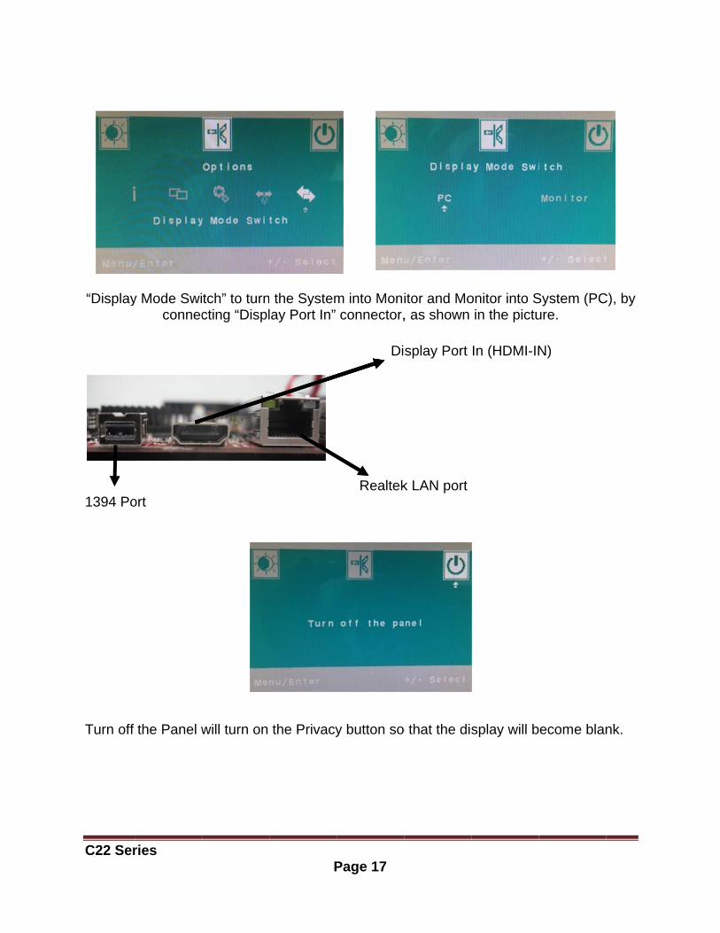
“Display
1394 Po Turn off
ries
y Mode Swiconnec
ort
the Panel w
tch” to turncting “Displ
will turn on
P
the Systemlay Port In”
the Privacy
Page 17
m into Moniconnector,
Di
Realtek
y button so
itor and Mo, as shown
splay Port
k LAN port
o that the dis
onitor into Sin the pictu
In (HDMI-IN
splay will b
System (PCure.
N)
ecome blan
C), by
nk.
C22 Ser
ries
Fi
P
Figure
gure 8: Bot
Page 18
e 7: Back vi
ttom Panel
ew
I/O Ports
C22 Ser
ries
Figure
P
Figure 9: C
e 10: CPU H
Page 19
Ctrl+ Alt+De
Heatsink Ve
el button
entilation FFan

C22 Ser
System
This chaany instcarefullycompon This chahard dis
Necess
ries
m Assemb
apter providallation, usy follow all ients.
apter will incsk drive (HD
sary Too
A Pa m
Pliecab
Forcejump
Rubb
Electr
Pap
bly
des systeme a groundinstallation
clude instruDD), optical
ls
Phillips scremagnetic he
ers can be ubles.
eps/tweezepers.
ber gloves c
ric screwdri
per clip to be
P
assembly ed wrist strprocedures
uctions for hl disk drive
ewdriver canead is recom
used as an
ers can be u
can preven
iver can be
e used to e
Page 20
informationrap before s. Static el
how to insta(ODD), mi
n be used tommended.
auxiliary to
used to pic
t injury from
e used to se
eject the OD
n and procehandling colectricity ma
all CPU, heni-PCIE ca
o do most oApplied ma
ool to conne
ck up tiny sc
m static cha
ecure all sc
DD when S
Sys
edures. Whomputer coay damage
eat sink, merd.
of the installaximum torq
ect some c
crews or se
arge.
crews more
System is po
stem Assem
hile performomponents e the
emory mod
lation. Oneque is 5kg.
connectors
et up the
quickly.
ower off.
mbly
ming and
ules,
e with
or
C22 Ser
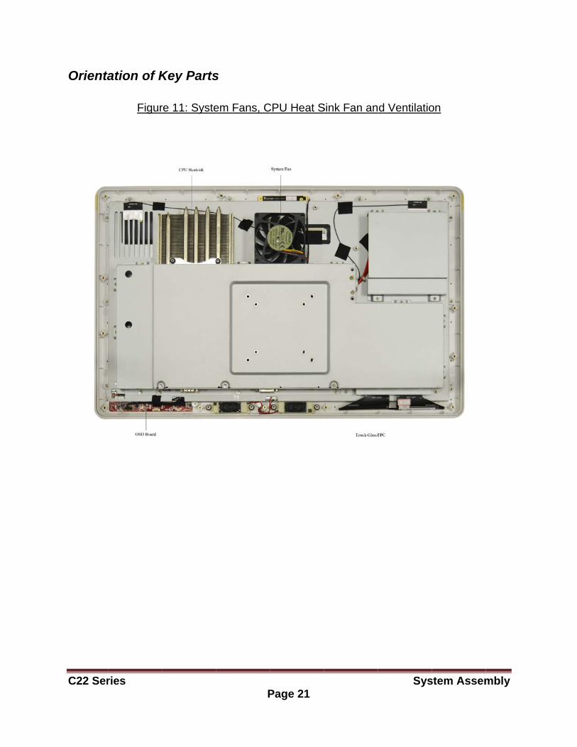
Orienta
ries
ation of K
Figur
Key Parts
re 11: Syste
P
s
em Fans, C
Page 21
CPU Heat S
Sink Fan an
Sys
d Ventilatio
stem Assem
on
mbly
C22 Series System Assembly Page 22
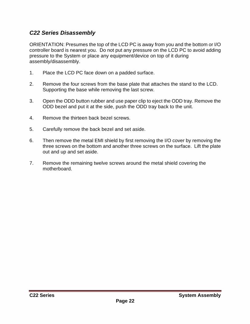
C22 Series Disassembly ORIENTATION: Presumes the top of the LCD PC is away from you and the bottom or I/O controller board is nearest you. Do not put any pressure on the LCD PC to avoid adding pressure to the System or place any equipment/device on top of it during assembly/disassembly. 1. Place the LCD PC face down on a padded surface. 2. Remove the four screws from the base plate that attaches the stand to the LCD.
Supporting the base while removing the last screw.
3. Open the ODD button rubber and use paper clip to eject the ODD tray. Remove the ODD bezel and put it at the side, push the ODD tray back to the unit.
4. Remove the thirteen back bezel screws. 5. Carefully remove the back bezel and set aside. 6. Then remove the metal EMI shield by first removing the I/O cover by removing the
three screws on the bottom and another three screws on the surface. Lift the plate out and up and set aside.
7. Remove the remaining twelve screws around the metal shield covering the
motherboard.
C22 Ser
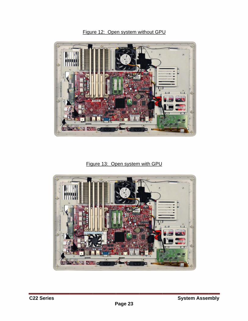
ries
Figur
Fig
P
re 12: Ope
ure 13: Op
Page 23
en system w
pen system
without GP
m with GPU
Sys
U
stem Assem
mbly
C22 Ser
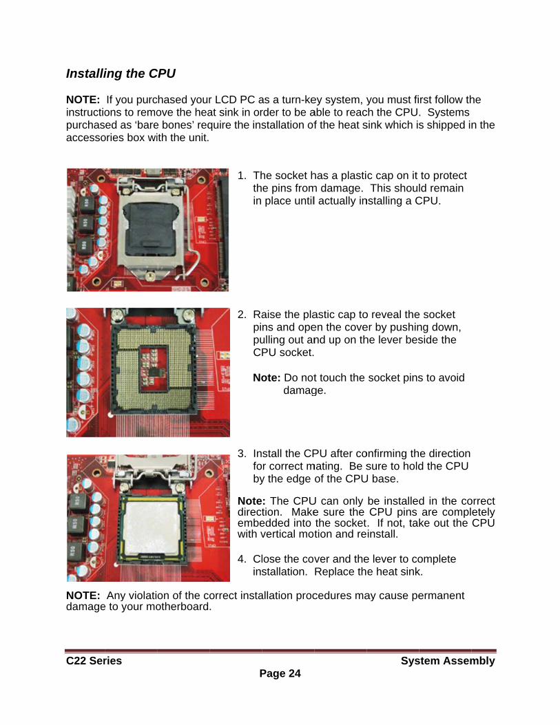
Installi NOTE: instructiopurchasaccesso
NOTE: damage
ries
ing the C
If you purcons to remoed as ‘bare
ories box wi
Any violatie to your mo
CPU
chased yourove the heae bones’ reqith the unit.
on of the cootherboard
P
r LCD PC aat sink in orquire the ins
1. Th th in
2. Ra pi pu C No
3. In fo by
Notedirectembewith v 4. Cl ins
orrect insta.
Page 24
as a turn-kerder to be astallation of
he socket he pins fromplace until
aise the plans and opeulling out anPU socket.
ote: Do not damag
stall the CPr correct m
y the edge
: The CPUtion. Makeedded into vertical mot
lose the covstallation.
allation proc
ey system, yable to reacf the heat s
has a plastim damage.l actually in
astic cap toen the covend up on th
t touch the ge.
PU after comating. Be s
of the CPU
U can only e sure the the sockettion and re
ver and theReplace th
cedures ma
Sys
you must fich the CPUsink which is
c cap on it This shoul
nstalling a C
o reveal theer by pushinhe lever bes
socket pins
onfirming thsure to hold
U base.
be installedCPU pins . If not, takinstall.
e lever to coe heat sink
ay cause pe
stem Assem
rst follow th. Systems s shipped i
to protect ld remain
CPU.
e socket ng down, side the
s to avoid
e directiond the CPU
d in the coare compl
ke out the
omplete k.
ermanent
mbly
he
n the
orrect etely CPU
C22 Ser
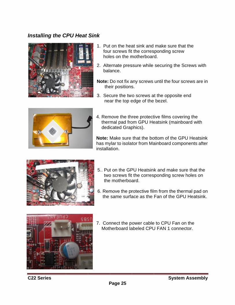
Installi
ries
ing the C
CPU Heat
P
Sink
1. Put fou hole
2. Alte bala Note: the
3. Sec nea
4. Rem therm dedi Note: Mhas myinstalla
5.. Put two the 6. Rem the
7. Con Moth
Page 25
t on the hear screws fites on the m
ernate presance.
Do not fix aeir positions
cure the twoar the top e
move the thmal pad froicated Grap
Make sure ylar to isolaation.
t on the GPo screws fit e motherboa
move the prsame surfa
nnect the pherboard la
at sink and t the corresmotherboar
ssure while
any screws s.
o screws aedge of the
ree protectom GPU Hephics).
that the botor from Ma
PU Heatsint the corresard.
rotective filace as the
ower cableabeled CPU
Sys
make suresponding scrd.
securing th
until the fou
at the oppos bezel.
tive films coeatsink (ma
ottom of theainboard co
k and makesponding sc
m from the Fan of the
e to CPU FaU FAN 1 co
stem Assem
e that the crew
he Screws
ur screws a
site end
overing the ainboard wi
e GPU Heaomponents
e sure that crew holes
thermal paGPU Heats
an on the onnector.
mbly
with
are in
ith
tsink after
the on
ad on sink.
C22 Ser
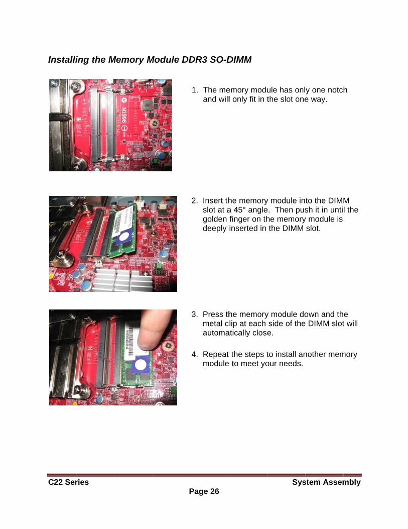
Installi
ries
ing the M
Memory M
P
Module DD
Page 26
DR3 SO-D
1. The me and will
2. Insert th slot at a golden deeply
3. Press th metal c automa
4. Repeat module
DIMM
emory modul only fit in t
he memorya 45° anglefinger on thinserted in
he memorylip at each
atically close
the steps te to meet yo
Sys
ule has onlthe slot one
y module ine. Then pushe memorythe DIMM
y module doside of thee.
to install anour needs.
stem Assem
y one notce way.
to the DIMMsh it in unti
y module is slot.
own and the DIMM slot
nother mem
mbly
h
M l the
e t will
mory
C22 Ser
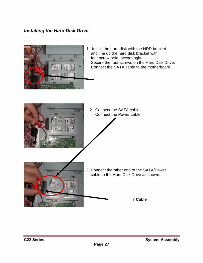
Installi
ries
ing the H
Hard Disk
P
Drive
1. In an fou Se Co
2.
3. Co ca
.
Page 27
nstall the hand line up thur screw hoecure the foonnect the S
Connect thConnect th
onnect the oble to the H
SATA Ca
SA
ard disk withe hard disole accordiour screwsSATA cabl
he SATA cahe Power ca
other end oHard Disk D
ble
ATA/Powe
Sys
h the HDD k bracket wingly. on the Hare to the mo
able, able
of the SATADrive as sh
er Cable
stem Assem
bracket with
rd Disk Drivotherboard.
A/Power own.
mbly
ve. .
C22 Ser
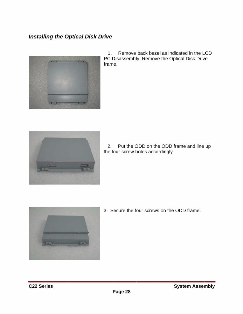
Installi
ries
ing the O
Optical Dis
P
sk Drive
1.PC Dfram
2.the fo
3. S
Page 28
Remove Disassemble.
Put the Oour screw h
ecure the fo
back bezely. Remove
ODD on theholes accor
our screws
Sys
el as indicate the Optica
e ODD framrdingly.
s on the OD
stem Assem
ted in the Lal Disk Driv
me and line
DD frame.
mbly
LCD ve
up
C22 Ser
ries P
P
s
fr
Page 29
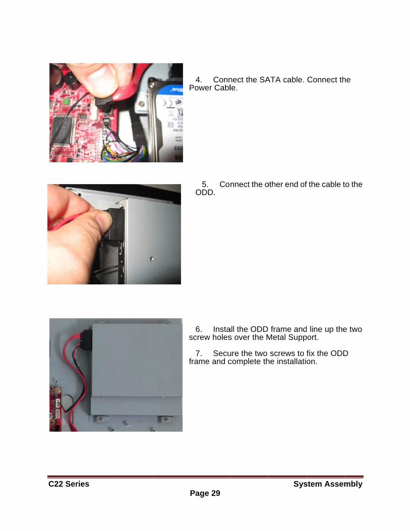
4. ConnPower Cabl
5. CoODD.
6. Instascrew holes
7. Securame and c
nect the SAle.
nnect the o
all the ODD s over the M
ure the two complete th
Sys
ATA cable.
other end of
frame andMetal Supp
screws to fhe installatio
stem Assem
Connect th
f the cable t
line up theport.
fix the ODDon.
mbly
he
o the
e two
D

C22 Ser
Installi
ries
ing the M
Mini-PCIe
P
Card (Op
2
Page 30
ptional)
1. The min notch an Insert th Then, p fingers o deeply i slots.
2. Press do and sec
ni-PCIe cardnd will onlyhe mini-PCIush it in unon the mininserted in
own the micure with th
Sys
ds have ony fit in one wIe card at a
ntil the goldi-PCIe cardthe mini-PC
ini-PCIe cae small scr
stem Assem
nly one way. a 45° angleen
d are CIe
ard rews.
mbly
.
C22 Ser
Installi
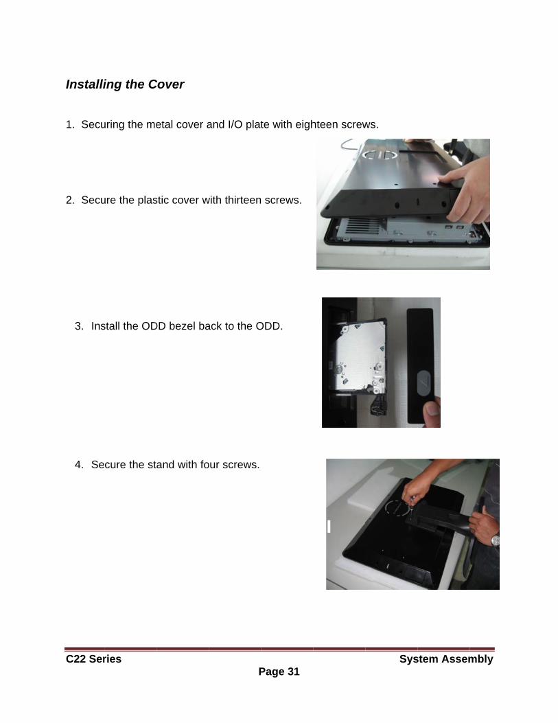
1. Secu 2. Secu
3. Ins
4. Se
ries
ing the C
uring the me
ure the plas
stall the OD
cure the st
Cover
etal cover a
stic cover w
DD bezel ba
and with fo
P
and I/O plat
with thirteen
ack to the O
our screws.
Page 31
te with eigh
screws.
ODD.
hteen screw
Sys
ws.
stem Assemmbly
C22 Ser
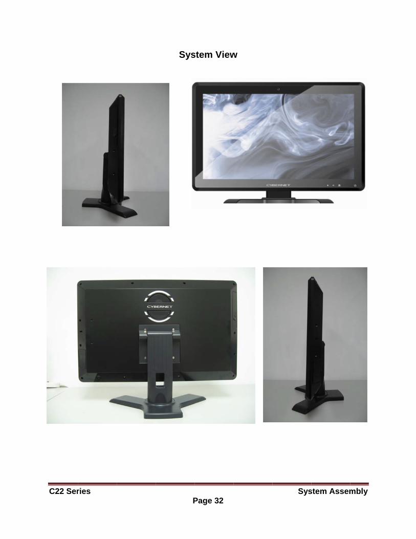
ries P
Sys
Page 32
stem View
w
Sysstem Assemmbly
C22 Ser
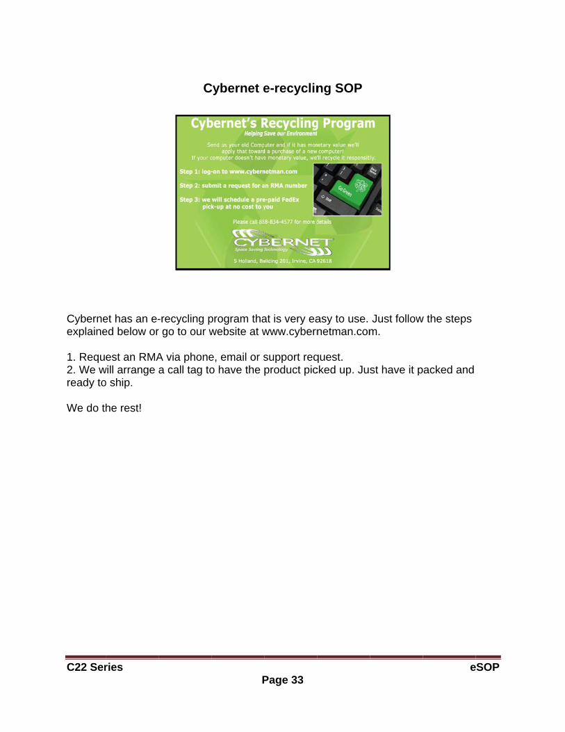
Cyberneexplaine 1. Requ2. We wready to We do th
ries
et has an e-ed below or
est an RMAwill arrange o ship.
he rest!
C
-recycling pr go to our w
A via phonea call tag to
P
Cybernet e
program thawebsite at w
e, email or so have the
Page 33
e-recyclin
at is very eawww.cybern
support reqproduct pic
ng SOP
asy to use. netman.com
quest. cked up. Jus
Just followm.
st have it p
e
w the steps
packed and
eSOP