Embed Size (px)
Citation preview
4D SYSTEMS
µLCD-32PT(GFX)3.2” LCD Display ModuleData Sheet
Document Date: 22nd July 2010Document Revision: 3.0
© 2010 4D Systems www.4dsystems.com.au Page 1 of 24
4D SYSTEMS
µLCD-32PT(GFX)3.2” Display Module
Data Sheet
Description
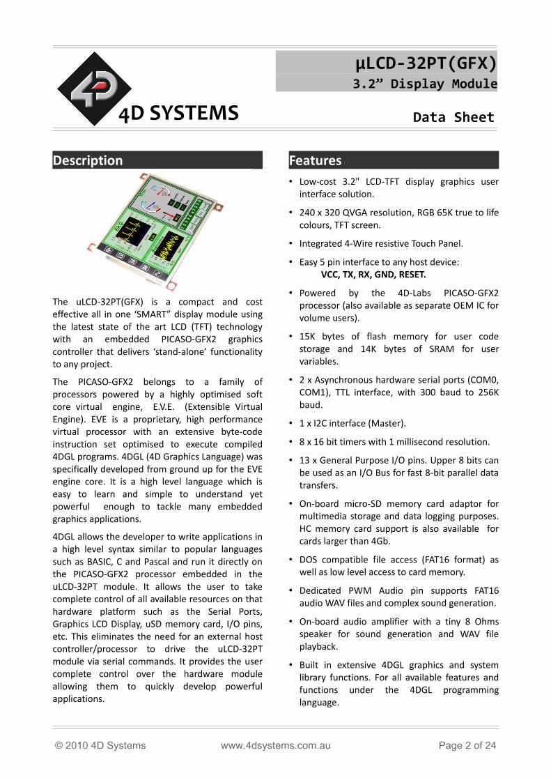
The uLCD-32PT(GFX) is a compact and cost effective all in one ‘SMART” display module using the latest state of the art LCD (TFT) technology with an embedded PICASO-GFX2 graphics controller that delivers ‘stand-alone’ functionality to any project.
The PICASO-GFX2 belongs to a family of processors powered by a highly optimised soft core virtual engine, E.V.E. (Extensible Virtual Engine). EVE is a proprietary, high performance virtual processor with an extensive byte-code instruction set optimised to execute compiled 4DGL programs. 4DGL (4D Graphics Language) was specifically developed from ground up for the EVE engine core. It is a high level language which is easy to learn and simple to understand yet powerful enough to tackle many embedded graphics applications.
4DGL allows the developer to write applications in a high level syntax similar to popular languages such as BASIC, C and Pascal and run it directly on the PICASO-GFX2 processor embedded in the uLCD-32PT module. It allows the user to take complete control of all available resources on that hardware platform such as the Serial Ports, Graphics LCD Display, uSD memory card, I/O pins, etc. This eliminates the need for an external host controller/processor to drive the uLCD-32PT module via serial commands. It provides the user complete control over the hardware module allowing them to quickly develop powerful applications.
Features• Low-cost 3.2" LCD-TFT display graphics user
interface solution.
• 240 x 320 QVGA resolution, RGB 65K true to life colours, TFT screen.
• Integrated 4-Wire resistive Touch Panel.
• Easy 5 pin interface to any host device: VCC, TX, RX, GND, RESET.
• Powered by the 4D-Labs PICASO-GFX2 processor (also available as separate OEM IC for volume users).
• 15K bytes of flash memory for user code storage and 14K bytes of SRAM for user variables.
• 2 x Asynchronous hardware serial ports (COM0, COM1), TTL interface, with 300 baud to 256K baud.
• 1 x I2C interface (Master).
• 8 x 16 bit timers with 1 millisecond resolution.
• 13 x General Purpose I/O pins. Upper 8 bits can be used as an I/O Bus for fast 8-bit parallel data transfers.
• On-board micro-SD memory card adaptor for multimedia storage and data logging purposes. HC memory card support is also available for cards larger than 4Gb.
• DOS compatible file access (FAT16 format) as well as low level access to card memory.
• Dedicated PWM Audio pin supports FAT16 audio WAV files and complex sound generation.
• On-board audio amplifier with a tiny 8 Ohms speaker for sound generation and WAV file playback.
• Built in extensive 4DGL graphics and system library functions. For all available features and functions under the 4DGL programming language.
© 2010 4D Systems www.4dsystems.com.au Page 2 of 24
µLCD-32PT(GFX) Data Sheet
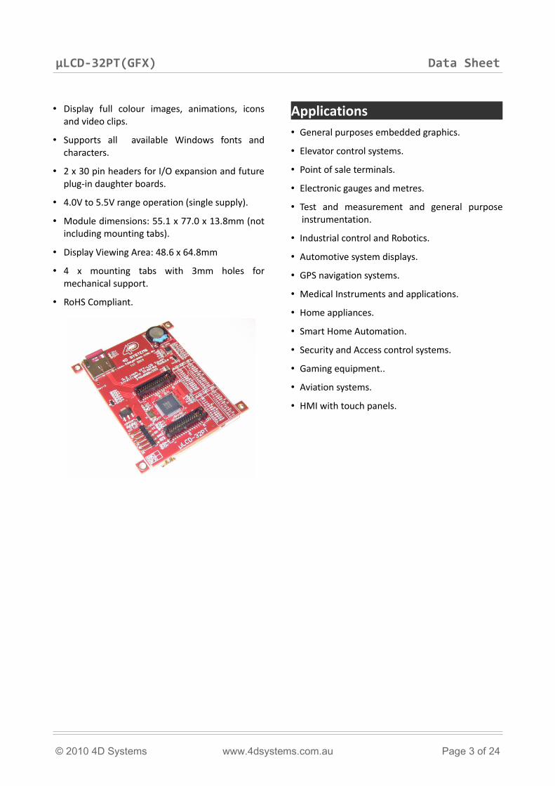
• Display full colour images, animations, icons and video clips.
• Supports all available Windows fonts and characters.
• 2 x 30 pin headers for I/O expansion and future plug-in daughter boards.
• 4.0V to 5.5V range operation (single supply).
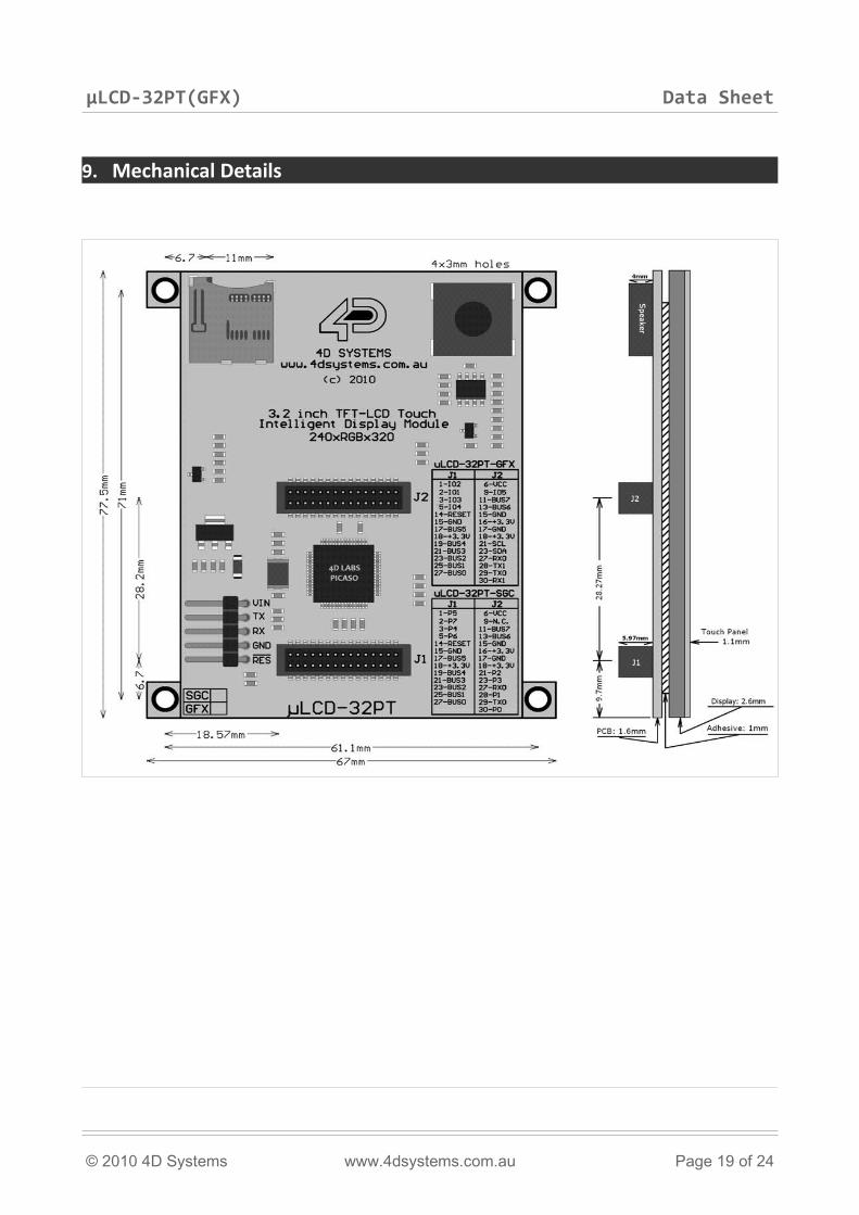
• Module dimensions: 55.1 x 77.0 x 13.8mm (not including mounting tabs).
• Display Viewing Area: 48.6 x 64.8mm
• 4 x mounting tabs with 3mm holes for mechanical support.
• RoHS Compliant.
Applications• General purposes embedded graphics.
• Elevator control systems.
• Point of sale terminals.
• Electronic gauges and metres.
• Test and measurement and general purpose instrumentation.
• Industrial control and Robotics.
• Automotive system displays.
• GPS navigation systems.
• Medical Instruments and applications.
• Home appliances.
• Smart Home Automation.
• Security and Access control systems.
• Gaming equipment..
• Aviation systems.
• HMI with touch panels.
© 2010 4D Systems www.4dsystems.com.au Page 3 of 24
µLCD-32PT(GFX) Data Sheet
Table of Contents1. Pin Configuration and Summary.............................................................................................................52. Hardware Interface - Pins.......................................................................................................................7
2.1 Serial Ports - COM0, COM1 UARTS ........................................................................................................72.2 GPIO - General Purpose IO Interface .....................................................................................................82.3 System Pins............................................................................................................................................8
3. Software Platform - 4DGL.......................................................................................................................94. PmmC Programming.............................................................................................................................135. Module Features...................................................................................................................................13
5.1 The Display – 3.2” TFT..........................................................................................................................135.2 The PICASO-GFX2 Processor................................................................................................................145.3 The uSD Memory Card.........................................................................................................................145.4 The Audio.............................................................................................................................................145.5 The Touch Screen.................................................................................................................................14
6. Memory Cards – FAT16 Format.............................................................................................................157. Display Precautions..............................................................................................................................158. Development and Support Tools...........................................................................................................16
8.1 PmmC Loader – PmmC Programming Software Tool ..........................................................................168.2 microUSB – PmmC Programming Hardware Tool.................................................................................168.3 Graphics Composer – Software Tool....................................................................................................168.4 FONT Tool – Software Tool...................................................................................................................168.5 RMPET – Software Tool........................................................................................................................178.6 4DGL-Workshop3 – Complete IDE Editor, Compiler, Linker, Downloader............................................178.7 Expansion Board : P1-EB......................................................................................................................18
9. Mechanical Details...............................................................................................................................1910. Reference Design................................................................................................................................2011. Specifications and Ratings..................................................................................................................22Proprietary Information............................................................................................................................24Disclaimer of Warranties & Limitation of Liability.....................................................................................24Contact Information..................................................................................................................................24
© 2010 4D Systems www.4dsystems.com.au Page 4 of 24
µLCD-32PT(GFX) Data Sheet
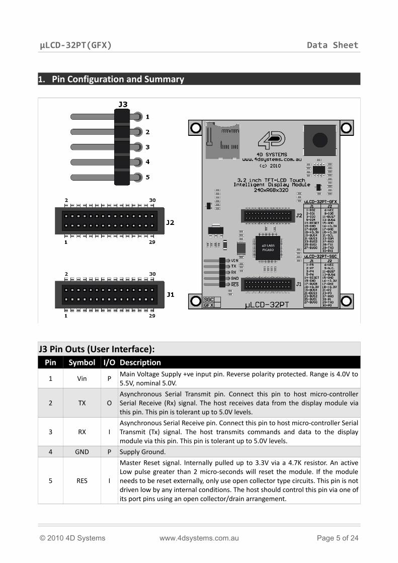
1. Pin Configuration and Summary
J3 Pin Outs (User Interface):Pin Symbol I/O Description
1 Vin PMain Voltage Supply +ve input pin. Reverse polarity protected. Range is 4.0V to 5.5V, nominal 5.0V.
2 TX OAsynchronous Serial Transmit pin. Connect this pin to host micro-controller Serial Receive (Rx) signal. The host receives data from the display module via this pin. This pin is tolerant up to 5.0V levels.
3 RX IAsynchronous Serial Receive pin. Connect this pin to host micro-controller Serial Transmit (Tx) signal. The host transmits commands and data to the display module via this pin. This pin is tolerant up to 5.0V levels.
4 GND P Supply Ground.
5 RES I
Master Reset signal. Internally pulled up to 3.3V via a 4.7K resistor. An active Low pulse greater than 2 micro-seconds will reset the module. If the module needs to be reset externally, only use open collector type circuits. This pin is not driven low by any internal conditions. The host should control this pin via one of its port pins using an open collector/drain arrangement.
© 2010 4D Systems www.4dsystems.com.au Page 5 of 24
µLCD-32PT(GFX) Data Sheet
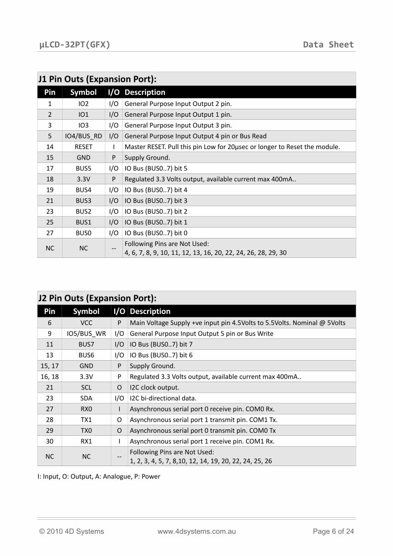
J1 Pin Outs (Expansion Port):Pin Symbol I/O Description
1 IO2 I/O General Purpose Input Output 2 pin.
2 IO1 I/O General Purpose Input Output 1 pin.
3 IO3 I/O General Purpose Input Output 3 pin.
5 IO4/BUS_RD I/O General Purpose Input Output 4 pin or Bus Read
14 RESET I Master RESET. Pull this pin Low for 20μsec or longer to Reset the module.
15 GND P Supply Ground.
17 BUS5 I/O IO Bus (BUS0..7) bit 5
18 3.3V P Regulated 3.3 Volts output, available current max 400mA..
19 BUS4 I/O IO Bus (BUS0..7) bit 4
21 BUS3 I/O IO Bus (BUS0..7) bit 3
23 BUS2 I/O IO Bus (BUS0..7) bit 2
25 BUS1 I/O IO Bus (BUS0..7) bit 1
27 BUS0 I/O IO Bus (BUS0..7) bit 0
NC NC --Following Pins are Not Used: 4, 6, 7, 8, 9, 10, 11, 12, 13, 16, 20, 22, 24, 26, 28, 29, 30
J2 Pin Outs (Expansion Port):Pin Symbol I/O Description
6 VCC P Main Voltage Supply +ve input pin 4.5Volts to 5.5Volts. Nominal @ 5Volts
9 IO5/BUS_WR I/O General Purpose Input Output 5 pin or Bus Write
11 BUS7 I/O IO Bus (BUS0..7) bit 7
13 BUS6 I/O IO Bus (BUS0..7) bit 6
15, 17 GND P Supply Ground.
16, 18 3.3V P Regulated 3.3 Volts output, available current max 400mA..
21 SCL O I2C clock output.
23 SDA I/O I2C bi-directional data.
27 RX0 I Asynchronous serial port 0 receive pin. COM0 Rx.
28 TX1 O Asynchronous serial port 1 transmit pin. COM1 Tx.
29 TX0 O Asynchronous serial port 0 transmit pin. COM0 Tx
30 RX1 I Asynchronous serial port 1 receive pin. COM1 Rx.
NC NC --Following Pins are Not Used: 1, 2, 3, 4, 5, 7, 8,10, 12, 14, 19, 20, 22, 24, 25, 26
I: Input, O: Output, A: Analogue, P: Power
© 2010 4D Systems www.4dsystems.com.au Page 6 of 24
µLCD-32PT(GFX) Data Sheet
2. Hardware Interface - Pins
The uLCD-32PT(GFX) provides both a hardware and a software interface. This section describes in detail the hardware interface pins of the device.
2.1 Serial Ports - COM0, COM1 UARTS
The PICASO-GFX2 has two dedicated hardware Asynchronous Serial ports that can communicate with external serial devices. These are referred to as the COM0 and the COM1 serial ports.
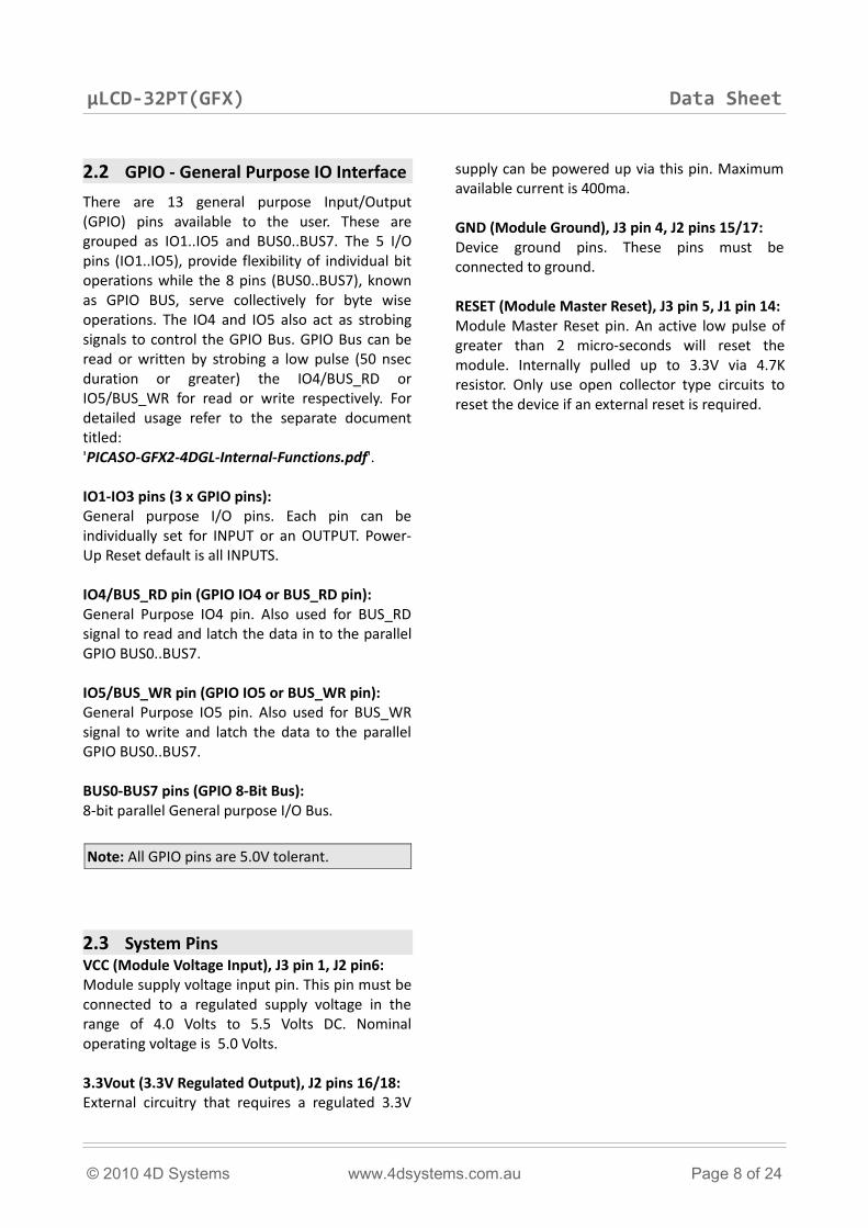
The primary features are:• Full-Duplex 8 bit data transmission and
reception.
• Data format: 8 bits, No Parity, 1 Stop bit.
• Independent Baud rates from 300 baud up to 256K baud.
• Single byte transmits and receives or a fully buffered service. The buffered service feature runs in the background capturing and buffering serial data without the user application having to constantly poll any of the serial ports. This frees up the application to service other tasks.
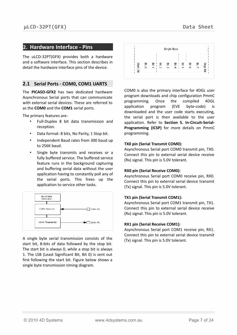
A single byte serial transmission consists of the start bit, 8-bits of data followed by the stop bit. The start bit is always 0, while a stop bit is always 1. The LSB (Least Significant Bit, Bit 0) is sent out first following the start bit. Figure below shows a single byte transmission timing diagram.
COM0 is also the primary interface for 4DGL user program downloads and chip configuration PmmC programming. Once the compiled 4DGL application program (EVE byte-code) is downloaded and the user code starts executing, the serial port is then available to the user application. Refer to Section 5. In-Circuit-Serial-Programming (ICSP) for more details on PmmC programming.
TX0 pin (Serial Transmit COM0):Asynchronous Serial port COM0 transmit pin, TX0. Connect this pin to external serial device receive (Rx) signal. This pin is 5.0V tolerant.
RX0 pin (Serial Receive COM0):Asynchronous Serial port COM0 receive pin, RX0. Connect this pin to external serial device transmit (Tx) signal. This pin is 5.0V tolerant.
TX1 pin (Serial Transmit COM1):Asynchronous Serial port COM1 transmit pin, TX1. Connect this pin to external serial device receive (Rx) signal. This pin is 5.0V tolerant.
RX1 pin (Serial Receive COM1):Asynchronous Serial port COM1 receive pin, RX1. Connect this pin to external serial device transmit (Tx) signal. This pin is 5.0V tolerant.
© 2010 4D Systems www.4dsystems.com.au Page 7 of 24
µLCD-32PT(GFX) Data Sheet
2.2 GPIO - General Purpose IO Interface
There are 13 general purpose Input/Output (GPIO) pins available to the user. These are grouped as IO1..IO5 and BUS0..BUS7. The 5 I/O pins (IO1..IO5), provide flexibility of individual bit operations while the 8 pins (BUS0..BUS7), known as GPIO BUS, serve collectively for byte wise operations. The IO4 and IO5 also act as strobing signals to control the GPIO Bus. GPIO Bus can be read or written by strobing a low pulse (50 nsec duration or greater) the IO4/BUS_RD or IO5/BUS_WR for read or write respectively. For detailed usage refer to the separate document titled: 'PICASO-GFX2-4DGL-Internal-Functions.pdf'.
IO1-IO3 pins (3 x GPIO pins):General purpose I/O pins. Each pin can be individually set for INPUT or an OUTPUT. Power-Up Reset default is all INPUTS.
IO4/BUS_RD pin (GPIO IO4 or BUS_RD pin):General Purpose IO4 pin. Also used for BUS_RD signal to read and latch the data in to the parallel GPIO BUS0..BUS7.
IO5/BUS_WR pin (GPIO IO5 or BUS_WR pin):General Purpose IO5 pin. Also used for BUS_WR signal to write and latch the data to the parallel GPIO BUS0..BUS7.
BUS0-BUS7 pins (GPIO 8-Bit Bus):8-bit parallel General purpose I/O Bus.
Note: All GPIO pins are 5.0V tolerant.
2.3 System PinsVCC (Module Voltage Input), J3 pin 1, J2 pin6:Module supply voltage input pin. This pin must be connected to a regulated supply voltage in the range of 4.0 Volts to 5.5 Volts DC. Nominal operating voltage is 5.0 Volts.
3.3Vout (3.3V Regulated Output), J2 pins 16/18:External circuitry that requires a regulated 3.3V
supply can be powered up via this pin. Maximum available current is 400ma.
GND (Module Ground), J3 pin 4, J2 pins 15/17:Device ground pins. These pins must be connected to ground.
RESET (Module Master Reset), J3 pin 5, J1 pin 14:Module Master Reset pin. An active low pulse of greater than 2 micro-seconds will reset the module. Internally pulled up to 3.3V via 4.7K resistor. Only use open collector type circuits to reset the device if an external reset is required.
© 2010 4D Systems www.4dsystems.com.au Page 8 of 24
µLCD-32PT(GFX) Data Sheet
3. Software Platform - 4DGL
The PICASO-GFX2 belongs to a family of processors powered by a highly optimised soft core virtual engine, E.V.E. (Extensible Virtual Engine).
EVE is a proprietary, high performance virtual processor with an extensive byte-code instruction set optimised to execute compiled 4DGL programs. 4DGL (4D Graphics Language) was specifically developed from ground up for the EVE engine core. It is a high level language which is easy to learn and simple to understand yet powerful enough to tackle many embedded graphics applications.
4DGL is a graphics oriented language allowing rapid application development and the syntax structure was designed using elements of popular languages such as C, Basic, Pascal and others. Programmers familiar with these languages will feel right at home with 4DGL. It includes many familiar instructions such as IF..ELSE..ENDIF, WHILE..WEND, REPEAT..UNTIL, GOSUB..ENDSUB, GOTO, PRINT as well as some specialised instructions SERIN, SEROUT, GFX_LINE, GFX_CIRCLE and many more. This section only covers the syntax of the available instructions and functions. For a more in depth study refer to the following documents:“4DGL-Programmers-Reference-Manual.pdf” “PICASO-GFX2-4DGL-Internal-Functions.pdf”
The following is a brief outline of 4DGL instructions and functions available for the PICASO-GFX2 device.
GPIO Functions:• pin_Set(mode, pin)
• OUTPUT, INPUT• pin_HI(pin)• pin_LO(pin)• pin_Read(pin)• bus_In()• bus_Out("var")• bus_Set("var")• bus_Write("var")• bus_Read("var")
System Memory Access Functions:• peekW(address)• pokeW(address, word_value)
Maths Functions:• ABS(value)• MIN(value1, value2)• MAX(value1, value2)• SWAP(&var1, &var2)• SIN(angle)• COS(angle)• RAND()• SEED(number)• SQRT(number)• OVF ()
Text and String Functions:• txt_MoveCursor(line, column)• putch(char)• putstr(pointer)• putnum(format, value)• print(...)• to(outstream)• charwidth('char')• charheight('char')• strwidth(pointer)• strheight()• strlen(pointer)• txt_Set(function, value)
txt_Set shortcuts:• txt_FGcolour(colour)• txt_BGcolour(colour)• txt_FontID(id)• txt_Width(multiplier)• txt_Height(multiplier)• txt_Xgap(pixelcount)• txt_Ygap(pixelcount)• txt_Delay(millisecs) [deprecated]• txt_Opacity(mode)• txt_Bold(mode)• txt_Italic(mode)• txt_Inverse(mode)• txt_Underlined(mode)• txt_Attributes(value)• txt_Wrap(value)
CType Functions:
© 2010 4D Systems www.4dsystems.com.au Page 9 of 24
µLCD-32PT(GFX) Data Sheet
• isdigit(char)• isxdigit(char)• isupper(char)• islower(char)• isalpha(char)• isalnum(char)• isprint(char)• isspace(char)• iswhite(char)• toupper(char)• tolower(char)• LObyte(var)• HIbyte(var)• ByteSwap(var)
Graphics Functions:• gfx_Cls()• gfx_ChangeColour(oldColour, newColour)• gfx_Circle(x, y, radius, colour)• gfx_CircleFilled(x, y, radius, colour)• gfx_Line(x1, y1, x2, y2, colour)• gfx_Hline(y, x1, x2, colour)• gfx_Vline(x, y1, y2, colour)• gfx_Rectangle(x1, y1, x2, y2, colour)• gfx_RectangleFilled(x1, y1, x2, y2, colour)• gfx_Polyline(n, vx, vy, colour)• gfx_Polygon(n, vx, vy, colour)• gfx_Triangle(x1, y1, x2, y2, x3, y3, colour)• gfx_Dot()• gfx_Bullet(radius)• gfx_OrbitInit(&x_dest, &y_dest)• gfx_Orbit(angle, distance)• gfx_PutPixel(x, y, colour)• gfx_GetPixel(x, y)• gfx_MoveTo(xpos, ypos)• gfx_MoveRel(xoffset, yoffset)• gfx_IncX()• gfx_IncY()• gfx_LineTo(xpos, ypos)• gfx_LineRel(xpos, ypos)• gfx_BoxTo(x2, y2)• gfx_SetClipRegion()• gfx_Ellipse(x, y, xrad, yrad, colour)• gfx_EllipseFilled(x, y, xrad, yrad, colour)• gfx_Button(state, x, y, buttonColour,
textColour, font, textWidth, textHeight,
text)• gfx_Panel(state, x, y, width, height, colour)• gfx_Slider(mode, x1, y1, x2, y2, colour,
scale, value)• gfx_ScreenCopyPaste(xs, ys, xd, yd, width,
height)• gfx_RGBto565(RED, GREEN, BLUE)• gfx_332to565(COLOUR8BIT)• gfx_Selection(index, backcolor, textcolor)• gfx_TriangleFilled(x1, y1, x2, y2, x3, y3,
colr)• gfx_PolygonFilled(n, &vx, &vy, colr)• gfx_Origin(x, y)• gfx_Get(mode)• gfx_ClipWindow(x1, y1, x2, y2)• gfx_Set(function, value)
gfx_Set shortcuts:• gfx_PenSize(mode)• gfx_BGcolour(colour)• gfx_ObjectColour(colour)• gfx_Clipping(mode)• gfx_TransparentColour(colour)
not implemented• gfx_Transparency(mode)
not implemented• gfx_FrameDelay(delay)• gfx_ScreenMode(delay)• gfx_OutlineColour(colour)• gfx_Contrast(value)• gfx_LinePattern(pattern)• gfx_ColourMode(mode)• gfx_BevelWidth(mode)• gfx_BevelShadow(value)• gfx_Xorigin(offset)• gfx_Yorigin(offset)
Display I/O Functions:• disp_SetReg(register, data)• disp_setGRAM(x1, y1, x2, y2)• disp_WrGRAM(colour)• disp_WriteControl(value)• disp_WriteWord(value)• disp_ReadWord()
Media Functions (SD/SDHC memory Card or Serial Flash chip):
• media_Init()
© 2010 4D Systems www.4dsystems.com.au Page 10 of 24
µLCD-32PT(GFX) Data Sheet
• media_SetAdd(HIword, LOword)• media_SetSector(HIword, LOword)• media_RdSector(Destination_Address)• media_WrSector(Source_Address)• media_ReadByte()• media_ReadWord()• media_WriteByte(byte_val)• media_WriteWord(word_val)• media_Flush()• media_Image(x, y)• media_Video(x, y)• media_VideoFrame(x, y, frameNumber)
Flash Memory chip Functions:• flash_SIG()• flash_ID()• flash_BulkErase()• flash_BlockErase(blockAddress)
SPI Control Functions:• spi_Init(speed,input_mode,output_mode)• spi_Read()• spi_Write(byte)• spi_Disable()
Serial (UART) Communications Functions:• setbaud(rate)• com_SetBaud(comport, baudrate/10)• serin() or serin1()• serout(char) or serout1(char)• com_Init(buffer, buffsize, qualifier) or
com1_Init(buffer, buffsize, qualifier) • com_Reset() or com1_Reset() • com_Count() or com1_Count() • com_Full() or com1_Full() • com_Error() or com1_Error() • com_Sync() or com1_Sync() • com_TXbuffer(buf, bufsize) or
com1_TXbuffer(buf, bufsize)• com_TXcount() or com1_TXcount()• com_TXemptyEvent(function) or
com1_TXemptyEvent(function)
I2C BUS Master Function• func I2C_Open(Speed)• func I2C_Close()• func I2C_Start()• func I2C_Stop()
• func I2C_Restart()• func I2C_Read()• func I2C_Write(byte)• func I2C_Ack()• func I2C_Nack()• func I2C_AckStatus()• func I2C_AckPoll(control)• func I2C_Idle()• func I2C_Gets(buffer, size)• func I2C_Getn(buffer, size)• func I2C_Puts(buffer)• func I2C_Putn(buffer,count)
Timer Functions:• sys_T()• sys_T_HI()• sys_SetTimer(timernum, value)• sys_GetTimer(timernum)• sys_SetTimerEvent("timernum","functin")• sys_EventQueue()• sys_EventsPostpone()• sys_EventsResume()• sys_Sleep(units)• iterator(offset)
FAT16 File Functions:• file_Error()• file_Count(filename)• file_Dir(filename)• file_FindFirst(fname)• file_FindNext()• file_Exists(fname)• file_Open(fname, mode)• file_Close(handle)• file_Read(destination, size, handle)• file_Seek(handle, HiWord, LoWord)• file_Index(handle,Hisize,Losize,recrdnum)• file_Tell(handle, &HiWord, &LoWord)• file_Write(Source, size, handle)• file_Size(handle, &HiWord, &LoWord)• file_Image(x, y, handle)• file_ScreenCapture(x, y, width, height,
handle)• file_PutC(char, handle)• file_GetC(handle)• file_PutW(word, handle)• file_GetW(handle)
© 2010 4D Systems www.4dsystems.com.au Page 11 of 24
µLCD-32PT(GFX) Data Sheet
• file_PutS(source, handle)• file_GetS(*String, size, handle)• file_Erase(fname)• file_Rewind(handle)• file_LoadFunction(fname.4XE)• file_Run(fname..4XE, arglistptr)• file_Exec(fname..4XE, arglistptr)• file_LoadImageControl(fname1, fname2,
mode)• file_Mount()• file_Unmount()• file_PlayWAV
Sound Control Functions:• Snd_Volume(var)• Snd_Pitch(pitch)• Snd_BufSize(var)• Snd_Stop()• Snd_Pause()• Snd_Continue()• Snd_Playing()
String Class Functions:• str_Ptr(&var)• str_GetD(&ptr, &var)• str_GetW(&ptr, &var)• str_GetHexW(&ptr, &var)• str_GetC(&ptr, &var)• str_GetByte(ptr)• str_GetWord(ptr)• str_PutByte(ptr, val)• str_PutWord(ptr, val)• str_Match(&ptr, *str)• str_MatchI(&ptr, *str)• str_Find(&ptr, *str)• str_FindI(&ptr, *str)• str_Length(ptr)• str_Printf(&ptr, *format)• str_Cat(&destination, &Source)• str_CatN(&ptr, str, count)
Touch Screen Functions:• touch_DetectRegion(x1, y1, x2, y2)• touch_Set(mode)• touch_Get(mode)
Image Control Functions:• img_SetPosition(handle, index, xpos, ypos)
• img_Enable(handle, index)• img_Disable(handle, index)• img_Darken(handle, index)• img_Lighten(handle, index)• img_SetWord(handle, index, offset, word)• img_GetWord(handle, index, offset)• img_Show(handle, index)• img_SetAttributes(handle, index, value)• img_ClearAttributes(handle, index, value)• img_Touched(handle, index)
Memory Allocation Functions:• mem_Alloc(size)• mem_Allocv(size)• mem_Allocz(size)• mem_Realloc(ptr, size)• mem_Free(allocation)• mem_Heap()• mem_Set(ptr, char, size)• mem_Copy(source, destination, count)• mem_Compare(ptr1, ptr2, count)
General Purpose Functions:• pause(time)• lookup8 (key, byteConstList )• lookup16 (key, wordConstList )
To assist with the development of 4DGL applications, the 4DGL-Workshop3 IDE combines a full-featured editor, a compiler, a linker and a down-loader into a single PC-based application. It's all you need to code, test and run your applications. C
© 2010 4D Systems www.4dsystems.com.au Page 12 of 24
µLCD-32PT(GFX) Data Sheet
4. PmmC Programming
The PICASO-GFX2, used in the uLCD-32PT(GFX) module, is a custom graphics controller. All functionality including the high level commands are built into the chip. This chip level configuration is available as a PmmC (Personality-module-micro-Code) file.
A PmmC file contains all of the low level micro-code information (analogy of that of a soft silicon) which define the characteristics and functionality of the device. The ability of programming the device with a PmmC file provides an extremely flexible method of customising as well as upgrading it with future enhancements.
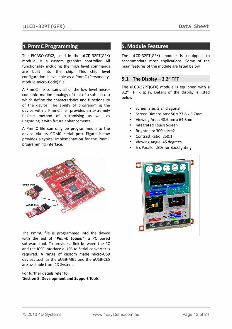
A PmmC file can only be programmed into the device via its COM0 serial port Figure below provides a typical implementation for the PmmC programming interface.
The PmmC file is programmed into the device with the aid of “PmmC Loader”, a PC based software tool. To provide a link between the PC and the ICSP interface a USB to Serial converter is required. A range of custom made micro-USB devices such as the uUSB-MB5 and the uUSB-CE5 are available from 4D Systems.
For further details refer to:'Section 8: Development and Support Tools'.
5. Module Features
The uLCD-32PT(GFX) module is equipped to accommodate most applications. Some of the main features of the module are listed below.
5.1 The Display – 3.2” TFT
The uLCD-32PT(GFX) module is equipped with a 3.2” TFT display. Details of the display is listed below:
• Screen Size: 3.2” diagonal• Screen Dimensions: 56 x 77.6 x 3.7mm• Viewing Area: 48.6mm x 64.8mm• Integrated Touch Screen• Brightness: 300 cd/m2 • Contrast Ratio: 250:1• Viewing Angle: 45 degrees • 5 x Parallel LEDs for Backlighting
© 2010 4D Systems www.4dsystems.com.au Page 13 of 24
µLCD-32PT(GFX) Data Sheet
5.2 The PICASO-GFX2 Processor
The module is designed around the PICASO-GFX2 Graphics Controller from 4D-Labs.
The PICASO-GFX2 is a smart Controller and the interface to the TFT- LCD displays is almost plug-n-play. All of the data and control signals are provided by the chip to interface directly to the display.
Powerful graphics, text, image, animation and countless more features are built right inside the chip. It offers a simple yet effective serial interface to any external micro-controller that can communicate via a serial port.
The data sheet for the chip is available from the www.4dsystems.com.au website:“PICASO-GFX2-DS-revx.pdf”
5.3 The uSD Memory Card
The module supports micro-SD memory cards via the on-board uSD connector. The memory card is used for all multimedia file retrieval such as images, animations and movie clips. The memory card can also be used as general purpose storage for data logging applications. Support is available for off the shelf micro-SD and high capacity HC memory cards (4Gb and above).
Note: The module also supports FAT file formats.
5.4 The Audio
The exclusive audio support in the PICASO-GFX2 makes it better than its peers in the Graphics processor range. PWM ensures better sound quality with a volume range of 8 to 127. A simple instruction empowers the user to execute the audio files. Audio operation can be carried out simultaneously with the execution of other necessary instructions.
For a complete list of audio commands please refer to the separate document titled 'PICASO-GFX2-4DGL-Internal-Functions.pdf'..
Note: The on-board speaker is a small surface mount device and is designed to project into an audio cavity. It is not very loud by itself..
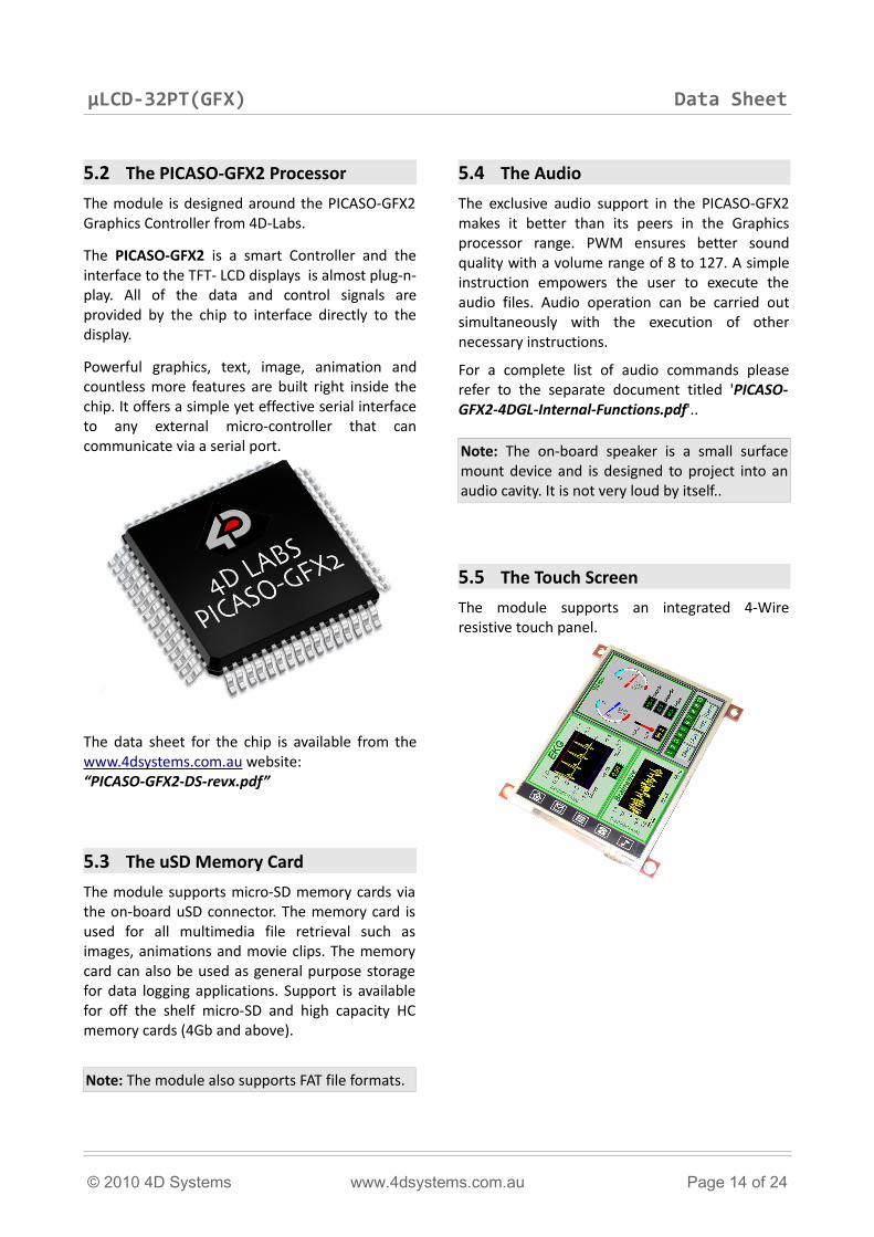
5.5 The Touch Screen
The module supports an integrated 4-Wire resistive touch panel.
© 2010 4D Systems www.4dsystems.com.au Page 14 of 24
µLCD-32PT(GFX) Data Sheet
6. Memory Cards – FAT16 Format
The PICASO-GFX2 uses off the shelf standard SDHC/SD/microSD memory cards with up to 2Gb capacity usable with FAT16 formatting. For any FAT file related operations, before the memory card can be used it must first be formatted with FAT16 option. The formatting of the card can be done on any PC system with a card reader. Select the appropriate drive and choose the FAT16 (or just FAT in some systems) option when formatting. The card is now ready to be used in the PICASO-GFX2 based application.
The PICASO-GFX2 also supports high capacity HC memory cards (4Gb and above). The available capacity of SD-HC cards varies according to the way the card is partitioned and the commands used to access it.
The FAT partition is always first (if it exists) and can be up to the maximum size permitted by FAT16. Windows will format FAT16 up to 2Gb and the Windows command prompt will format FAT16 up to 4Gb.
For the RAW partition, byte reads and writes can access 2^32 (i.e. 4gb) of the card, Sector reads and writes can access 2^24 sectors (of 512 bytes, i.e. 8gb).
The total amount of the card usable is the sum of the FAT and RAW partitions.
7. Display Precautions• Avoid having to display the same image/object
on the screen for lengthy periods of time. This will cause a burn-in which is a common problem with all types of display technologies. Blank the screen after a while or dim it very low by adjusting the contrast. Better still; implement a screen saver feature.
• Moisture and water can damage the display. Moisture on the surface of a powered display will cause the electrodes to corrode. Wipe off any moisture gently or let the display dry before usage.
• Dirt from fingerprint oil and fat can easily stain the surface of the display. Gently wipe off any stains with a soft lint-free cloth.
• The performance of the display will degrade under high temperature and humidity. Avoid such conditions when storing.
• Do not tamper with the display flex cable that is connected to the control board. This may effect the connection between the display and the driving circuitry and cause failure.
• Displays are susceptible to mechanical shock and any force exerted on the module may result in deformed zebra strips, a cracked display cell and broken backlight
• Always use the mounting holes on the module's printed circuit board to mount the display.
© 2010 4D Systems www.4dsystems.com.au Page 15 of 24
µLCD-32PT(GFX) Data Sheet
8. Development and Support Tools
8.1 PmmC Loader – PmmC Programming Software Tool
The ‘PmmC Loader’ is a free software tool for Windows based PC platforms. Use this tool to program the latest PmmC file into the PICASO-GFX2 chip embedded in the uLCD-32PT(GFX) module. It is available for download from the 4D Systems website, www.4dsystems.com.au
8.2 microUSB – PmmC Programming Hardware Tool
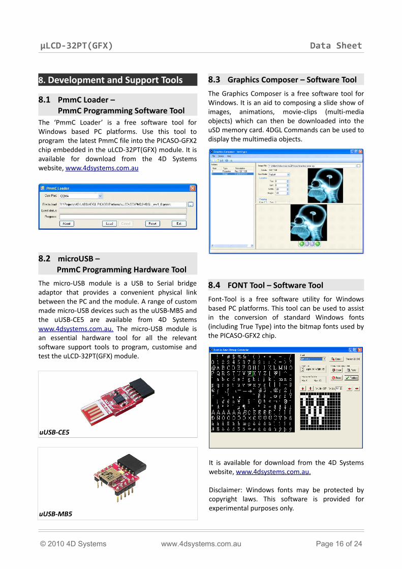
The micro-USB module is a USB to Serial bridge adaptor that provides a convenient physical link between the PC and the module. A range of custom made micro-USB devices such as the uUSB-MB5 and the uUSB-CE5 are available from 4D Systems www.4dsystems.com.au. The micro-USB module is an essential hardware tool for all the relevant software support tools to program, customise and test the uLCD-32PT(GFX) module.
8.3 Graphics Composer – Software Tool
The Graphics Composer is a free software tool for Windows. It is an aid to composing a slide show of images, animations, movie-clips (multi-media objects) which can then be downloaded into the uSD memory card. 4DGL Commands can be used to display the multimedia objects.
8.4 FONT Tool – Software Tool
Font-Tool is a free software utility for Windows based PC platforms. This tool can be used to assist in the conversion of standard Windows fonts (including True Type) into the bitmap fonts used by the PICASO-GFX2 chip.
It is available for download from the 4D Systems website, www.4dsystems.com.au .
Disclaimer: Windows fonts may be protected by copyright laws. This software is provided for experimental purposes only.
© 2010 4D Systems www.4dsystems.com.au Page 16 of 24
uUSB-MB5
uUSB-CE5
µLCD-32PT(GFX) Data Sheet
8.5 RMPET – Software Tool
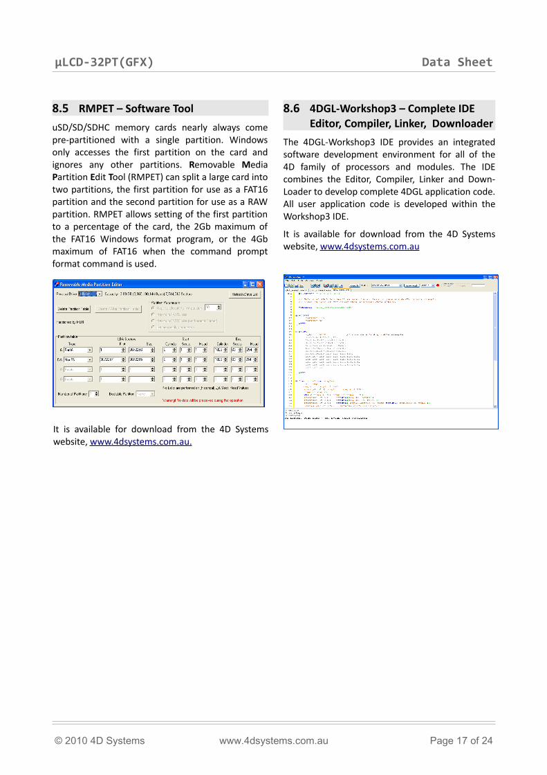
uSD/SD/SDHC memory cards nearly always come pre-partitioned with a single partition. Windows only accesses the first partition on the card and ignores any other partitions. Removable Media Partition Edit Tool (RMPET) can split a large card into two partitions, the first partition for use as a FAT16 partition and the second partition for use as a RAW partition. RMPET allows setting of the first partition to a percentage of the card, the 2Gb maximum of the FAT16 Windows format program, or the 4Gb maximum of FAT16 when the command prompt format command is used.
It is available for download from the 4D Systems website, www.4dsystems.com.au .
8.6 4DGL-Workshop3 – Complete IDE Editor, Compiler, Linker, Downloader
The 4DGL-Workshop3 IDE provides an integrated software development environment for all of the 4D family of processors and modules. The IDE combines the Editor, Compiler, Linker and Down-Loader to develop complete 4DGL application code. All user application code is developed within the Workshop3 IDE.
It is available for download from the 4D Systems website, www.4dsystems.com.au
© 2010 4D Systems www.4dsystems.com.au Page 17 of 24
µLCD-32PT(GFX) Data Sheet
8.7 Expansion Board : P1-EB
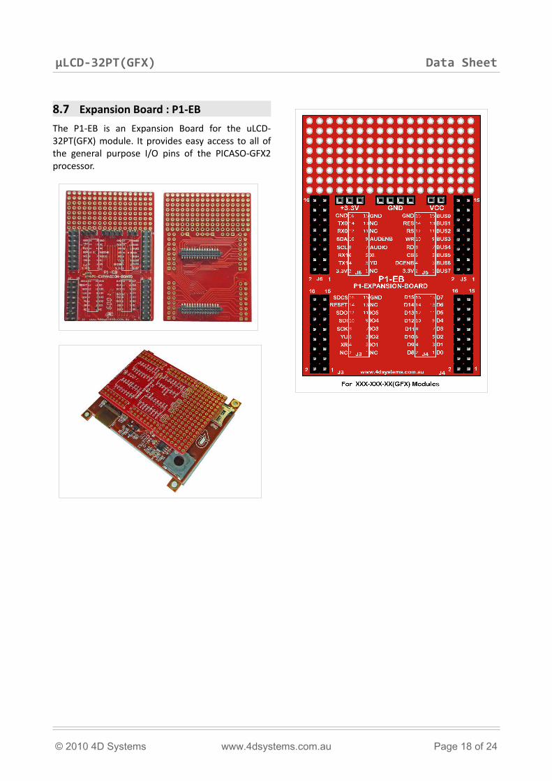
The P1-EB is an Expansion Board for the uLCD-32PT(GFX) module. It provides easy access to all of the general purpose I/O pins of the PICASO-GFX2 processor.
© 2010 4D Systems www.4dsystems.com.au Page 18 of 24
µLCD-32PT(GFX) Data Sheet
9. Mechanical Details
© 2010 4D Systems www.4dsystems.com.au Page 19 of 24
µLCD-32PT(GFX) Data Sheet
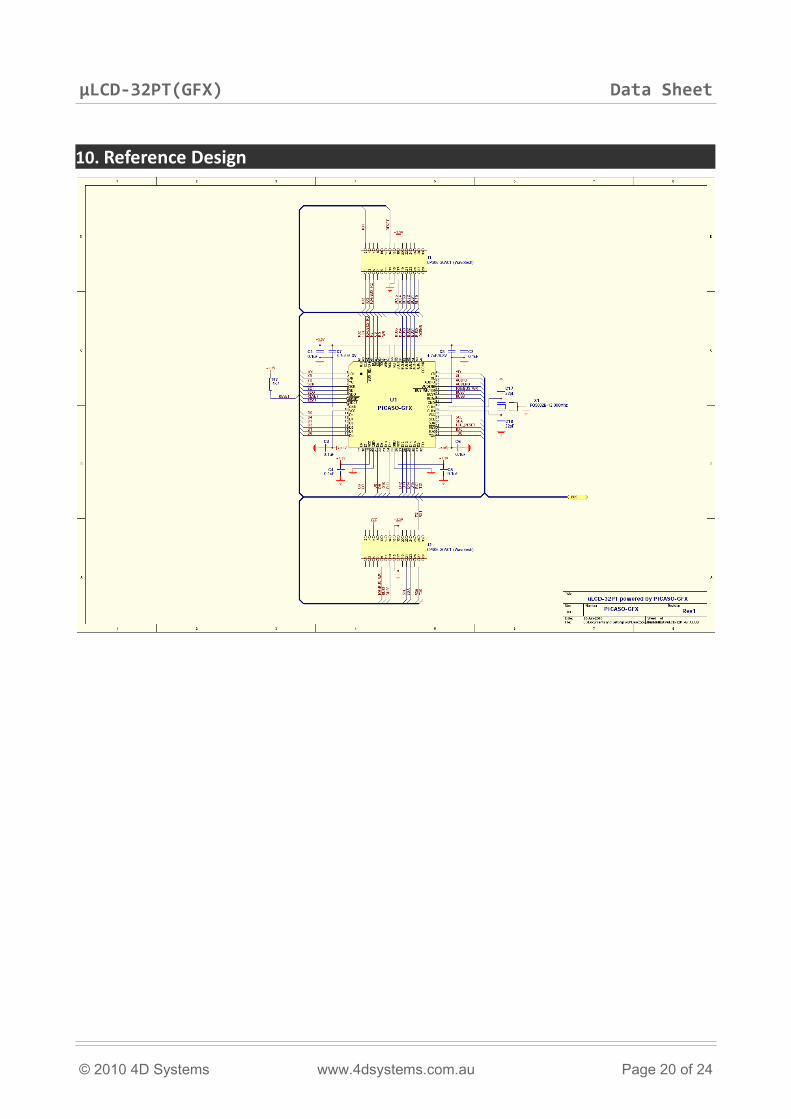
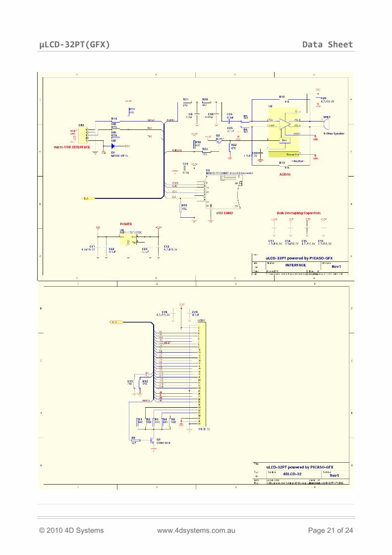
10. Reference Design
© 2010 4D Systems www.4dsystems.com.au Page 20 of 24
µLCD-32PT(GFX) Data Sheet
© 2010 4D Systems www.4dsystems.com.au Page 21 of 24
µLCD-32PT(GFX) Data Sheet
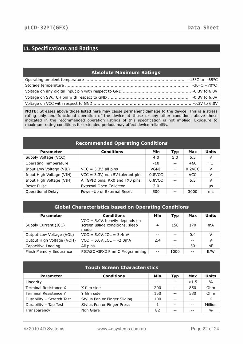
11. Specifications and Ratings
Absolute Maximum Ratings
Operating ambient temperature .......................................................................... -15°C to +65°C
Storage temperature ............................................................................................. -30°C +70°C
Voltage on any digital input pin with respect to GND ................................................... -0.3V to 6.0V
Voltage on SWITCH pin with respect to GND ............................................................ -0.3V to 6.0V
Voltage on VCC with respect to GND ......................................................................... -0.3V to 6.0V
NOTE: Stresses above those listed here may cause permanent damage to the device. This is a stress rating only and functional operation of the device at those or any other conditions above those indicated in the recommended operation listings of this specification is not implied. Exposure to maximum rating conditions for extended periods may affect device reliability.
Recommended Operating Conditions
Parameter Conditions Min Typ Max Units
Supply Voltage (VCC) 4.0 5.0 5.5 V
Operating Temperature -10 -- +60 °C
Input Low Voltage (VIL) VCC = 3.3V, all pins VGND -- 0.2VCC V
Input High Voltage (VIH) VCC = 3.3V, non 5V tolerant pins 0.8VCC -- VCC V
Input High Voltage (VIH) All GPIO pins, RX0 and TX0 pins 0.8VCC -- 5.5 V
Reset Pulse External Open Collector 2.0 -- -- µs
Operational Delay Power-Up or External Reset 500 -- 3000 ms
Global Characteristics based on Operating Conditions
Parameter Conditions Min Typ Max Units
Supply Current (ICC)VCC = 5.0V, heavily depends on screen usage conditions, sleep mode
4 150 170 mA
Output Low Voltage (VOL) VCC = 5.0V, IOL = 3.4mA -- -- 0.4 V
Output High Voltage (VOH) VCC = 5.0V, IOL = -2.0mA 2.4 -- -- V
Capacitive Loading All pins -- -- 50 pF
Flash Memory Endurance PICASO-GFX2 PmmC Programming -- 1000 -- E/W
Touch Screen Characteristics
Parameter Conditions Min Typ Max Units
Linearity -- -- <1.5 %
Terminal Resistance X X film side 200 -- 850 Ohm
Terminal Resistance Y Y film side 150 -- 580 Ohm
Durability – Scratch Test Stylus Pen or Finger Sliding 100 -- -- K
Durability – Tap Test Stylus Pen or Finger Press 1 -- -- Million
Transparency Non Glare 82 -- -- %
© 2010 4D Systems www.4dsystems.com.au Page 22 of 24
µLCD-32PT(GFX) Data Sheet
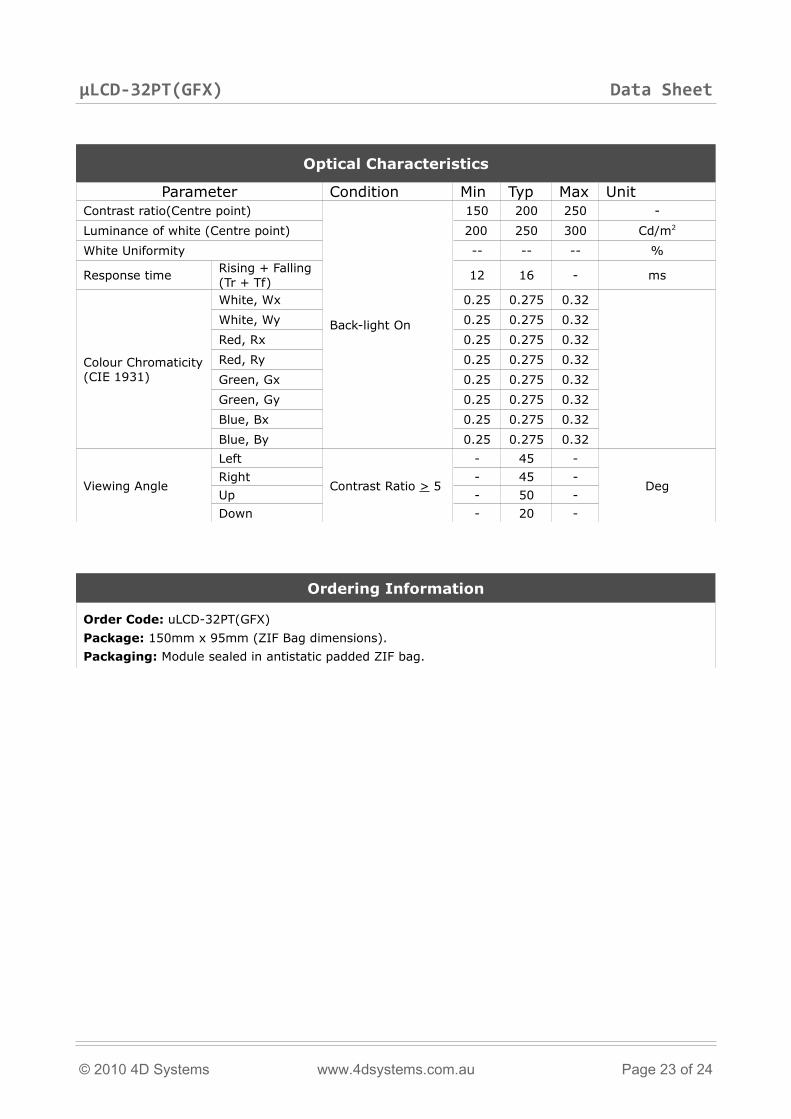
Optical Characteristics
Parameter Condition Min Typ Max UnitContrast ratio(Centre point)
Back-light On
150 200 250 -
Luminance of white (Centre point) 200 250 300 Cd/m2
White Uniformity -- -- -- %
Response timeRising + Falling(Tr + Tf)
12 16 - ms
Colour Chromaticity(CIE 1931)
White, Wx 0.25 0.275 0.32
White, Wy 0.25 0.275 0.32
Red, Rx 0.25 0.275 0.32
Red, Ry 0.25 0.275 0.32
Green, Gx 0.25 0.275 0.32
Green, Gy 0.25 0.275 0.32
Blue, Bx 0.25 0.275 0.32
Blue, By 0.25 0.275 0.32
Viewing Angle
Left
Contrast Ratio > 5
- 45 -
DegRight - 45 -
Up - 50 -
Down - 20 -
Ordering Information
Order Code: uLCD-32PT(GFX)
Package: 150mm x 95mm (ZIF Bag dimensions).
Packaging: Module sealed in antistatic padded ZIF bag.
© 2010 4D Systems www.4dsystems.com.au Page 23 of 24
µLCD-32PT(GFX) Data Sheet
Proprietary Information
The information contained in this document is the property of 4D Systems Pty. Ltd. and may be the subject of patents pending or granted, and must not be copied or disclosed with out prior written permission.
4D Systems endeavours to ensure that the information in this document is correct and fairly stated but does not accept liability for any error or omission. The development of 4D Systems products and services is continuous and published information may not be up to date. It is important to check the current position with 4D Systems.
All trademarks belong to their respective owners and are recognised and acknowledged.
Disclaimer of Warranties & Limitation of Liability
4D Systems makes no warranty, either express or implied with respect to any product, and specifically disclaims all other warranties, including, without limitation, warranties for merchantability, non-infringement and fitness for any particular purpose.
Information contained in this publication regarding device applications and the like is provided only for your convenience and may be superseded by updates. It is your responsibility to ensure that your application meets with your specifications.
In no event shall 4D Systems be liable to the buyer or to any third party for any indirect, incidental, special, consequential, punitive or exemplary damages (including without limitation lost profits, lost savings, or loss of business opportunity) arising out of or relating to any product or service provided or to be provided by 4D Systems, or the use or inability to use the same, even if 4D Systems has been advised of the possibility of such damages.
Use of 4D Systems’ devices in life support and/or safety applications is entirely at the buyer’s risk, and the buyer agrees to defend, indemnify and hold harmless 4D Systems from any and all damages, claims, suits, or expenses resulting from such use. No licenses are conveyed, implicitly or otherwise, under any 4D Systems intellectual property rights.
Contact Information
For Technical Support : [email protected]
For Sales Support : [email protected]
Website : www.4dsystems.com.au
Copyright 4D Systems Pty. Ltd. 2000-2010.
© 2010 4D Systems www.4dsystems.com.au Page 24 of 24