Embed Size (px)
Citation preview

LC Product Specification 640-252-056 D02AK0036 Issue 3 January 27, 2006

LC Product Specification 640-252-056
LC Product Specification General Definition: The LC Connector Product is a robust optical connector designed to support Telecom and Datacom networks. The connector family includes but not limited to jumper connectors, Behind-the-Wall connectors (BTW), adapters, attenuators, modular adapters, device receptacles, jumpers, an assortment of connector modules and panels, and installation tool kits and consumable kits. The connector is defined as a small form factor connector (SFFC) with significant size reduction relative to traditional connectors, typically 50% smaller than standard SC and ST®fiber products. The square connector housing uses unique trigger and latch structures and a tunable cylindrical ferrule. The LC Connector family was designed to provide a high performance SFFC incorporating traditional technology, advances in latching systems, and versatile for both singlemode and multimode fiber applications. Terms of Specification: The specification document is intended to provide users of OFS LC Connector products a level of confidence and means of understanding the characteristics of purchased product. The product is designed and should be manufactured according to the specification document. The product specification serves as a guideline to the features and performance of the product, and is subject to change without notice. Definition of Products: LC Jumper Connectors: Robust family of connectors designed to mount on 1.6 mm fiber cordage and intended to meet the Telcordia GR-326-CORE, Issue 3, for Type I Media (typically 3.0mm cordage). Note: Telcordia GR-326-CORE, Issue 3 exceptions for smaller size and future changes for SFF connectors. LC BTW Connectors: Shorter LC connectors designed for 900 micron buffered fiber. This product is intended to meet Telcordia GR-326-CORE, Issue 3 for Type II Media (900 micron buffered fiber). LC Jumpers: Connectorized 1.6mm cordage in various lengths and fiber counts. Jumpers are produced in a vast array of hybrid configurations allowing interconnection between LC based product and other connector styles. These products are intended to meet Telcordia GR-326-CORE, Issue 3 for Type I Media. LC Adapters: Two port configuration for joining two LC connectors. The adapter contains the alignment sleeve for the precise alignment of the connector ferrules. Available in simplex, duplex and higher density configurations based on application needs. See also 0dB Modular Adapters. LC Attenuators & Modular Adapters: Attenuator products are configured as a Build-On style or a Modular Adapter. Build-On Attenuators are one-piece designs that combine an LC Connector and adapter and are available in several attenuation values. The Modular Adapters are Customer assembled from two separate single port adapters, a base and a cap. The cap is available in 0-dB and attenuated values. Each attenuator product reduces optical power internally. LC Device Receptacles: Device ports provide a mechanism for interfacing connectors to electronic subpackages (typically T.O. Cans). LC device receptacles are available in simplex and duplex configurations. Product Identification: LC products are easy to identify in accordance with industry standards: Blue represents singlemode Beige represents multimode Green represents singlemode APC (Angled End Face) A & B port identification is on duplex adapters in accordance with TIA 568 * ST® is a registered trademark of OFS, Inc.
LC Connector Product Specification Issue 4 January 2006
LC Product Specification 640-252-056
Table of Contents 1.0 LC Connector Specification……………………………….……....…….. 1 1.1 LC Connector Application……………………………………….…. 2 1.2 LC Jumper and BTW Connectors (Exploded View)………….….. 2 1.3 LC Connector Footprint Dimensions…………………………....… 3 1.4 LC Connector Materials………………………………………….…. 3 1.5a LC Simplex Connector Illustrations…………………..…..…...…. 4 1.5b LC Duplex Connector Illustration…………………..…..…...….... 5 1.5c LC Connector Specifications for Intermateability…………...….. 5 1.6 LC Zirconia Ferrule Surface Finish Specification …...….…...….. 7 1.7 LC Connector Ferrule Extension and Contact Force…………… 8 1.8 LC Reference Dimensions for Polishing Machine Fixtures…….. 8 1.9 LC Connector Coding ………………..……………………….……. 9 1.10 LC Connector Color Coding ………..………...…………….……. 9 2.0 LC Adapter Specification.…………………………………………….….. 10
2.1 LC Duplex and Simplex Adapters (Perspective View)……...…… 11 2.2 LC Adapter Footprint Dimensions……..……………………...…… 11 2.3 Panel Cutout Dimensions for Mounting LC Adapters…….…...… 12 2.4 LC Adapter Materials………………………..……………………… 12 2.5a LC Simplex Adapter Illustrations………..…….……………….…. 13 2.5b LC Duplex Adapter Illustration…………………………….……… 14 2.5c LC Adapter Specifications for Intermateability……………..…… 14 2.6 LC Duplex Adapter Mounting Options……………….....………… 16
2.7 LC Adapter Coding …………………………………………….…… 16 2.8 LC Adapter Color Coding…..………………….…………………… 16 3.0 LC Device Receptacle Specification…………………………………… 17
3.1 LC Simplex Device Receptacle (Front & Rear Exploded View)... 18 3.2 LC Duplex Device Receptacle (Front & Rear Exploded View)…. 19 3.3 LC Device Receptacle Materials……………………..………….… 20 3.4a LC Simplex Device Receptacle Illustrations……………………. 20 3.4b LC Duplex Device Receptacle Illustration………………………. 21 3.4c LC Device Receptacle Specifications for Intermateability…….. 21
3.5 LC Device Receptacle Interface – Alignment Sleeve Grade…... 22 3.6 Pin Gauge for LC Device Receptacle……………………..……… 23 3.7 Pin Gauge Grade Table………………………………….……….… 23
3.8 LC Device Receptacle Coding …...……………………………….. 23 3.9 LC Adapter Color Coding……………………….………………….. 23
LC Product Specification i Issue 4 January 2006
LC Product Specification 640-252-056
4.0 LC Attenuator Specification……………………………….……..……… 24 4.1 LC Attenuator Buildout System (Exploded View)….…………….. 25 4.2 LC Attenuator Buildout Footprint Dimensions…..……………….. 25 4.3 LC Attenuator Materials and Specifications……………………… 26 4.4 LC Attenuator Attenuation Levels and Performance….………… 27
4.5 LC Attenuator Compliance to GR-910-CORE……………………. 28 4.6 Spectral Flatness……………………………………………………. 29 4.7 Power Divergence…………………………………………………… 29
4.8 LC Attenuator Coding ……………………………….…………..…. 30 4.9 LC Attenuator Color Coding …………….………………..……….. 30 5.0 LC Jumper Specification…………………………….….……………….. 31 5.1 LC Simplex Jumper on 1.6mm cordage………….……………….. 32 5.2 LC Simplex Jumper Exploded Assembly…………….…..……….. 32 5.3 LC Duplex Jumper Exploded Assembly…………….…………….. 33 5.4 LC Duplex Jumper as per TIA/EIA...…………….………………… 33 5.5 LC Jumper/Connector Materials………………….……………….. 34
5.6 LC Minicord Technical Specifications……………..……………… 34 5.7 LC SM Ferrule Endface Geometry……….…….…………………. 35
5.8 LC APC Endface Geometry………………….…………………….. 36 5.9 LC APC Ferrule/Angle Orientation…………..……………………. 37 5.10 LC Factory Made Patch Cord Specifications…………………… 37 5.11 Visual Inspection Criteria for Fiber Optic Connectors…….…… 38 5.12 LC SM Jumper Tuning Configuration………………………….… 39 5.13 LC SM Jumper Laboratory Performance (Tuned vs. Untuned) 40 5.14 LC Jumpers – Available Configurations…………………………. 41 5.15 LC Jumper Coding ……………………..……………………….… 42 5.16 LC Jumper Color Coding ………………...………………………. 42 6.0 LC Connector Product Data………………………………………….…. 43 6.1 Performance Criteria (1997)…………………………………..…… 44 6.2 1997 Test Descriptions…………………………………….……….. 45-47 6.3 LC Test Results………………………………….…………...…...… 48 6.4 Test Data……….…………………………………………………..… 49-51
LC Product Specification ii Issue 4 January 2006
LC Product Specification 640-252-056
1.0 LC Connector Specification
LC Product Specification 1 Issue 4 January 2006

LC Product Specification 640-252-056
1.0 - LC Connector Specification
1.1 - LC Connector Application
LC DuplexJumper Connector LC BTW
Connectors
LC Duplex Adapter
LC Simplex Jumper ComponentsFOCIS 10 Designation d=0 n=1
ConnectorConnectors
Cable SupportCable Supports
Crimp SleeveAssembly
Duplex YokeMM Only
LC Duplex Jumper ComponentsFOCIS 10 Designation d=2 n=2
Crimp SleeveAssemblies
1.2a - LC Jumper Connectors: Exploded View
BTW Connector
Buffer Adapter
1.2b - LC BTW (Behind the Wall) Connector: Exploded View
LC Product Specification 2 Issue 4 January 2006

LC Product Specification 640-252-056
C F
E
DB
A
BTW Connector Jumper Connector
1.3 - LC Connector Footprint Dimensions
REF. DIMENSIONS
Minimum mm Maximum A - 30 B - 32 C 0.7 1.4 D - 49 E - 51 F 1.8 3.4
1.4 - LC Connector Materials
Connector Part Material UL 94 Rating Oxygen Index
Connector Housing Engineering Plastic V-0 50 Extender Cap Engineering Plastic V-0 50 Cable Support Thermoplastic Rubber H.B 23 Heat Shrink Tubing Polyolefin UL/CSA Recognized T.B.D. Buffer Adapter PVC V-0 29 Duplex Yoke Nylon H.B. 24 Spring Metal - - Ferrule Zirconia - - Crimp Sleeve Metal - - Jumper Ext. Cap Insert Metal - - Metal Barrel Metal/Teflon™ - - Plastic Barrel Engineering Plastic V-0 50
* Teflon is a registered trademark of Dupont
LC Product Specification 3 Issue 4 January 2006

LC Product Specification 640-252-056
B
MECHANICALREFERENCE
PLANE
OPTICALREFERENCE
PLANE
A
ACAB
O AA
Q R
Z
U
P S
W X
T
AD
MECHANICALREFERENCE
PLANE
b
b
V
C
D E
- B -
⊕ 0.05 BM
⊕ 0.05 BMa
a
M
N
I
YG
OPTICALREFERENCE
PLANE
⊕ 0.025 BA
M
J
H2
F- A -
L H1
Section b-bSection a-a
1.5a – LC Simplex Connector Illustrations
LC Product Specification 4 Issue 4 January 2006

LC Product Specification 640-252-056
K
⊕ ∅ 0.20 C
- C -
MM
1.5b - LC Duplex Connector Illustration
1.5c – LC Connector Specifications for Intermateability
Dim. Min.
(mm) Max. (mm)
Notes
A 1.2485 1.2495 diameter B 10.3 10.5 1 C 4.2 4.4 D 3.2 3.35 E 2.2 2.4 F 0.3 0.5 radius G 4.88 4.98 ferrule extension H1 4.42 4.52 H2 4.42 4.52 I 3.0 3.2 diameter J H/2 H/2 K 6.25 basic dimension, 6 L 0.0 0.2 degrees, 5 M 1.07 - N 0.56 - O 1.1 1.3 P 21 - degrees, typical Q 8.5 8.7 R 0.4 0.6 radius S 30 - degrees, typical T 1.4 1.6 U 2.7 2.9 V 12.2 - W 14 - degrees, typical X 0.5 0.7
LC Product Specification 5 Issue 4 January 2006

LC Product Specification 640-252-056
Y 3.3 3.5 Z 5.6 5.7
AA 5.2 5.4 AB 0.3 0.5 AC 1.3 1.5 AD 1.2 1.4
NOTE 1. Dimensions B and G are given for a plug endface when not mated. The
ferrule is movable by a certain axial compression force, with direct contacting endface, and therefore dimensions B and G are variable. Ferrule compression force shall be 5.0 N to 6.0 N when the position of the optical datum target is moved to the range 9.6 mm to 10.2 mm.
NOTE 2. Dome eccentricity of the spherically polished endface shall be less than 50
µm. NOTE 3. A Chamfer or Radius is allowed to a maximum depth of 0.5 mm from the
ferrule endface. NOTE 4. These dimensional requirements apply to the finished ferrule, after all
polishing procedures have been completed. NOTE 5. Taper, dimension L, is applied to the surfaces associated with
dimension/feature H1 and H2 NOTE 6. Each of the units in the duplex connector shall comply with all of the
dimensions of Figures 1.5a and 1.5b
LC Product Specification 6 Issue 4 January 2006
LC Product Specification 640-252-056
F E
CB
D
VOBLA- SI
VOBLA- MCHHolCHPed
SCRSURROCRCH
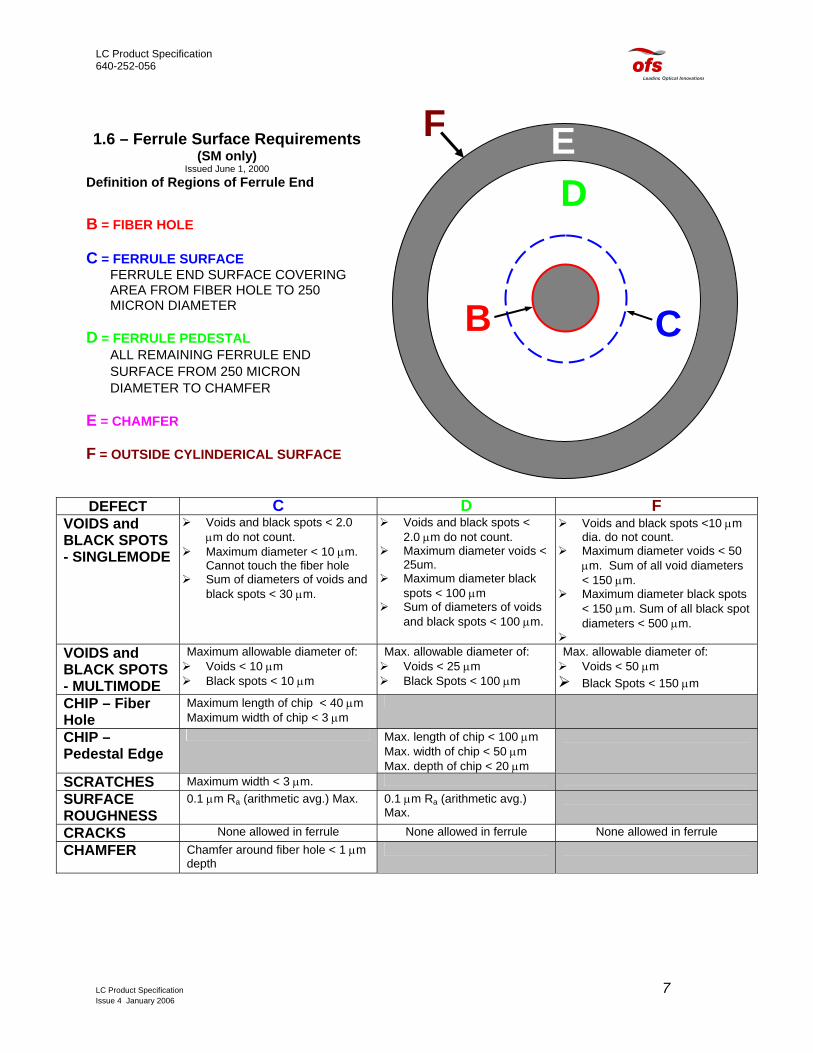
1.6 – Ferrule Surface Requirements(SM only)Issued June 1, 2000 Definition of Regions of Ferrule End
B = FIBER HOLE C = FERRULE SURFACE
FERRULE END SURFACE COVERING AREA FROM FIBER HOLE TO 250 MICRON DIAMETER
D = FERRULE PEDESTAL
ALL REMAINING FERRULE END SURFACE FROM 250 MICRON DIAMETER TO CHAMFER
E = CHAMFER F = OUTSIDE CYLINDERICAL SURFACE
DEFECT C D F IDS and
CK SPOTS NGLEMODE
Voids and black spots < 2.0 µm do not count.
Maximum diameter < 10 µm. Cannot touch the fiber hole
Sum of diameters of voids and black spots < 30 µm.
Voids and black spots < 2.0 µm do not count.
Maximum diameter voids < 25um.
Maximum diameter black spots < 100 µm
Sum of diameters of voids and black spots < 100 µm.
Voids and black spots <10 µm dia. do not count.
Maximum diameter voids < 50 µm. Sum of all void diameters < 150 µm.
Maximum diameter black spots < 150 µm. Sum of all black spot diameters < 500 µm.
IDS and
CK SPOTS ULTIMODE
Maximum allowable diameter of: Voids < 10 µm Black spots < 10 µm
Max. allowable diameter of: Voids < 25 µm Black Spots < 100 µm
Max. allowable diameter of: Voids < 50 µm Black Spots < 150 µm
IP – Fiber e
Maximum length of chip < 40 µm Maximum width of chip < 3 µm
IP – estal Edge
Max. length of chip < 100 µm Max. width of chip < 50 µm Max. depth of chip < 20 µm
ATCHES Maximum width < 3 µm.
FACE UGHNESS
0.1 µm Ra (arithmetic avg.) Max. 0.1 µm Ra (arithmetic avg.) Max.
ACKS None allowed in ferrule None allowed in ferrule None allowed in ferrule AMFER Chamfer around fiber hole < 1 µm
depth
LC Product Specification 7 Issue 4 January 2006

LC Product Specification 640-252-056
A
F
MECHANICALREFERENCE
PLANE
OPTICALREFERENCE
PLANE
1.7 - LC Connector Ferrule Extension and Contact Force
Requirements for ferrule travel and contact force: IF THEN
1 F = 0 A ≥ 10.45 mm 2 A ≤ 10.2 mm F ≥ 5 N (510 gf) 3 A ≥ 9.6 mm F ≤ 6 N (612 gf) Note: Dimension A is for finished ends after all polishing has been completed
1.8 - LC Reference Dimensions (inches) for Polishing Fixturing
LC Product Specification 8 Issue 4 January 2006

LC Product Specification 640-252-056
1.9 - LC Connector Coding (or equivalent)
P 1 2 00 A - Z - 125 | | | | | | |
Plug Series Type Style | Ferrule Fiber Size 0-MM 00-Jumper Plug | Z-Zirconia 1-SM 01-BTW Plug | 2-APC | | | Version
1.10 - LC Connector Color Coding
Connector Housing Color Cable Support Color SM Blue White MM Beige White APC Green White
LC Product Specification 9 Issue 4 January 2006
LC Product Specification 640-252-056
2.0 - LC Adapter Specification
LC Product Specification 10 Issue 4 January 2006

LC Product Specification 640-252-056
2.0 - LC Adapter Specification
2.1b - LC Simplex Adapter2.1a - LC Duplex Adapter
Jr. Side
Sr. Side
Jr. Side
Sr. Side
2.2a - LC Duplex Adapter Footprint Dimensions
C
B
A
2.2b - LC Simplex Adapter Footprint Dimensions
D
E
F
G
H
Sr. SideJr. Side Sr. SideJr. Side
REF. DIMENSIONS Minimum mm Maximum
A 25.0 30.0 B 13.0 13.1 C 13.0 13.1 D 25.0 30.0 E 11.5 11.6 F 6.9 7.0 G 10 10.1 H 14.55 14.65
LC Product Specification 11 Issue 4 January 2006

LC Product Specification 640-252-056
B D
C
E*
SimplexMounting
DuplexMounting Panel
Thickness
A
2.3 - Panel Cutout Dimensions for Mounting LC Adapters
Dimension Minimum (mm)
Maximum (mm)
A 11.7 11.8 B 7.1 7.2 C 13.2 13.4 D 13.2 13.4 E* 1.2 1.7
* Panel thickness “E” applies after surface preparation i.e. painting, etc.
2.4 - LC Adapter Materials
Connector Part Material UL 94 Rating Oxygen Index Adapter Housing Engineering Plastic V-0 50 SM Sleeve Zirconia - - MM Sleeve Metal - -
LC Product Specification 12 Issue 4 January 2006
LC Product Specification 640-252-056
J
AS
AR
⊕ 0.05 C AM
⊕ 0.05 C AM
C
E
D
b
b
AQ
APOPTICAL
REFERENCEPLANE
- A -
a
a
AO
I
AW AX
B
AT
G
AUAV
P
MECHANICALREFERENCE
PLANE
⊥ ∅ 0.025 A
⊕ ∅ 0.05 B A
A
OPTICALREFERENCE
PLANE
- B -
⊥ ∅ 0.025 A
L⊕ 0.05 B AM
H2
F
A⊕ 0.05 B
- C -
M
H1
N
Section a-a Section b-b
O
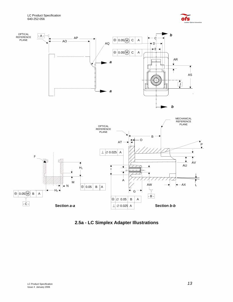
2.5a - LC Simplex Adapter Illustrations
LC Product Specification 13 Issue 4 January 2006

LC Product Specification 640-252-056
K
- B -
⊕ ∅ 0.10 BM M
2.5b - LC Duplex Adapter Illustrations
2.5c – LC Adapter Specifications for Intermateability
Dim. Min.
(mm) Max. (mm)
Notes
A - - diameter 1, 2, 3 B 9.9 10.0 C 4.5 - D 3.4 3.5 E 2.6 2.7 F 0.2 0.3 radius G 4.0 4.1 H1 4.65 4.75 H2 4.65 4.75 I 2.87 2.97 diameter J 2.29 basic dimension K 6.25 basic dimension L 0.0 0.2 degrees, 5 M 1.0 1.1 N 0.5 0.6 O - 1.2 P 15 - degrees, typical
AO 11.1 12.8 AP 14.5 14.7 AQ 2.2 2.4 radius AR 1.1 1.2 AS 6.6 6.8 AT 0.6 0.7
LC Product Specification 14 Issue 4 January 2006

LC Product Specification 640-252-056
AU 1.8 2.0 AV 1.0 1.1 AW 1.4 1.5 diameter AX 1.9 -
NOTE 1. The connector alignment feature is a resilient (split) alignment sleeve, and the
sleeve may be either fixed or floating. For a fixed sleeve the positional tolerance of dimension I applies to both A and I dimensions. For a floating sleeve, a gauge pin inserted in the sleeve must be capable to move freely into a position such that it is coincident with datum B. Dimension A defines the inner diameter of the alignment feature.
NOTE 2. The connector alignment feature is an alignment sleeve. The feature must
accept a pin gauge to the center of the adapter with a force of 1.0 N to 2.5 N under the condition that another pin gauge is inserted into the feature from the other side until both pin gauges butt against each other. The pin gauge shall be 1.2490 mm. The center of the adapter is defined by the left side position of dimension B.
NOTE 3. Each of the units in the duplex adapter shall comply with all of dimensions of
Figures 2.5a and 2.5b. NOTE 4. Taper, dimension L, is applied to the surfaces associated with
dimension/feature H1 and H2.
LC Product Specification 15 Issue 4 January 2006

LC Product Specification 640-252-056
Installfrom rear
Installfrom rear
Installfrom rear
Adapter MountedHorizontally
Adapter Mounted 90Counterclockwise
° Adapter Mounted 90Clockwise
°
2.6 - LC Duplex Adapter Mounting Options
Sr. Side
Jr. Side
2.7 - LC Adapter Coding (or equivalent)
C 1 2 0 0 B - 1 | | | | | | |
Adapter Series Type Style | Sleeve Ports 0-MM 0-LC to LC | A-Zirconia 1-Simplex 1-SM | B-Metal 2-Duplex 2-APC | Version 0-Flanged 1-Flanged with Sr. and Jr. Profiles
2.8 - LC Adapter Color Coding
Adapter Housing Color SM Blue MM Beige APC Green
LC Product Specification 16 Issue 4 January 2006

LC Product Specification 640-252-056
3.0 – LC Device Receptacle Specification
LC Product Specification 17 Issue 4 January 2006

LC Product Specification 640-252-056
3.0 - LC Device Receptacle Specification
3.1a - LC Simplex Device Receptacle - Front View
3.1b - LC Simplex Device Receptacle – Rear View
SPECIFICATIONS
• Compliant with FOCIS 10 Connector Standard (to be TIA/EIA-604-10).
• Housing material is an engineered thermoplastic.
• Non-keyed connector adapter housing.
• Housing accepts a ferrule alignment and device insert.
• Insert provides LC ferrule stop and known optical reference plane.
• Device insert bore is cylindrical, with non-rotation flat in outer diameter.
• Two-piece design aids in device installation.
• The assembled adapter is mounted using the molded-in cantilever latching arms.
• Includes one simplex LC bore dust cover.
FEATURES This device adapter couples one singlemode LC connector to customer supplied transmitting or receiving device. The simplex LC half of this device follows the small form-factor LC adapter standard. Two-piece design allows customers to install a ferrule alignment and device insert inside the housing. Once the device is mounted in the insert, and the insert assembly is installed into the device adapter housing, the rear-housing unit is pressed onto the retaining pins.
11.5[.45]
9.6 [.38]
6.9 [.27]
METRIC MILLIMETERS [INCHES]
17.8 [.70]
13.5 [.53]
LC Product Specification 18 Issue 4 January 2006
9.4 [ 37]

LC Product Specification 640-252-056
3.2a - LC Duplex Device Receptacle – Front View
3.2b - LC Duplex Device Receptacle – Rear View
SPECIFICATIONS • Compliant with FOCIS
10 Connector Standard (to be TIA/EIA-604-10).
• Housing material is a glass filled thermoplastic.
• Non-keyed connector adapter housing.
• Positive LC ferrule stop, provides known optical reference plane.
• Single piece design, with mounting clip.
• Clip has solder-able mounting tabs. Tab widths are 0.040 in. and spaced 0.400 in.
• Single cylindrical device bore, with non-rotation tab notch.
• Vented device bores.
• Includes two simplex LC bore dust covers.
FEATURES This device adapter will couple one or two simplex, or a duplex multimode LC connector to customer supplied transmitting and receiving devices. The duplex LC half of this device follows the small form-factor LC adapter standards. Single piece design, with mounting clip, allows customers to install devices and mount the adapter to electronic wiring boards. Securing the device adapter will be done by means of solder-able tabs on the retaining clip.
LC Product Specification 19 Issue 4 January 2006
LC Product Specification 640-252-056
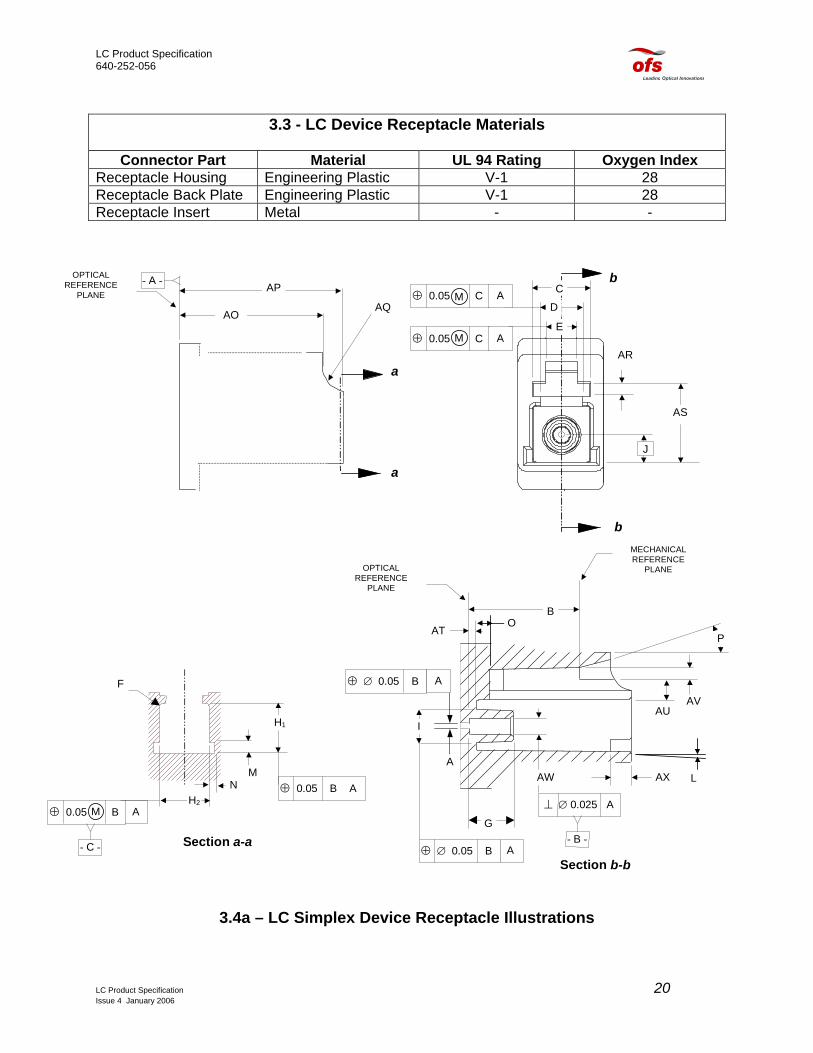
3.3 - LC Device Receptacle Materials
Connector Part Material UL 94 Rating Oxygen Index
Receptacle Housing Engineering Plastic V-1 28 Receptacle Back Plate Engineering Plastic V-1 28 Receptacle Insert Metal - -
J
AS
AR
⊕ 0.05 C AM
⊕ 0.05 C AM
b
b
AQ
APOPTICAL
REFERENCEPLANE
- A -
a
a
AO
C
D
E
A
I
AW AX
B
AT
G
AUAV
P
MECHANICALREFERENCE
PLANE
⊥ ∅ 0.025 A
- B -⊕ ∅ 0.05 B A
⊕ ∅ 0.05 B A
OPTICALREFERENCE
PLANE
L⊕ 0.05 B A
M
H2
F
A⊕ 0.05 B
- C -
M
H1
N
Section a-a
Section b-b
O
3.4a – LC Simplex Device Receptacle Illustrations
LC Product Specification 20 Issue 4 January 2006

LC Product Specification 640-252-056
K
- B -
⊕ ∅ 0.10 BM M
3.4b - LC Duplex Device Receptacle Illustrations
3.4 – LC Device Receptacle Specifications for Intermateability
Dim. Min.
(mm) Max. (mm)
Notes
A 0.5 0.8 See Grade Table 3b B 9.9 10.0 C 4.5 - D 3.4 3.5 E 2.6 2.7 F 0.2 0.3 radius G 4.0 4.1 H1 4.65 4.75 H2 4.65 4.75 I 2.87 2.97 diameter J 2.29 basic dimension K 6.25 basic dimension, 3 L 0.2 0.0 degrees, 4 M 1.0 1.1 N 0.5 0.6 O - 1.2 P 15 - degrees, typical
AO 12.6 12.8 AP 14.5 14.7 AQ 2.2 2.4 radius AR 1.1 1.2 AS 6.6 6.8 AT 0.6 0.7
LC Product Specification 21 Issue 4 January 2006

LC Product Specification 640-252-056
AU 1.8 2.0 AV 1.0 1.1 AW - - See GRADE TABLE 3b AX 1.9 -
NOTE 1. The connector alignment feature is a rigid bore sleeve or a resilient alignment
sleeve. Dimension AW defines the inner diameter of the alignment feature. NOTE 2. The sleeve may be fixed or floating. For a fixed sleeve, the positional tolerance
applies. For a floating sleeve, a gauge pin inserted in the sleeve must be capable to move freely into a position such that it is coincident with datum B.
NOTE 3. Each of the units in the duplex receptacle shall comply with all of dimensions of
Figures 3.4a and 3.4b. NOTE 4. Taper, dimension L, is applied to the surfaces associated with
dimension/feature H1 and H2
3.5 - Active Device Receptacle Interface - Alignment Sleeve Grade
N (mm) GRADE
MIN MAX NOTES
1 1.251 1.252 rigid bore sleeve, 1, 3 2 1.251 1.254 3 1.251 1.257 4 resilient alignment
sleeve, 2, 3 NOTE 1. The connector alignment feature is a rigid bore sleeve. The dimension A shall
be tested using two pin gauges. One pin gauge has the pin gauge grade number 1 µm larger than the maximum value of dimension A, the other pin gauge has the number pin gauge grade number 1 µm smaller than the minimum value of dimension A. The appropriate pin gauge shall be selected from the pin gauge grade table.
NOTE 2. The connector alignment feature is a resilient (split) alignment sleeve. The
feature must accept a pin gauge completely to the left side of dimension G with a force of 1.0 N to 2.5 N. Insert the pin gauge completely, from only one side, the connector side of the active device receptacle interface. The pin gauge is defined in Table 4.
LC Product Specification 22 Issue 4 January 2006

LC Product Specification 640-252-056
∅ CK
C or R
CN
∅ CL
3.6 - Pin Gauge for Active LC Device Receptacle
3.7 – Pin Gauge Grade
PIN CK CL CN GAUGE (mm) (mm) (mm) NOTES GRADE MIN MAX MIN MAX MIN MAX
1.249 1.2485 1.2495 2.6 4.4 4.2 15 resilient sleeve, 1 1.250 1.2495 1.2505 1.253 1.2525 1.2535 rigid bore sleeve, 1 1.255 1.2545 1.2555 1.258 1.2575 1.2585
NOTE 1. Surface roughness should be 0,2 µm Ra and cylindricity is less than 0,5 µm.
3.8 - LC Device Receptacle Coding (or equivalent)
R 1 1 0 1 B - 3 | | | | | | |
Receptacle Ports Performance Style 0-No Latch Interface Device Side 1-Simplex 0-Standard 0- No Pin 1-Latch A-Std.
Ferrule Stop
1-Stepped Bore
2-Duplex 1-High Perf. 1-Pin B-Bushing 2-Full Bore 2- Threaded C-Lens
Cavity 3-Type “A”
Bushing 3-Clip 4-Type “B”
Bushing 4-Cover
3.9 - LC Device Receptacle Color Code
Device Receptacle Housing Color
SM Blue MM Black
LC Product Specification 23 Issue 4 January 2006

LC Product Specification 640-252-056
4.0 – LC Attenuator Specification
LC Product Specification 24 Issue 4 January 2006

LC Product Specification 640-252-056
4.0 - LC Attenuator Specification
Dust Cap
Attenuated Cap
BasePanel
Sleeve
Attenuator Element
4.1 - LC Attenuator Buildout System (Exploded View)
4.2 - LC Split Adapter/Attenuator Footprint Illustration
LC Product Specification 25 Issue 4 January 2006

LC Product Specification 640-252-056
4.3 - LC Attenuator Materials and Specifications
Connector Part Material UL 94 Rating Oxygen Index
Attenuator Cap Engineering Plastic V-0 48 Base Engineering Plastic V-0 48 Attenuator Element Optical Plastic H.B T.B.D Attenuator Sleeve Zirconia - -
Specifications: Units Value Physical LC Split Adapter Type Cap Color 0 dB = Blue, Attenuator = YellowBase Color Black Transmission Singlemode Nominal Attenuation @ 1550 nm and 0 dBm dB See Table-1 below Attenuation Tolerance @ 1550 nm and 0 dBm dB See Table-1 below Maximum Spectral Attenuation Variation (1300 to 1620 nm)
dB See Note 1
Maximum Attenuation Variation Due to Incident Power
dB See Note 2
Maximum Incident Optical Power Handling Capability dBm 25 Reflectance dB Typically = –34, Maximum = -30 Operating Temperature °C -40 to 75 Matings over Life 200 Qualification Tests and Applicable Standards See Table - 2
LC Product Specification 26 Issue 4 January 2006

LC Product Specification 640-252-056
4.4 – SM Attenuation Levels and Performance All numbers apply for 1550 nm and 0 dBm signals
PRODUCT
CODE ORDER
COMCODE NOMINAL*
LOSS (dB)
TYPICAL STANDARD DEVIATION IN LOSS
(dB)
NOMINAL LOSS TOLERANCE
+/- (dB)
AALCS-00.5 108355363 0.5 .08 0.25 AALCS-01.0 108355371 1 .08 0.25 AALCS-01.5 108355389 1.5 .08 0.25 AALCS-02.0 108349457 2 .08 0.25 AALCS-02.5 108349440 2.5 .08 0.25 AALCS-03.0 108288481 3 .08 0.25 AALCS-03.5 108288440 3.5 .08 0.25 AALCS-04.0 108357963 4 .08 0.25 AALCS-04.5 108357971 4.5 .08 0.25 AALCS-05.0 108288473 5 .08 0.25 AALCS-05.5 108357989 5.5 .08 0.25 AALCS-06.0 108349432 6 .08 0.25 AALCS-06.5 108357997 6.5 .08 0.25 AALCS-07.0 108288465 7 .08 0.25 AALCS-07.5 108358003 7.5 .08 0.25 AALCS-08.0 108358011 8 .08 0.25 AALCS-08.5 108358029 8.5 .10 0.25 AALCS-09.0 108358037 9 .10 0.25 AALCS-09.5 108358045 9.5 .10 0.25 AALCS-10.0 108288457 10 .10 0.25 AALCS-11.0 108358078 11 .12 0.50 AALCS-12.0 108358094 12 .12 0.50 AALCS-13.0 108358128 13 .12 0.50 AALCS-14.0 108358144 14 .12 0.50 AALCS-15.0 108358169 15 .12 0.50 AALCS-18.0 108358193 18 .12 0.50 AALCS-19.0 108358201 19 .15 0.50 AALCS-20.0 108358219 20 .14 0.50 *The caps are laser marked with the nominal attenuation (dB)
LC Product Specification 27 Issue 4 January 2006

LC Product Specification 640-252-056
4.5 - LC Attenuator Compliance to GR-910-CORE
Tests Compliance Notes
Baseline IL/RL Yes Damage Yes
Thermal Aging Yes Thermal Cycling Yes
Humidity/Condensation Yes Dry Out-Thermal Cycle Yes
Vibration Not Tested to GR-910-CORE Tested to GR-63-CORE Flex Yes Twist Yes Proof Yes
Transmission w/Applied Load Yes Durability Yes
Impact Yes End of Test Yes
LC Product Specification 28 Issue 4 January 2006
LC Product Specification 640-252-056
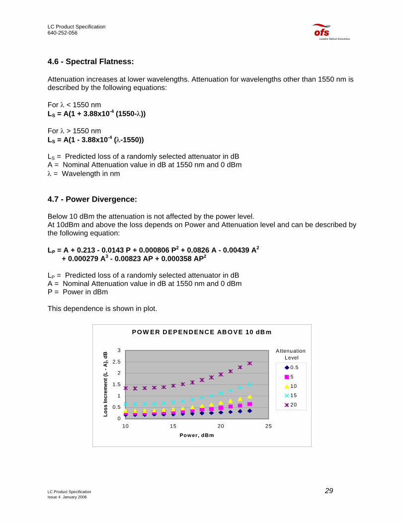
4.6 - Spectral Flatness: Attenuation increases at lower wavelengths. Attenuation for wavelengths other than 1550 nm is described by the following equations: For λ < 1550 nm LS = A(1 + 3.88x10⁻⁴ (1550-λ)) For λ > 1550 nm LS = A(1 - 3.88x10⁻⁴ (λ-1550)) LS = Predicted loss of a randomly selected attenuator in dB A = Nominal Attenuation value in dB at 1550 nm and 0 dBm λ = Wavelength in nm 4.7 - Power Divergence: Below 10 dBm the attenuation is not affected by the power level. At 10dBm and above the loss depends on Power and Attenuation level and can be described by the following equation: LP = A + 0.213 - 0.0143 P + 0.000806 P2 + 0.0826 A - 0.00439 A2 + 0.000279 A3 - 0.00823 AP + 0.000358 AP2 LP = Predicted loss of a randomly selected attenuator in dB A = Nominal Attenuation value in dB at 1550 nm and 0 dBm P = Power in dBm This dependence is shown in plot.
POW ER DEPENDENCE ABOVE 10 dBm
0
0.5
1
1.5
2
2.5
3
10 15 20 25
Power, dBm
Loss
Incr
emen
t (L
- A),
dB
0.5
5
10
15
20
Attenuation Level
LC Product Specification 29 Issue 4 January 2006
LC Product Specification 640-252-056
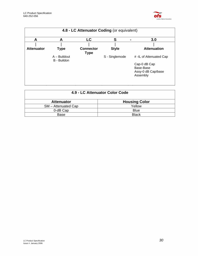
4.8 - LC Attenuator Coding (or equivalent)
A A LC S - 3.0 | | | | |
Attenuator Type Connector Type
Style Attenuation
A – Buildout B - Buildon
S - Singlemode # -IL of Attenuated Cap
Cap-0 dB Cap Base-Base Assy-0 dB Cap/base
Assembly
4.9 - LC Attenuator Color Code
Attenuator Housing Color
SM – Attenuated Cap Yellow 0-dB Cap Blue
Base Black
LC Product Specification 30 Issue 4 January 2006

LC Product Specification 640-252-056
5.0 – LC Jumper Specification
LC Product Specification 31 Issue 4 January 2006

LC Product Specification 640-252-056
5.0 - LC Jumper Specification
5.1 - LC Simplex Jumper on 1.6mm Cordage
5.2 - LC Simplex Jumper Exploded Assembly
Narrow End of Cable Support
Cable Support
Metal End of Crimp Sleeve
Heat Shrink TubingCrimp Sleeve Sub-ssembly
LC Product Specification 32 Issue 4 January 2006

LC Product Specification 640-252-056
Duplex yokeMM Only
Cable support
Crimp sleeve(yellow)
Cable support
Blue buffer
Duplex yokeMM Only
B channelopening
B channelopening
A channelopening
A channelopening
Cable support
Crimp sleeve(yellow)
Crimp sleeve(white)
Cable support
Blue buffer
Orange buffer
5.3 - LC Duplex Jumper Exploded Assembly
End1 Channel B
5.4 - LC Duplex MM Jumper as per TIA/EIA
End 2 Channel BEnd 1 Channel A
End 2 Channel AOrange Fiber
Blue Fiber
LC Product Specification 33 Issue 4 January 2006

LC Product Specification 640-252-056
5.5 - LC Jumper/Connector Materials
Connector Part Material UL 94 Rating Oxygen Index
Connector Housing Engineering Plastic V-0 50 Extender Cap Engineering Plastic V-0 50 Strain Relief Boot Thermoplastic Rubber H.B 23 Heat Shrink Tubing Polyolefin UL/CSA Recognized T.B.D. Buffer Adapter PVC V-0 29 Duplex Clip Nylon H.B. 24 Spring Metal - - Ferrule Zirconia - - Crimp Sleeve Metal - - Jumper Ext. Cap Insert Metal - - Barrel Metal - - 1.6mm Minicord UL 1666 Jacket PVC Buffer Nylon Strength Material Arimid Yarn
5.6 - Minicord® Technical Specifications Multimode Fiber, Core/Cladding 62.5/125 microns Singlemode Fiber, Core/Cladding 8.3/125 microns Fiber Coating 250 micron Buffer Diameter 0.9 mm Jacket Diameter 1.6 mm Fiber Proof Test 100 CPIs (689 N/mm2) Cordage Proof Test 20 lb. (88.9 N)
LC Product Specification 34 Issue 4 January 2006

LC Product Specification 640-252-056
Note: The dimensions in table below are for reference only and apply after polishing procedures have been completed.
5.7 - LC Singlemode Ferrule Endface Geometry
Item Reference Minimum Nominal Maximum DimensionsRadius A 7 12 25 mm
Pedestal∗ B 0.6 --- 0.85 mm Dome ECC. — 0 — 0.050 mm
Chamfer C 25 30 35 degrees Undercut D — — See Graph A nm Protrusion E — — 50 nm
* - Pedestal diameter after polishing.
Acceptable values under the curve
Graph A. Recommended Fiber Undercut (Table Reference D)
LC Product Specification 35 Issue 4 January 2006
LC Product Specification 640-252-056
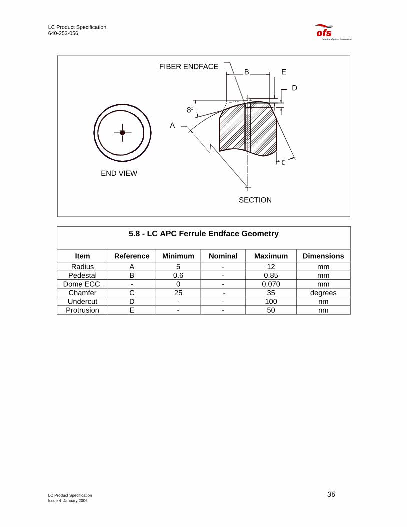
D
EFIBER ENDFACE
8°
B
A
SECTION
END VIEWC
5.8 - LC APC Ferrule Endface Geometry
Item Reference Minimum Nominal Maximum Dimensions Radius A 5 - 12 mm
Pedestal B 0.6 - 0.85 mm Dome ECC. - 0 - 0.070 mm
Chamfer C 25 - 35 degrees Undercut D - - 100 nm Protrusion E - - 50 nm
LC Product Specification 36 Issue 4 January 2006

LC Product Specification 640-252-056
8°
5.9 - LC APC Ferrule/Angle Orientation
TOP VIEW
Connector Latch
5.10 - LC Factory Made PC Patch Cord – Specifications
Fiber Type Singlemode PC APC Multimode Loss1: Avg./Std. Dev. 0.08 dB/0.07 dB (Tuned)* 0.08 dB/0.06 dB 0.10 dB/0.10 dB Loss1: Maximum 0.25 dB3
0.15 dB (BT)40.30 dB
0.15 dB (BT)40.5
Return Loss Minimum 55 dB 65 dB 20 dB Cable Retention2 (1.6mm) 0° Axial Pull
10 lbs./44.5 N 10 lbs./44.5 N 10 lbs./44.5 N
Mating Durability (500 Reconnects) Insertion Loss Change
< 0.2 dB
< 0.2 dB
< 0.2 dB
Temp. Stability (-40 °C to 75 °C) Insertion Loss Change
< 0.3 dB
< 0.3 dB
< 0.3 dB
1 Complete connection concatenated statistics 8.8/125 fiber, 62.5/125 fiber. Dry connection. 2 Values represent axial force on connector with axial pull on cordage. See cordage requirements in Section 5.6. Cable dependent to cause permanent light transmission failure. Figures representative of use with OFS jumper cordage or equivalent. 3 * The performance is representative of all LC factory patchcords herein. Xmax + 2σ = 0.22 dB, Xmax + 3σ = 0.30 dB. Performance representative of product - to - product or product - to - OFS “Golden Reference Jumper” (Part No. 108513045). 4 BT = Blue Tiger Patchcord
LC Product Specification 37 Issue 4 January 2006

LC Product Specification 640-252-056
5.11 - Visual Inspection Criteria for Fiber Optic Connectors with Fiber Issued: February 2000
Figure 2- Definition of regions and defects
CRA
CHIP
PIN
SCR
SCRAnd
FEREPO
FIXEBLA
RAISLOO
E
FIBER-OD
F
D
C B
A = RESTRICTED AREA A=(fiber OD+d)/2 Fiber OD=125 microns d- is the core diameter of the fiber d for SM = 8 microns d for MM is 62 microns A=66 microns for SM fiber A=95 microns for MM fiber B = FIBER SURFACE AREA OUTSIDE RESTRICTED “A” TO EDGE OF FIBER(125 UM) C = FERRULE SURFACE
FERRULE AREA COVERING AREA FROM 125 TO 250 MICRONSD = FERRULE PEDESTAL E = CHAMFER F=OUTSIDE CYLINDRICAL SURFACE
DEFECT A B
CK not acceptable No Cracks when extended can intersect the core
not acceptable One defect up to 10um in diameter is acceptable Defect <2.0 um don’t count
Multiple defeacceptable (cDefects <2.0Sum of all d
HOLES/VOIDS Multiple defeacceptable (cDefects <2.0Sum of all d
ATCHES (SM) No scratches in core Tangent to core acceptable if less than 2 um width
Scratches are acceptable if they do not exceed
2um width
ATCHES (MM APC connectors)
Scratches in the core are acceptable if transmission requirements are met
Scratches are acceptable if they do not exceed
2um width
RULE SCRATCHES No sc
XY RING Epoxy ring is acceptable if the width is less than 5 um
D CONTAMINATION CK SPOTS
not acceptable One defect up to 10um in diameter is acceptable Defect <2.0 um don’t count
Multiple defeacceptable (cDefects <2.0Sum of all d
ED CONTAMINATION not acceptable not acceptable noSE CONTAMINATION not acceptable not acceptable no
LC Product Specification Issue 4 January 2006
E
C
cts <10uan’t tou
um do nefect tycts <10uan’t tou
um do nefect ty
ratches
cts <10uan’t tou
um do nefect tyt acceptt accept
d
A
D-F N/A polished end See Ferrule Spec
m each are ch fiber edge) ot count
pes<30um
N/A for polished end
See Ferrule Spec
m each are ch fiber edge) ot count
pes<30um
N/A for polished end
See Ferrule Spec
> 2 um acceptable
m each are ch fiber edge) ot count
pes<30um
acceptable
able acceptable
able acceptable
38
LC Product Specification 640-252-056
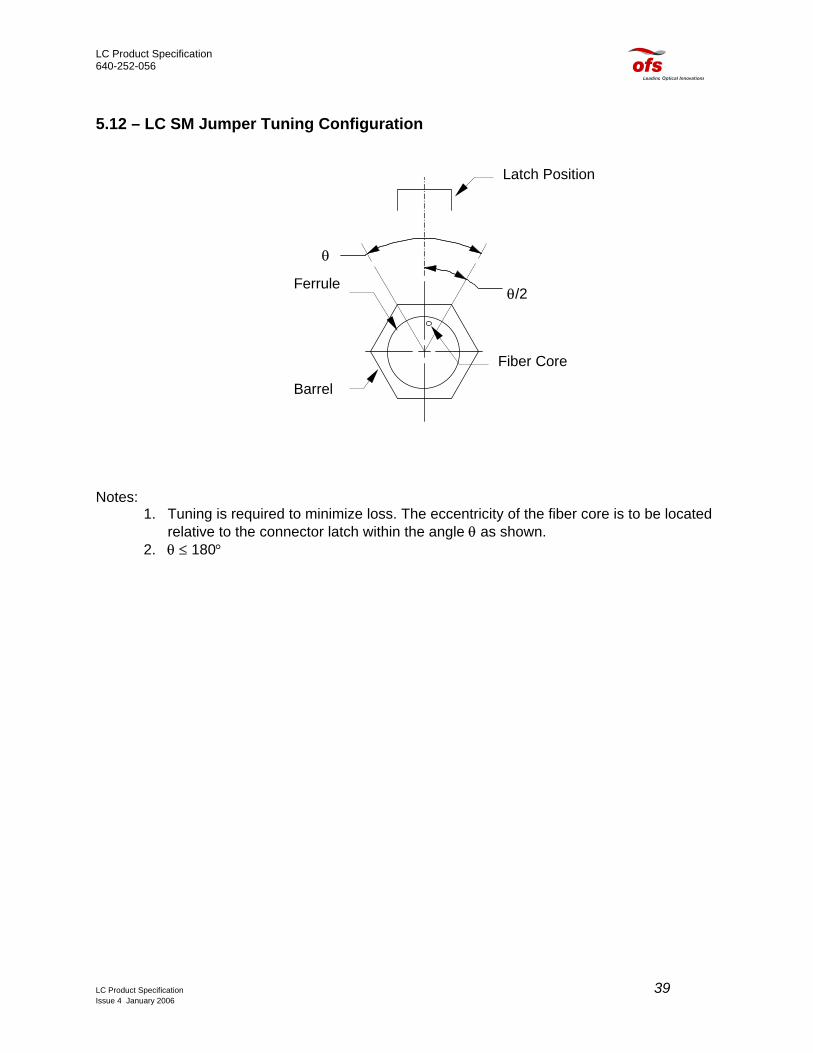
5.12 – LC SM Jumper Tuning Configuration
θ/2
θ
Latch Position
Ferrule
Barrel
Fiber Core
Notes: 1. Tuning is required to minimize loss. The eccentricity of the fiber core is to be located
relative to the connector latch within the angle θ as shown. 2. θ ≤ 180°
LC Product Specification 39 Issue 4 January 2006
LC Product Specification 640-252-056
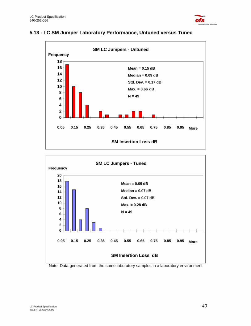
5.13 - LC SM Jumper Laboratory Performance, Untuned versus Tuned
SM LC Jumpers - Untuned
02468
1012141618
0.05 0.15 0.25 0.35 0.45 0.55 0.65 0.75 0.85 0.95 More
SM Insertion Loss dB
Frequency
Mean = 0.15 dB
Median = 0.09 dB
Std. Dev. = 0.17 dB
Max. = 0.66 dB
N = 49
SM LC Jumpers - Tuned
02468
101214161820
0.05 0.15 0.25 0.35 0.45 0.55 0.65 0.75 0.85 0.95 More
SM Insertion Loss dB
Frequency
Mean = 0.09 dB
Median = 0.07 dB
Std. Dev. = 0.07 dB
Max. = 0.28 dB
N = 49
Note: Data generated from the same laboratory samples in a laboratory environment
LC Product Specification 40 Issue 4 January 2006

LC Product Specification 640-252-056
LC-LC Duplex Jumper on 1.6 mm Cordage Shown
Length Per Code6” Min. to 12” Max.
154.2mm to 226.6mm
5.14 - LC Jumpers - Available Configurations
LC-LC LC-SC LC-FC LC-ST SM & MM SM & MM SM & MM SM & MM
Simlex & Duplex Simplex & Duplex Simplex & Duplex Simplex & Duplex
Feet Available Lengths and Tolerances Meters 4 +0.5/-0 1.2 +0.15/-0 5 +0.5/-0 1.5 +0.15/-0 6 +0.5/-0 1.8 +0.15/-0 8 +0.5/-0 2.4 +0.15/-0 10 +0.5/-0 3.1 +0.15/-0 15 +1/-0 4.6 +0.3/-0 20 +1/-0 6.1 +0.3/-0 25 +1/-0 7.6 +0.3/-0 30 +1/-0 9.2 +0.3/-0 35 +1/-0 10.7 +0.3/-0 40 +1/-0 12.2 +0.3/-0 50 +1/-0 15.2 +0.3/-0 75 +1/-0 22.9 +0.3/-0 100 +1/-0 30.5 +0.3/-0
LC Product Specification 41 Issue 4 January 2006

LC Product Specification 640-252-056
5.15 - LC Jumper Coding (or equivalent)
M S 2 LC - LC - 10 | | | | |
Cordage Type
Fiber Type Jumper Type
Connector Type (end 1)
Connector Type (end 2)
Length (ft)
M - Minicord S-SM 1-Simplex LC for LC LC for LC L- MM (62.5) 2-Duplex LCA for LC
Angled LCA for LC
Angled
B - SBJ V-Matched Clad 4-Quad LCB for LC Backlight
BCB for LC Backlight
N - Nylon Buffer W-Allwave T-Truewave+
FC for FC
F-Truewave- FCA for FC Angled
Z-Lazerspeed D4 for D4 EP for STII+ SC for SC
Variations: R- Red Jacket, S-Staggered Ends, G-Reference\Golden. Note: Variation code specified in the third digit (MSB, MSR, MSY) or the forth digit (MS1G) or the (MS2LC-SLC)
5.16 - LC Jumper Color Coding
Jumper Connector Color Cordage Color SM Blue w/White Boot Yellow
MM 62.5 µm Beige w/White Boot Slate (Gray) APC Green w/Green Boot Yellow
LC Product Specification 42 Issue 4 January 2006

LC Product Specification 640-252-056
6.0 – LC Product Specification – Data
LC Product Specification 43 Issue 4 January 2006

LC Product Specification 640-252-056
6.0 - LC Product Specification Data
Fiber Optic Apparatus Qualification Laboratory
1997 Test Report – Singlemode LC MinicordTM Jumper.
• 15 SM jumpers randomly selected from Aug 97 production, manufactured by OFS Technology Atlanta Facility.
• Pass/fail determinations for each test: Telcordia GR-326 and OFS Product
Specifications. 6.1 - Telcordia GR-326 Optical Performance Criteria (1997) Insertion Loss (IL) Requirement ObjectiveMaximum IL 0.30 dB 0.20 dB Mean IL 0.20 dB 0.15 dB Return Loss (RL) Requirement Objective Maximum RL 40 dB 50dB
OFS LC New Product Specification Insertion Loss (IL) Average Std. Dev.Factory Tuned 0.08 dB 0.07 dB Field Installed 0.20 dB 0.10 dB Return Loss (RL) MinimumFactory 1997 50 dB Factory 1999 55 dB Field 1999 50 dB Notes: 1 Complete connection 8.8/125 fiber. Dry connection 2 Figures representative of use with OFS jumper cordage or equivalent. 3 The performance representative herein of LC factory patchcords that were produced and tested at OFS Atlanta Facility according toTelecordia 1997 GR-326
LC Product Specification 44 Issue 4 January 2006

LC Product Specification 640-252-056
6.2 - Telcordia GR-326 1997 Test Descriptions
Test Description
Passing Requirement
Passing Objective
Test Protocol (15 Samples)
New Product Testing Insertion Loss 0.30 dB Max.
15/15 0.20 dB Max. OFS in 1997 ≥ 50 dB RL
IL Increase 0.20 dB Max. Yes
0.15 dB Max. OFS in 1999 ≥ 55 dB RL
Return Loss 40 dB Min. 15/15
55 dB Min.
Thermal Aging Insertion Loss 0.40 dB Max.
15/15 0.30 dB Max. Measurement every 6 hours
IL Increase 0.30 dB Max. 15/15
0.20 dB Max. Post-test Criteria apply
Return Loss 40 dB Min. 15/15
55 dB Min.
Humidity Insertion Loss 0.40 dB Max.
15/15 0.30 dB Max. Measurement every 6 hours
IL Increase 0.30 dB Max. 15/15
0.20 dB Max. Criteria listed apply both during and after test
Return Loss 40 dB Min. 15/15
55 dB Min.
Thermal Cycle Insertion Loss
0.40 dB Max.
15/15
0.30 dB Max.
1 hr hold points at –40C°, 23C°, and 75C°. Measurement following 30 min. at hold points.
IL Increase 0.30 dB Max. 15/15
0.20 dB Max. Criteria listed apply both during and after test
Return Loss 40 dB Min. 15/15
55 dB Min.
Note: Test samples were allowed to reach thermal equilibrium for at least 2 hr. at 23 C before IL and RL measurements were made at the start and finish of each test.
LC Product Specification 45 Issue 4 January 2006
LC Product Specification 640-252-056
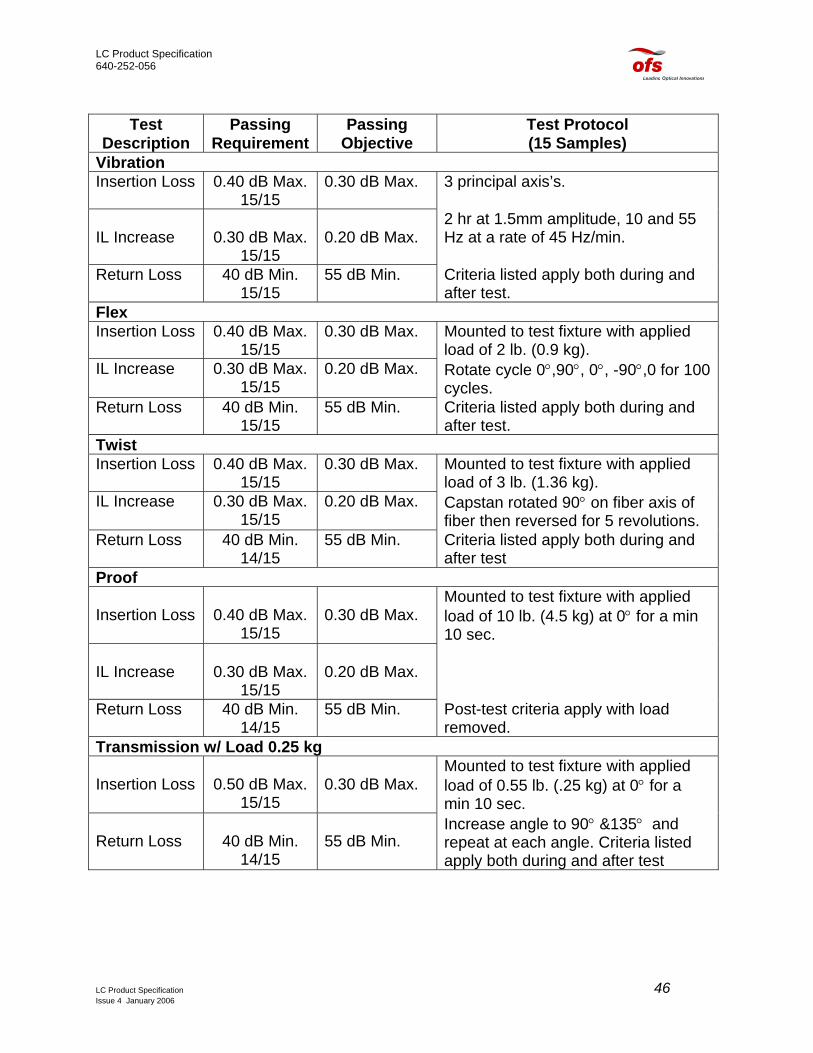
Test
Description Passing
Requirement Passing
Objective Test Protocol (15 Samples)
Vibration Insertion Loss 0.40 dB Max.
15/15 0.30 dB Max. 3 principal axis’s.
IL Increase
0.30 dB Max.
15/15
0.20 dB Max.
2 hr at 1.5mm amplitude, 10 and 55 Hz at a rate of 45 Hz/min.
Return Loss 40 dB Min. 15/15
55 dB Min. Criteria listed apply both during and after test.
Flex Insertion Loss 0.40 dB Max.
15/15 0.30 dB Max. Mounted to test fixture with applied
load of 2 lb. (0.9 kg). IL Increase 0.30 dB Max.
15/15 0.20 dB Max. Rotate cycle 0°,90°, 0°, -90°,0 for 100
cycles. Return Loss 40 dB Min.
15/15 55 dB Min. Criteria listed apply both during and
after test. Twist Insertion Loss 0.40 dB Max.
15/15 0.30 dB Max. Mounted to test fixture with applied
load of 3 lb. (1.36 kg). IL Increase 0.30 dB Max.
15/15 0.20 dB Max. Capstan rotated 90° on fiber axis of
fiber then reversed for 5 revolutions. Return Loss 40 dB Min.
14/15 55 dB Min. Criteria listed apply both during and
after test Proof Insertion Loss
0.40 dB Max.
15/15
0.30 dB Max.
Mounted to test fixture with applied load of 10 lb. (4.5 kg) at 0° for a min 10 sec.
IL Increase
0.30 dB Max.
15/15
0.20 dB Max.
Return Loss 40 dB Min. 14/15
55 dB Min. Post-test criteria apply with load removed.
Transmission w/ Load 0.25 kg Insertion Loss
0.50 dB Max.
15/15
0.30 dB Max.
Mounted to test fixture with applied load of 0.55 lb. (.25 kg) at 0° for a min 10 sec.
Return Loss
40 dB Min.
14/15
55 dB Min.
Increase angle to 90° &135° and repeat at each angle. Criteria listed apply both during and after test
LC Product Specification 46 Issue 4 January 2006

LC Product Specification 640-252-056
Test
Description Passing
Requirement Passing
Objective Test Protocol (15 Samples)
Transmission w/ Load 0.7 kg Insertion Loss 0.50 dB Max.
15/15 0.30 dB Max. Increase load to 1.54 lb.
(0.7 kg) repeat IL and RL Return Loss 40 dB Min.
14/15 55 dB Min. measurements at 0° and 90°.
Transmission w/ Load 1.5 kg Insertion Loss 0.50 dB Max.
15/15 0.30 dB Max. Increase load to 3.3 lb. (1.5 kg)
repeat IL and RL Return Loss 40 dB Min.
14/15 55 dB Min. measurements at 0° and 90°.
Transmission w/ Load 2.0 kg Insertion Loss 0.50 dB Max.
15/15 0.30 dB Max. Increase load to 4.4 lb. (2 kg) repeat
IL and RL Return Loss 40 dB Min.
14/15 55 dB Min. measurements at 0° and 90°.
Mating Durability Insertion Loss
0.40 dB Max.
15/15
0.30 dB Max.
Reconnect 200 times, both connectors cleaned after cycles 0, 50, 100, 150 and 200; mating connectors cleaned after 25, 50, 75, 125, and 175.
IL Increase
0.30 dB Max.
15/14
0.20 dB Max.
Measurement on cycle immediately before and after each cleaning.
Return Loss 40 dB Min. 14/15
55 dB Min. Criteria listed apply for each measurement.
Impact Insertion Loss
0.50 dB Max. 15/15
0.30 dB Max.
Mount one connector (jumper) on fixture. Raise connector to
IL Increase
0.30 dB Max. 15/15
0.20 dB Max.
Horizontal position, drop so connector impacts on block.
Return Loss
40 dB Min. 14/15
55 dB Min.
Repeat 8 times. Post-test criteria apply
End of Test Insertion Loss
0.40 dB Max. 14/15
0.30 dB Max.
For this lot, Mean IL of 0.12 dB including fusion splices.
IL Increase
0.30 dB Max. Yes
0.20 dB Max.
Std. Dev. = 0.08 dB, for both 1310/1550 nm.
Return Loss
40 dB Min. 15/15
55 dB Min.
For this lot 56.6 dB RL, for both 1310/1550 nm.
LC Product Specification 47 Issue 4 January 2006
LC Product Specification 640-252-056
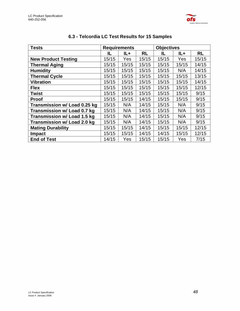
6.3 - Telcordia LC Test Results for 15 Samples
Tests Requirements Objectives IL IL+ RL IL IL+ RL New Product Testing 15/15 Yes 15/15 15/15 Yes 15/15 Thermal Aging 15/15 15/15 15/15 15/15 15/15 14/15 Humidity 15/15 15/15 15/15 15/15 N/A 14/15 Thermal Cycle 15/15 15/15 15/15 15/15 15/15 13/15 Vibration 15/15 15/15 15/15 15/15 15/15 14/15 Flex 15/15 15/15 15/15 15/15 15/15 12/15 Twist 15/15 15/15 15/15 15/15 15/15 9/15 Proof 15/15 15/15 14/15 15/15 15/15 9/15 Transmission w/ Load 0.25 kg 15/15 N/A 14/15 15/15 N/A 9/15 Transmission w/ Load 0.7 kg 15/15 N/A 14/15 15/15 N/A 9/15 Transmission w/ Load 1.5 kg 15/15 N/A 14/15 15/15 N/A 9/15 Transmission w/ Load 2.0 kg 15/15 N/A 14/15 15/15 N/A 9/15 Mating Durability 15/15 15/15 14/15 15/15 15/15 12/15 Impact 15/15 15/15 14/15 14/15 15/15 12/15 End of Test 14/15 Yes 15/15 15/15 Yes 7/15
LC Product Specification 48 Issue 4 January 2006

LC Product Specification 640-252-056
6.4 – Test Data
LC PreTest & PostTest IL 1997
0
0.2
0.4
0.6
0.8
1
1 2 3 4 5 6 7 8 9 10 11 12 13 14 15Connection No.
Inse
rtio
n Lo
ss d
B
PreTest Data
PostTest Data
Pretest and Post Test RL 1997
0
10
20
30
40
50
60
70
80
1 2 3 4 5 6 7 8 9 10 11 12 13 14 15Connector No.
Ret
urn
Loss
dB
PreTest Data
PostTest Data
LC Product Specification 49 Issue 4 January 2006

LC Product Specification 640-252-056
0
0.2
0.4
0.6
0.8
1
0 100 200 300 400
Hours
Inse
rtio
n Lo
ss d
B
123456789101112131415
Thermal Aging 1997
14 days = 336 hours85 deg. CN = 15 pairs
Passing Requirements Insertion Loss 0.40 dB Max.IL Increase = 0.30 dB Max.
20
25
30
35
40
45
50
55
60
65
0 100 200 300 400Hours
Ret
urn
Loss
dB
12345678101112131415
Thermal Aging 199714 days = 336 hours85 deg. CN = 15 pairs
Passing RequirementsReturn Loss 50 dB Min.
LC Product Specification 50 Issue 4 January 2006
LC Product Specification 640-252-056
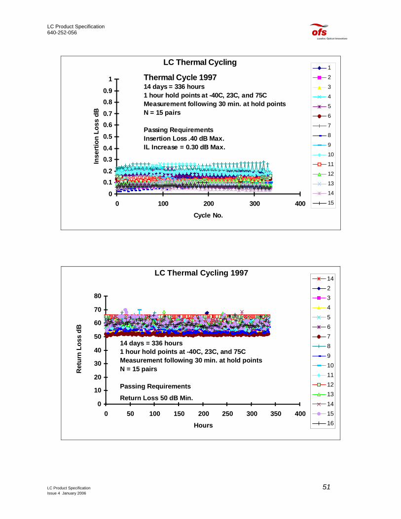
LC Thermal Cycling
0
0.10.2
0.30.4
0.5
0.60.7
0.80.9
1
0 100 200 300 400
Cycle No.
Inse
rtio
n Lo
ss d
B
1
2
3
4
5
6
7
8
9
10
11
12
13
14
15
Thermal Cycle 199714 days = 336 hours1 hour hold points at -40C, 23C, and 75CMeasurement following 30 min. at hold pointsN = 15 pairs
Passing Requirements Insertion Loss .40 dB Max.IL Increase = 0.30 dB Max.
LC Thermal Cycling 1997
0
10
20
30
40
50
60
70
80
0 50 100 150 200 250 300 350 400
Hours
Ret
urn
Loss
dB
142345678910111213141516
14 days = 336 hours1 hour hold points at -40C, 23C, and 75CMeasurement following 30 min. at hold pointsN = 15 pairs
Passing Requirements
Return Loss 50 dB Min.
LC Product Specification 51 Issue 4 January 2006