Embed Size (px)
Citation preview
Laying instruction:
speed•pipe®-indoor
Publisher
gabo Systemtechnik GmbH
Am Schaidweg 7
94559 Niederwinkling
GERMANY
Tel. +49 9962 950-200
Fax +49 9962 950-202
www.gabocom.com
Business division gabocom
Author: Martin Ziermann; 23.11.2017
Approval: Markus Karl; 24.11.2017
Edition 4
The current version of this laying instruction is available in the download area ”publication” under
www.gabocom.com.
After leaving gabo Systemtechnik this document is not subject to be changed.
No responsibility is taken for the correctness, timeliness and completeness of details and information. This document can be revised and
completed without prior notice. Liability for damages is excluded.
Table of Contents
1. General........................................................................................................................................ 3
2. Utilisation of speedpipe-indoor ................................................................................................... 4
3. Installation and instructions ......................................................................................................... 5
3.1 Installation according to DIN VDE 0100-520 :2013-06 / IEC 60364-5-52 :2009-10 ................ 5
3.2 Bending radius ....................................................................................................................... 6
3.3 Tensile forces ........................................................................................................................ 6
3.4 Cutting speedpipe indoor ....................................................................................................... 6 4. Firewall ........................................................................................................................................ 7
5. Blowing in of microcables / minicables / bundle fibers ............................................................... 9
6. Pictures from building site ..........................................................................................................14
3
1. General
The speedpipe-indoor must be protected against contamination and mechanical damage during
transport, storage and processing.
Any damage and deformation of the speedpipe-indoor (e.g. ovalisation) must be avoided and
cause a decrease in the blowing distance of the micro cables.
The speedpipe-indoor-ends must be protected against the penetration of dirt and water by means
of dust covers (protection against dust, dirt and splashing water, not pressure-tight), end plugs
ES indoor (pressure-tight up to 0.5 bar) or sealing elements EZA-t indoor (pressure-tight up to 0.5
bar).
When storing them over a long period of time (several months) the speedpipe-indoor must be
protected against direct solar radiation. In principle avoid outdoor storage.
It is impossible to make a general statement about the functional integrity of the speedpipe-indoor,
because the dimension of the particular speedpipe-indoor as well as the related cable must be
individually checked in combination.
The laying instructions are significant for the realisation of the construction and installation work.
4
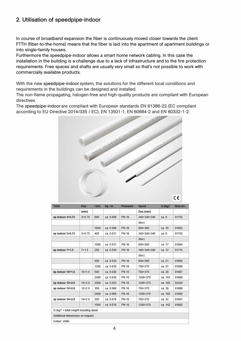
2. Utilisation of speedpipe-indoor
In course of broadband expansion the fiber is continuously moved closer towards the client.
FTTH (fiber-to-the-home) means that the fiber is laid into the apartment of apartment buildings or
into single-family houses.
Furthermore the speedpipe-indoor allows a smart home network cabling. In this case the
installation in the building is a challenge due to a lack of infrastructure and to the fire protection
requirements. Free spaces and shafts are usually very small so that’s not possible to work with
commercially available products.
With the new speedpipe-indoor system, the solutions for the different local conditions and
requirements in the buildings can be designed and installed.
The non-flame propagating, halogen-free and high-quality products are compliant with European
directives.
The speedpipe-indoor are compliant with European standards EN 61386-22 (EC compliant
according to EU Directive 2014/335 / EC), EN 13501-1, EN 60684-2 and EN 60332-1-2.
5
3. Installation and instructions
3.1 Installation according to DIN VDE 0100-520 :2013-06 / IEC 60364-5-52 :2009-10
All dimensions of speedpipe-indoor were tested in the VDE test institute according to DIN EN
61386-22.
Here, the mechanical strength values are taken from the table F.52.1 under point 521.6, which the
electrical installation pipes (speedpipe-indoor) must correspond to.
Essentially are the first four digits of the code, which reflect the following values by means of
defined tests:
- Compressive strength of the electrical installation pipes
- Impact strength of the electrical installation pipes
- Minimum operating temperature of the electrical installation pipes
- Maximum operating temperature of the electrical installation pipes
Further tests of the electrical installation pipes (speedpipe-indoor) are, for example, the resistance
to bending, the tensile strength, the load capacity, the electrical properties, resistance to external
influences and resistance to flame spread.
The mechanical strengths are classified from positions 1 - 4 (5), whereby 1 is the lowest
classification – for example “very low” - and 4 (5) is the highest classification – for example "very
high".
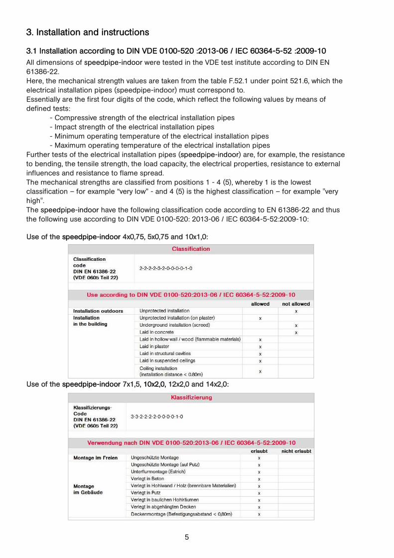
The speedpipe-indoor have the following classification code according to EN 61386-22 and thus
the following use according to DIN VDE 0100-520: 2013-06 / IEC 60364-5-52:2009-10:
Use of the speedpipe-indoor 4x0,75, 5x0,75 and 10x1,0:
Use of the speedpipe-indoor 7x1,5, 10x2,0, 12x2,0 and 14x2,0:
6
3.2 Bending radius
The minimum bending radius for speedpipe-indoor is 10x the outer-Ø
(e.g. speedpipe-indoor 7x1.5 = 70mm minimum bending radius).
Note: In a bending radius, connection sleeves must be avoided, as these can lead
to the stop of a blow-in operation, due to the inner edge of the open center
stop.
Recommendation: Always use the largest possible bending radius, as the best possible blow-in
performance is to be expected. Minimize the number of bending radius.
3.3 Tensile forces
Max. recommended tensile force and tensile load of the speedpipe-indoor in N (at 20 ° C):
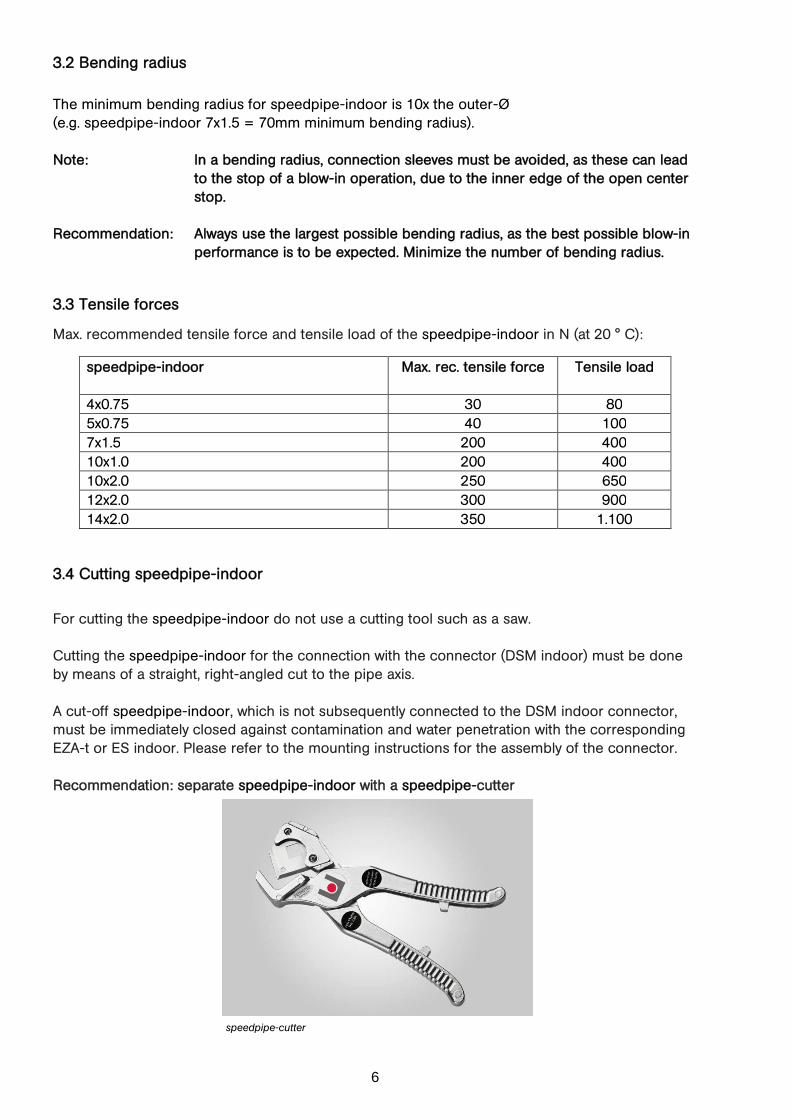
3.4 Cutting speedpipe-indoor
For cutting the speedpipe-indoor do not use a cutting tool such as a saw.
Cutting the speedpipe-indoor for the connection with the connector (DSM indoor) must be done
by means of a straight, right-angled cut to the pipe axis.
A cut-off speedpipe-indoor, which is not subsequently connected to the DSM indoor connector,
must be immediately closed against contamination and water penetration with the corresponding
EZA-t or ES indoor. Please refer to the mounting instructions for the assembly of the connector.
Recommendation: separate speedpipe-indoor with a speedpipe-cutter
speedpipe-cutter
speedpipe-indoor
Max. rec. tensile force
Tensile load
4x0.75 30 80
5x0.75 40 100
7x1.5 200 400
10x1.0 200 400
10x2.0 250 650
12x2.0 300 900
14x2.0 350 1.100

7
4. Firewall
Generally at the choice of the type of firewall please consider that the use of “pliable electrical
installation pipes according to DIN EN 61386-22” or the direct use of speedpipe-indoor must be
permitted in the respective AZB (General Technical Approval) or ETA (European Technical
Assessment). Furthermore in the ABZ / ETA the compliance of the pipe material (synthetic/plastic)
and the permitted pipe dimension must be observed.
For detailed information about the range of applications of the single firewalls, for example the
possibility of the performance with bundled speedpipe-indoor please contact the respective
manufacturer of the firewall, your expert for fire protection or your technical expert.

8
The examples at point are to show you various firewall manufacturers and their products. Thus is
to point out a certain range of manufacturers and products.
The listed firewall-types were checked in consultation with the relative manufacturer of the firewalls
for their applicability with speedpipe-indoor. There is no guarantee for the topicality of this
compatibility, because the above mentioned products and their approvals are not subject to the
responsibility of the company gabo Systemtechnik GmbH and furthermore also not to the
modification status. Therefore it is necessary to check and determine the compatibility with the
respective firewall manufacturers, with your fire safety engineer or your technical expert.
9
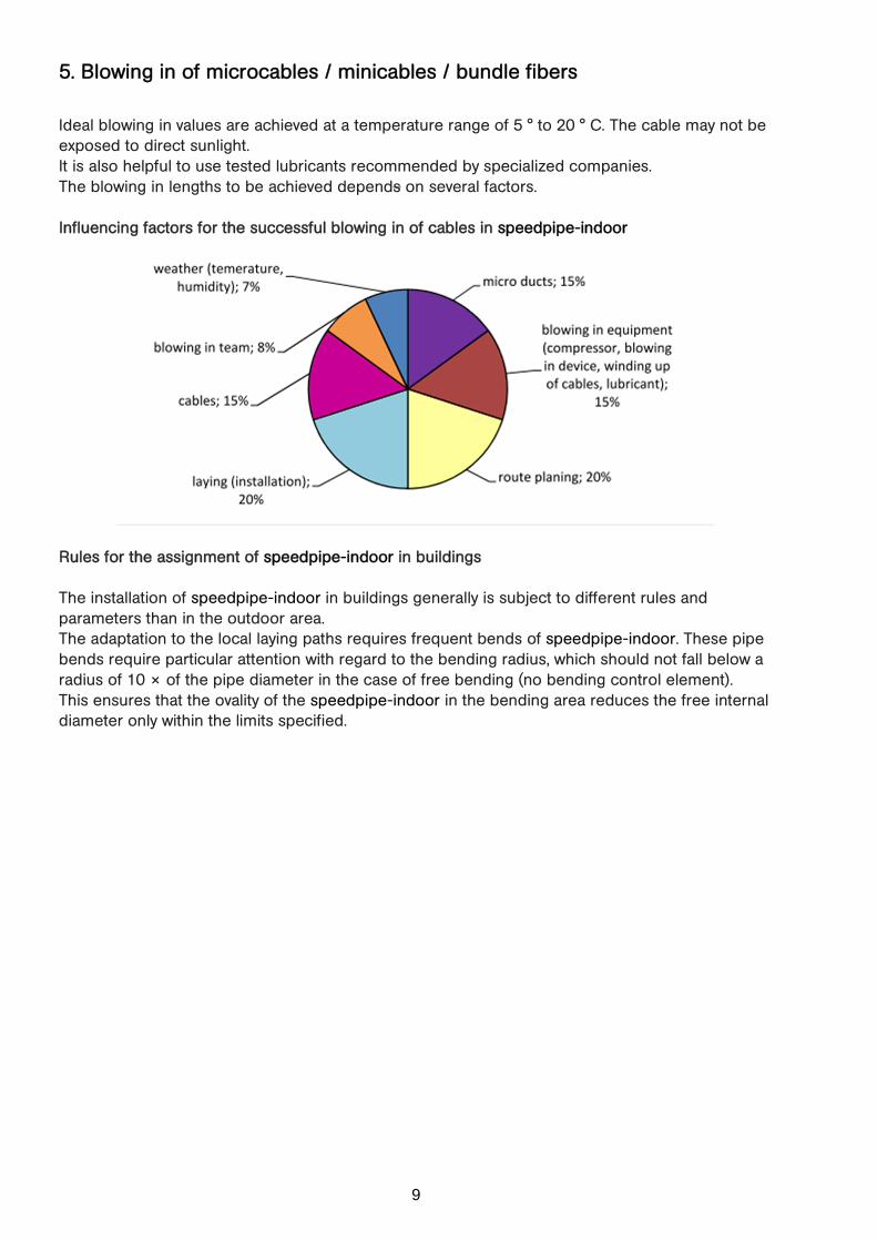
5. Blowing in of microcables / minicables / bundle fibers
Ideal blowing in values are achieved at a temperature range of 5 ° to 20 ° C. The cable may not be
exposed to direct sunlight.
It is also helpful to use tested lubricants recommended by specialized companies.
The blowing in lengths to be achieved depends on several factors.
Influencing factors for the successful blowing in of cables in speedpipe-indoor
Rules for the assignment of speedpipe-indoor in buildings
The installation of speedpipe-indoor in buildings generally is subject to different rules and
parameters than in the outdoor area.
The adaptation to the local laying paths requires frequent bends of speedpipe-indoor. These pipe
bends require particular attention with regard to the bending radius, which should not fall below a
radius of 10 × of the pipe diameter in the case of free bending (no bending control element).
This ensures that the ovality of the speedpipe-indoor in the bending area reduces the free internal
diameter only within the limits specified.
10
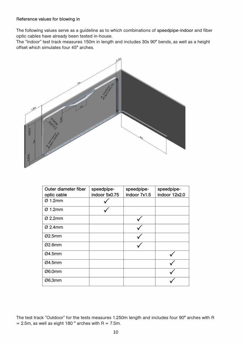
Reference values for blowing in
The following values serve as a guideline as to which combinations of speedpipe-indoor and fiber
optic cables have already been tested in-house.
The "Indoor" test track measures 150m in length and includes 30x 90° bends, as well as a height
offset which simulates four 45° arches.
Outer diameter fiber
optic cable
speedpipe-
indoor 5x0.75
speedpipe-
indoor 7x1.5
speedpipe-
indoor 12x2.0
Ø 1.2mm �
Ø 1.2mm �
Ø 2.2mm �
Ø 2.4mm �
Ø2.5mm �
Ø2.6mm �
Ø4.5mm �
Ø4.5mm �
Ø6.0mm �
Ø6.3mm �
The test track "Outdoor" for the tests measures 1.250m length and includes four 90° arches with R
= 2.5m, as well as eight 180 ° arches with R = 7.5m.

11
Outer diameter fiber
optic cable
speedpipe-
indoor 10x1.0
speedpipe-
indoor 12x2.0
Ø 6.3mm � �
12
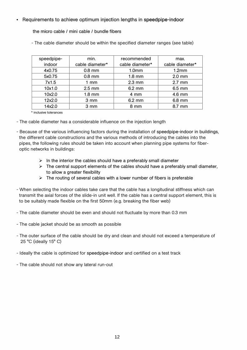
• Requirements to achieve optimum injection lengths in speedpipe-indoor
the micro cable / mini cable / bundle fibers
- The cable diameter should be within the specified diameter ranges (see table)
* inclusive tolerances
- The cable diameter has a considerable influence on the injection length
- Because of the various influencing factors during the installation of speedpipe-indoor in buildings,
the different cable constructions and the various methods of introducing the cables into the
pipes, the following rules should be taken into account when planning pipe systems for fiber-
optic networks in buildings:
� In the interior the cables should have a preferably small diameter
� The central support elements of the cables should have a preferably small diameter,
to allow a greater flexibility
� The routing of several cables with a lower number of fibers is preferable
- When selecting the indoor cables take care that the cable has a longitudinal stiffness which can
transmit the axial forces of the slide-in unit well. If the cable has a central support element, this is
to be suitably made flexible on the first 50mm (e.g. breaking the fiber web)
- The cable diameter should be even and should not fluctuate by more than 0.3 mm
- The cable jacket should be as smooth as possible
- The outer surface of the cable should be dry and clean and should not exceed a temperature of
25 °C (ideally 15° C)
- Ideally the cable is optimized for speedpipe-indoor and certified on a test track
- The cable should not show any lateral run-out
speedpipe-
indoor
min.
cable diameter*
recommended
cable diameter*
max.
cable diameter*
4x0.75 0.8 mm 1.0mm 1.2mm
5x0.75 0.8 mm 1.8 mm 2.0 mm
7x1.5 1 mm 2.3 mm 2.7 mm
10x1.0 2.5 mm 6.2 mm 6.5 mm
10x2.0 1.8 mm 4 mm 4.6 mm
12x2.0 3 mm 6.2 mm 6.8 mm
14x2.0 3 mm 8 mm 8.7 mm

13
• Blowing in of micro cable / minicable / bundle fibers
- The coil of the cable must be easily rotatable
- Ensure that the coil can be braked immediately in case of an unexpected stop
- Ensure the cable is clean
- Clean the speedpipe-indoor (inside) with a clean cylindrical sponge
- Use a suitable blow-in device (for example, Vetter)
- Use a compressor with a strong airflow, with max. pressure of 15 bar (1 m3 air volume for
speedpipe-indoor to inside diameter 12mm)
- The air from the compressor should be clean, oil-free, dried and cooled down with an aftercooler
to a temperature that is 8°C to 10°C higher than the ambient temperature
- The maximum blowing in speed should be limited to 80 m / min
- A cable guide head should be installed at the cable tip
• Lubricant
- Use suitable lubricant (e.g. Vetter)
- Pay attention to correct dosage according to manufacturer's instructions
- Spread the lubricant in the speedpipe by means of a cylindrical sponge before blowing in the
cable

14
6. Pictures from building site
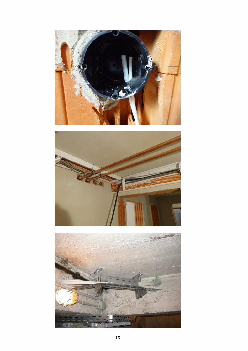
15


![j n Õ ( Ð 2 2 è! I ' #Ó Ñ¡2 !] f ! ] f ! ! ¡ ! Õ 20_(6790)_09092014.pdf · This IS 732 ± Part1 is based on IEC 60364 series namely IEC 6036 4 ± 1, 60364-4, 60364-5 & 60364-6](https://img.pdfslide.us/doc/110x75/5a73db587f8b9aea3e8b83b0/j-n-a-a-2-2-a-i-a-aa2-f-f-a-a-206790.jpg)