Embed Size (px)
Citation preview

.^FO^O^RiCU^USE ONLY
Laying Cable in theForward Area
{Confidential)
7*./-f:
Signal Corps, U. S. Army7-27-18
Genera
ted o
n 2
01
5-1
1-0
1 0
6:4
6 G
MT /
htt
p:/
/hd
l.hand
le.n
et/
20
27
/nyp.3
34
33
02
04
62
63
0Public
Dom
ain
, G
oog
le-d
igit
ized
/
htt
p:/
/ww
w.h
ath
itru
st.o
rg/a
ccess
_use
#pd-g
oogle
Laying Cable in the Forward Area
Genera
ted o
n 2
01
5-1
1-0
1 0
6:4
7 G
MT /
htt
p:/
/hd
l.hand
le.n
et/
20
27
/nyp.3
34
33
02
04
62
63
0Public
Dom
ain
, G
oog
le-d
igit
ized
/
htt
p:/
/ww
w.h
ath
itru
st.o
rg/a
ccess
_use
#pd-g
oogle
Table of ContentsPage
installing Underground Cable 3
Assignment of Pairs 4
Two-Man Method 5
One-Man Method 6
Splicing Lead-Covered Paper insulated Cable 7
Planning the Splice S
Stripping and Boiling Out 8
Wrapping the Splice 11
Splicing Ferrin Cable 12
Determining the Nature of Cable Trouble 12
Short 13
Ground HCross 14
Split Pairs 15
Open Pair 15
Locating Cable Troubles 16
Varley Loop Test 16
Murray Loop Test 17
Locating Ground with One Bad Wire of KnownLength and Two Good Wires of Unknown Length. 17
Locating Ground with All Wires Bad 19
Locating an Open 20
Locating a Split Pair 21
Locating a Short 22
Precautions in Handling Cable 22
Genera
ted o
n 2
01
5-1
1-0
1 0
6:4
8 G
MT /
htt
p:/
/hd
l.hand
le.n
et/
20
27
/nyp.3
34
33
02
04
62
63
0Public
Dom
ain
, G
oog
le-d
igit
ized
/
htt
p:/
/ww
w.h
ath
itru
st.o
rg/a
ccess
_use
#pd-g
oogle
LAYING CABLE IN THE FORWARD AREA
INa large part of the wire communication systems from thefront positions back over a distance of three to five miles,
extensive use is made of underground cable consisting of
a number of pairs of wires insulated with paper and covered
with a lead sheath, which can be used for telephone, telegraph, buzzerphone, etc., work. The route to be followed forsuch cable runs, and the size of cable (number of pairs of
wire) to be laid is determined by the corps or division signalofficer. As a rule, not less than 20 pairs are laid in one
trench.
Installing Underground Cable
Trenches for laying the cable are dug to a depth of from6 ft. to 15 ft., depending on the location and importance of
the run, and 24 in. to 36 in. wide. The smaller sizes of cable
are received wound on reels in 1000-ft. lengths. When the
cable is laid, the reels are jacked up on a shaft to rotateeasily and the cable pulled from them. On long runs the
cable is usually laid in 1000-ft. lengths between splicing points.
Before the cable is laid a layer of sand or screening at
least 3 in. deep should be put in the bottom of the trench
to facilitate drainage. The cable should be laid with someslack, so that it will more readily withstand heavy vibrationcaused by shell fire. In burying the cable, if possible, it is
best to cover it with b-ush and then fill in with soil. Thiswill act as a cushion and give considerable protection against
the destructive shells. In laying and covering the cables,
utmost care should be exercised to avoid injury to the lead
sheath. Particular precaution should be taken to avoid kinking the cable, as this is very likely to make a crack in the
lead into which moisture will creep and cause cross talk orshort circuits. Care must also be taken to protect the cablesfrom all electrical injury. Where aerial lines join an underground cable a lightning arrester should be installed on thelast pole. Telephone stations connected directly to underground cable without any intervening aerial wire or cable
do not need to have any lightning protection.
3 S
Genera
ted o
n 2
01
5-1
1-0
1 0
6:4
8 G
MT /
htt
p:/
/hd
l.hand
le.n
et/
20
27
/nyp.3
34
33
02
04
62
63
0Public
Dom
ain
, G
oog
le-d
igit
ized
/
htt
p:/
/ww
w.h
ath
itru
st.o
rg/a
ccess
_use
#pd-g
oogle
4
At least every 3000 ft. In a cable run, manholes or testing stations should be installed, the approximate dimensionsof the manholes being 6 ft. long x 3% ft. wide x whateverdepth Is needed to give the necessary head room and installthe roof protection. The long way of the manhole should be
parallel to the line of the cable run. The construction ofthese manholes will of course be governed by the conditionsmet with, but where possible the ceiling should be 2 ft.below the surface of the surrounding ground and covered withcorrugated sheet iron, at least two layers of sand in bags, 6
in. of reinforced concrete blocks, and at least 3 ft. ofearth on top, and the fresh soil covered with a brush camouflage. Steps from the surface should be installed to lead intothe manhole at one end, the long sides being kept clear forracking the cable in an orderly manner to facilitate splicing,testing, etc. A manhole is used as a test station, as a pointfrom which to take off branch cables to aerial lines, as a
place to cross-connect and reroute pairs, to lead off twistedpair lines, etc. In case of injury to the cable, or a breakdown between two manholes, twisted pair sometimes may betemporarily run between the two manholes until repairs can
be made. To facilitate repair in this manner it is thereforedesirable to have manholes as frequently as practicable withthe cost in mind.
Greatest care must be taken when working with paper insulated cable to prevent moisture from getting into it. Thepresence of the slightest dampness seriously impairs thetransmission of communications through the cable, makingit necessary to promptly locate the leak, open up the sheath,boil out the cable with paraffin and close up the opening witha standard splice. The longer the delay In removing a badplace in a cable, the farther the moisture creeps in, it some
times being necessary to cut out several feet and splice in a
new section of cable. The method of locating such faults is
taken up in a later section.
In all the lead-covered cables used for Signal Corps purposes the wire conductors are twisted in pairs, so that in a
cable having 20 pairs of wires there are 20 separate, directtelephone or telegraph two-wire circuits. In all Gases the twowires are wrapped in different colored paper, usually one red.
Genera
ted o
n 2
01
5-1
1-0
1 0
6:4
8 G
MT /
htt
p:/
/hd
l.hand
le.n
et/
20
27
/nyp.3
34
33
02
04
62
63
0Public
Dom
ain
, G
oog
le-d
igit
ized
/
htt
p:/
/ww
w.h
ath
itru
st.o
rg/a
ccess
_use
#pd-g
oogle
5
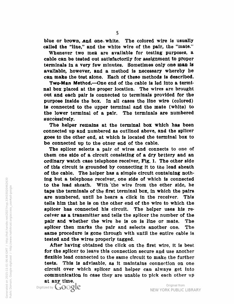
blue or brown, .and one- white. The colored wire is usually
called the "line," and the white wire of the pair, the "mate."
Whenever two men are available for testing purposes, a
cable can be tested out satisfactorily for assignment to proper
terminals in a very few minutes. Sometimes only one man isavailable, however, and a method is necessary whereby he
can make the test alone. Each of these methods is described.
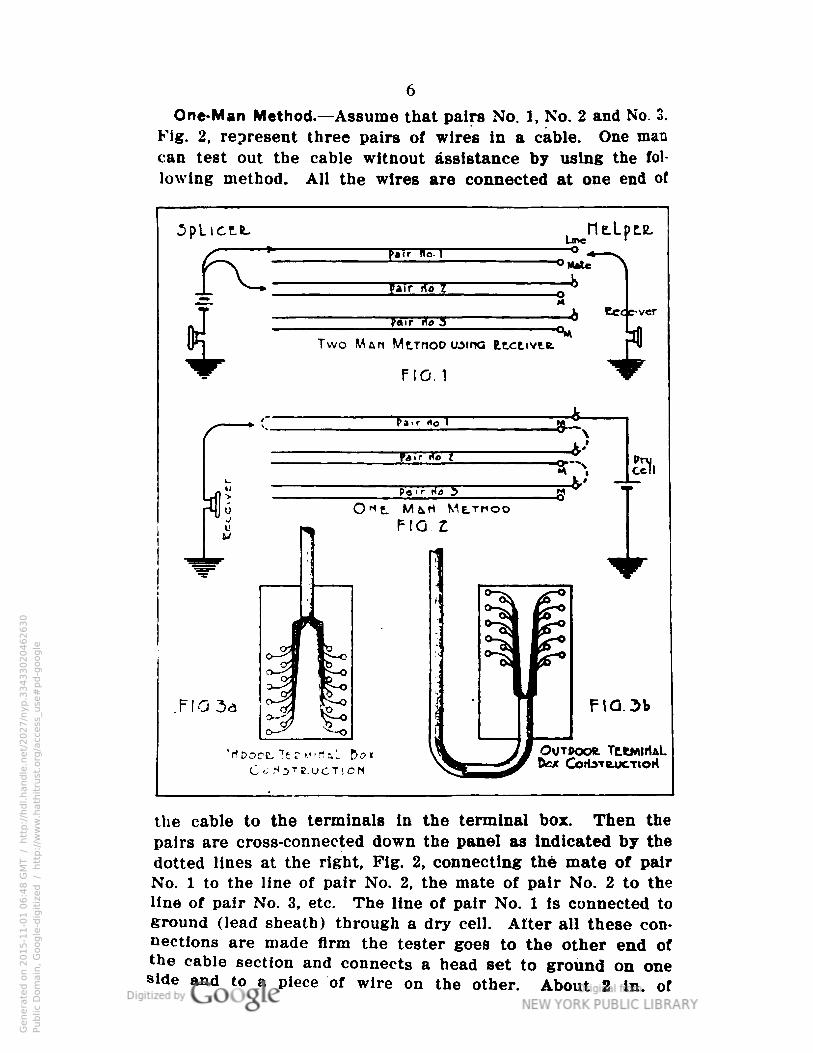
Two-Man Method. —One end of the cable is led Into a terminal box placed at the proper location. The wires are brought
out and each pair Is connected to terminals provided for thepurpose inside the box. In all cases the line wire (colored)is connected to the upper terminal and the mate (white) to
the lower terminal of a pair. The terminals are numberedsuccessively.
The helper remains at the terminal box which has beenconnected up and numbered as outlined above, and the splicergoes to the other end, at which Is located the terminal box to
be connected up to the otner end of the cable.
The splicer selects a pair of wires and connects to one of
them one side of a circuit consisting of a dry battery and anordinary watch case telephone receiver, Fig. 1. The other side
of this circuit is grounded by connecting it to the lead sheath
of the cable. The helper has a simple circuit containing nothing but a telephone receiver, one side of which is connectedto the lead sheath. With 'the wire from the other side, he
taps the terminals of the first terminal box, in which the pairsare numbered, until he hears a click in the receiver. Thistells him that he is on the other end of the wire to which thesplicer has connected his circuit. The helper uses his re
ceiver as a transmitter and tells the splicer the number of thepair and whether the wire he is on is line or mate. Thesplicer then marks the pair and selects another one. Thesame procedure is gone through with until the entire cable istested and the wires properly tagged.
After having obtained the click on the first wire, it is bestfor the splicer to leave this connection secure and use anotherflexible lead connected to the same circuit to make the furthertests. This is advisable, as it maintains connection on onecircuit over which splicer and helper can always get into
communication in case they are unable to pick each other up
at any time.
Genera
ted o
n 2
01
5-1
1-0
1 0
6:4
8 G
MT /
htt
p:/
/hd
l.hand
le.n
et/
20
27
/nyp.3
34
33
02
04
62
63
0Public
Dom
ain
, G
oog
le-d
igit
ized
/
htt
p:/
/ww
w.h
ath
itru
st.o
rg/a
ccess
_use
#pd-g
oogle
6
One-Man Method. —Assume that pairs No. 1, No. 2 and No. 3,
Fig. 2, represent three pairs of wires in a cable. One man
can test out the cable witnout assistance by using the fol
lowing method. All the wires are connected at one end of
the cable to the terminals in the terminal box. Then the
pairs are cross-connected down the panel as indicated by the
dotted lines at the right, Fig. 2, connecting the mate of pairNo. 1 to the line of pair No. 2, the mate of pair No. 2 to the
line of pair No. 3. etc. The line of pair No. 1 is connected toground (lead sheath) through a dry cell. After all these connections are made firm the tester goes to the other end ofthe cable section and connects a head set to ground on oneside and to a piece of wire on the other. About 2 in. of
Genera
ted o
n 2
01
5-1
1-0
1 0
6:4
8 G
MT /
htt
p:/
/hd
l.hand
le.n
et/
20
27
/nyp.3
34
33
02
04
62
63
0Public
Dom
ain
, G
oog
le-d
igit
ized
/
htt
p:/
/ww
w.h
ath
itru
st.o
rg/a
ccess
_use
#pd-g
oogle
7
the paper insulation is skinned off at the ends of the wires.The ends are then touched with the free receiver connectionuntil a wire is found which causes a click in the receiver.This will identify that wire as the line wire of pair No. 1,
since this is the only circuit through the battery at the farend. This wire is twisted lightly with its mate (just enoughto make an electrical contact) and is marked "Pair No. l
with some sort of tag. The two ends of pair No. 1 are thusconnected as shown by the dotted line at the left of Fig. 2.
Next, the tester begins touching the other wire ends with thereceiver contact wire until ar.ouier click is obtained. Thiswire must be the line wire of pair No. 2, as will be seen bytracing out the circuit, Fig. 2. This wire is connected to itsmate and tagged "No. 2." The test is repeated until all thepairs of the cable are identified. The wires are then permanentlyconnected in the terminal box in their proper order. To clearthe lines, the temporary connections between pairs whichwere made at the beginning of the test are removed from the
first terminal box.From the above it is seen that the main object in testing
out cables newly installed is to identify the various pairs so
that they may be given the same numbers at all terminals, as
this greatly expedites assignment of pairs and location of
trouble.On installations inside of buildings the cable may be
brought into a terminal box at the top or bottom, whichevergives the most direct route, Fig. 3-a. At all outside terminalboxes or at boxes installed in dugouts, the cable must be
brought into the bottom of the terminal box so that the waterrunning down the cable will drip off below the box and notget into the exposed wiring, Fig. 3-b.
Splicing of Lead Covered Paper Insulated Cable.
Cables and communicating systems installed near the frontare constructed with no great aim toward permanency. Thelife of any cable system in the area subjected to heavy shelling is not long, and the standard construction methods are
therefore abandoned in favor of a temporary constructionwhich serves the purpose just as well. The following instructions cover the method of making splices on the small, for
Genera
ted o
n 2
01
5-1
1-0
1 0
7:0
9 G
MT /
htt
p:/
/hd
l.hand
le.n
et/
20
27
/nyp.3
34
33
02
04
62
63
0Public
Dom
ain
, G
oog
le-d
igit
ized
/
htt
p:/
/ww
w.h
ath
itru
st.o
rg/a
ccess
_use
#pd-g
oogle
8
ward cables and they should not be used to govern work onthe more permanent cable systems farther back.
Materials Required. Tools Required.Paper sleeves PliersParaffin Cable kalfeRolls of muslin strip Hammer, clawRubber tape Paraffin kettleFriction tape DipperInsulating compound Gasoline furnaceWooden splice box Compound kettleNails (\y2 doz. 10-penny) Blow torchGasoline
Planning the Splice. —The lead sheath should not be opened
until ready to work on the wires and all the necessary material is at hand. The longer a cable is open to the atmosphere,the more likely it is to absorb moisture with resulting badoperation. The length of time a cable is open should be made
the minimum possible, and it should never be left open overnight without being thoroughly wrapped with muslin and rubber tape and boiled out next morning when re-opened. Whenever a piece of cable is cut off a reel, both ends thus exposedmust be sealed immediately with solder to keep out themoisture.
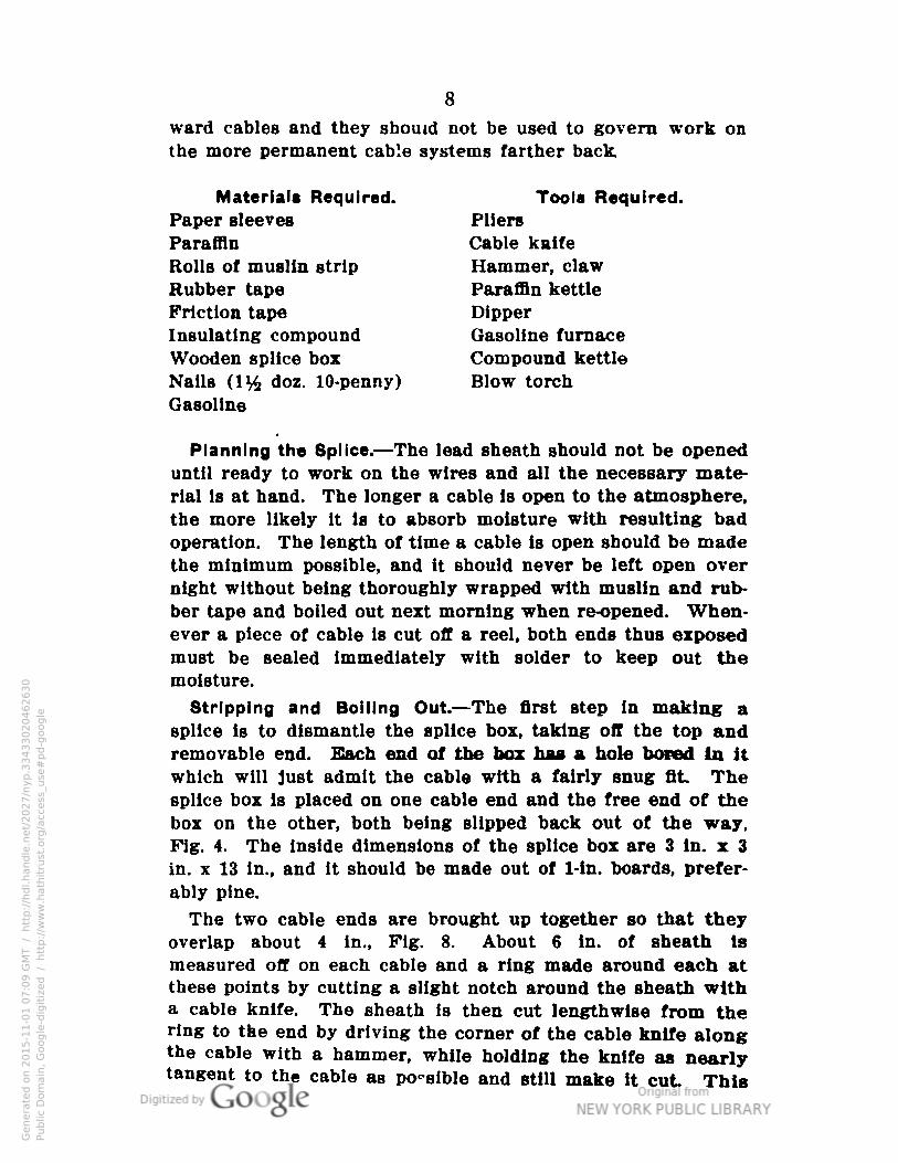
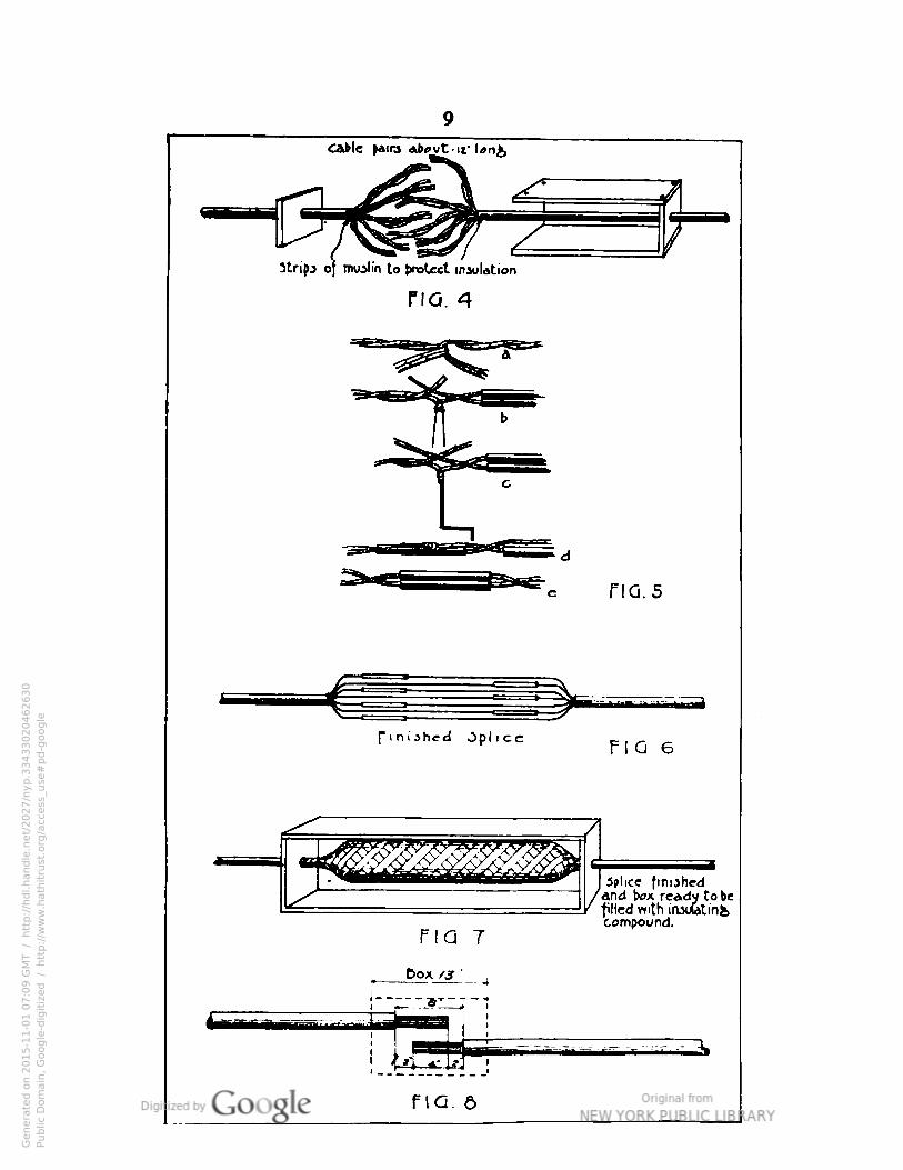
Stripping and Boiling Out. —The first step in making asplice is to dismantle the splice box, taking off the top andremovable end. Each end of the box has a hole bored In itwhich will Just admit the cable with a fairly snug fit. Thesplice box is placed on one cable end and the free end of thebox on the other, both being slipped back out of the way.Fig. 4. The inside dimensions of the splice box are 3 in. x 3
in. x 13 in., and it should be made out of 1-in. boards, preferably pine.
The two cable ends are brought up together so that theyoverlap about 4 in., Fig. 8. About 6 in. of sheath Ismeasured off on each cable and a ring made around each atthese points by cutting a slight notch around the sheath witha cable knife. The sheath is then cut lengthwise from thering to the end by driving the corner of the cable knife alongthe cable with a hammer, while holding the knife as nearlytangent to the cable as po-sible and still make it cut. This
Genera
ted o
n 2
01
5-1
1-0
1 0
7:0
9 G
MT /
htt
p:/
/hd
l.hand
le.n
et/
20
27
/nyp.3
34
33
02
04
62
63
0Public
Dom
ain
, G
oog
le-d
igit
ized
/
htt
p:/
/ww
w.h
ath
itru
st.o
rg/a
ccess
_use
#pd-g
oogle
9
cable faira «fc»vt.ir l*n&
Strips o] muslin to J1roUct insulation
no. 4
flQ.5
finished OpficcFl O. 6
^v^^-v:-.:->-.,-f:,:^:
na. 7
Dox /J "
. spbce finishedand box rcAdv to tie
filled with iniuatinfecompound.
no. e
Genera
ted o
n 2
01
5-1
1-0
1 0
7:0
9 G
MT /
htt
p:/
/hd
l.hand
le.n
et/
20
27
/nyp.3
34
33
02
04
62
63
0Public
Dom
ain
, G
oog
le-d
igit
ized
/
htt
p:/
/ww
w.h
ath
itru
st.o
rg/a
ccess
_use
#pd-g
oogle
10
will avoid cutting the paper insulation. Alter the sheath is
thus cut open it is pulled back each way around the cable
with the claws of the hammer and broken off at the ring.When completed the splice should be something less than 13
inches long over all, so that it v. ill be easily enclosed by the
13-in. splice box.
When the sheath is removed, the cable core should be
served at the edges of the sheath with several wrappings ofmuslin. The paper wrapping is then removed from the core
and hot paraffin poured over the muslin and open wire to
assist in keeping the moisture out while the joint is open.
The muslin will prevent the sheath from injuring the insulation of the wires when tl-ey are bent back preparatory tosplicing. The paraffin should always be poured from thesheath toward the center of the splice. This tends to driveany moisture toward the center of the opening rather thanback into the sheath. The temperature of paraffin should be
above tnat of boiling water (212 deg. F.), but not hot enough
to scorch the paper insulation. If the temperature is nothigher than that of boiling water, the moisture will not bedriven out. A common and effective test is to expectorate inthe paraffin. If a considerable sputtering results, the paraffinis hot enough. If the paraffin is allowed to become too hot, itwill catch Are on the surface very readily, so that this may beused as an indication of overheating. This "boiling out" ofcable is absolutely essential and must be carefully done andnever omitted. If not done properly, a faulty splice willdevelop.
After boiling out, the wires of each pair are twisted togethertightly, so that no "split pairs" will result. This is very important. The conductors are now bent back over the sheathout of the way. Starting with the far layer of pairs, a pairof wires from each cable end which have approximately thecorresponding positions in the cables are brought together,Pig. 5-a. The ends of the two wires of one pair are untwisted and a paper sleeve slipped over each wire of thatpair and pushed back out of the way. The two line wires arebrought together, allowing some slack, and given two or threetwists, Pig. 5-b. The mates are then brought together in thesame manner. The ends of both are cut off about 2 in.from the twist and the insulating paper removed up to the-vist. The bare ends of the two line wires are now bent into
Genera
ted o
n 2
01
5-1
1-0
1 0
7:0
9 G
MT /
htt
p:/
/hd
l.hand
le.n
et/
20
27
/nyp.3
34
33
02
04
62
63
0Public
Dom
ain
, G
oog
le-d
igit
ized
/
htt
p:/
/ww
w.h
ath
itru
st.o
rg/a
ccess
_use
#pd-g
oogle
11
a crank handle, Fig. 5-c, and the two ends wound up untilthere Is about 1 In. of tight twist, having at least 10 half-
turns. The ends are cut off below the twist and the twistedportion bent over against and parallel to the insulated portion,Fig. 5-d. The operation is repeated with mate ends. Thepaper sleeves are then slipped up over the bare twists and
the two wires of each pair given a few twists about each otherto hold them together and keep the paper sleeves in place,Fig. 5-e.
In bringing successive pairs together for splicing, the loca
tions of the twists should be staggered to distribute along thesplice the bulkiness of the paper sleeves, Fig. 6. Before usingthe paper sleeves they must always be thoroughly boiled outin hot paraffin and then allowed to drain and cool.
The above "crank-handle method" of splicing can be usedsatisfactorily only on the smaller sizes of wire, such as Nos
19 and 22 gauge, which are the sizes most commonly employed.
Where larger than No. 16 gauge wire is encountered, it willbe necessary to use copper sleeves and solder instead of a
twisted connection.Wrapping the Splice. —After the wires are all spliced, mus
lin strips are wrapped closely around the splice. The spliceis then thoroughly saturated with hot paraffin to remove anypossible moisture present before closing up the joint. Theparaffin is then carefully cleaned off the lead sheath and tworeversed layers of rubber tape tightly wrapped around themuslin and extended onto the sheath for a distance of 1%in. at each end of the splice. Over the rubber tape twolayers of friction tape are wound and extended onto thesheath for a length of y2 in. beyond the rubber tape. Thetape must be wrapped particularly tight at both ends to insurea water-tight joint. Care must be taken that the taping is notextended over the sheath for too great a length, as this wouldcause the splice to buckle in the splice box when this wasclosed.
The box Is now assembled around the splice and the unattached end nailed in place, Fig. 7. The box is then filled withvery hot insulating compound and the top nailed on. The boxmust not be disturbed while the compound is cooling, or theseal which it provides will be broken. The effect of this hotcompound is not only to seal the joint when it sets, but also,
by virtue of its temperature, to actually vulcanize the rubber
tape, friction tape and muslin into a unit water-proof covering.
Genera
ted o
n 2
01
5-1
1-0
1 0
7:0
9 G
MT /
htt
p:/
/hd
l.hand
le.n
et/
20
27
/nyp.3
34
33
02
04
62
63
0Public
Dom
ain
, G
oog
le-d
igit
ized
/
htt
p:/
/ww
w.h
ath
itru
st.o
rg/a
ccess
_use
#pd-g
oogle
12
Splicing Ferrin Cable
Where less than a 10-pair cable is needed, It is now quitegeneral practice with the American Expeditionary Forces to
make use of Ferrin cable, commonly called "loom" cable. Thisconsists of a tar, cloth and rubber casing enclosing rubbercovered wire twisted in pairs. The manner of splicing is
quite different from that employed with lead covered cable.
The covering at the two ends of the cable is cut open along the
cable as short a distance back from the end as possible andgive sufficient length of wire to make the splice (approximately 6 in. on each end). About 2 in. of insulation is
scraped off on each wire and the proper wires twisted together, using the Western Union joint and taking specialprecaution to make the length of each wire between cablesheath ends uniform. This is important in order that any
strain on the cable will be borne equally by all wires, as theopened sheath will not take up the strain. If practicable, eachjoint should be soldered, but if solder is not available, a layerof tinfoil or paper should be placed over the bare joint beforeit is wrapped with the rubber tape. This will prevent oxidation of the copper due to the action of the rubber, whichwould take place if there were no protection. The joint isthen heated with a candle or other flame and moulded slightlywith the fingers to partially vulcanize the rubber and seal the
insulation.
After all the wires are treated in this manner, the split endsof the sheath are put back in place, cutting them to fit together as snugly as possible around the core. A double layerof friction tape is wrapped over the sheath, after which two
reverse layers of rubber tape are applied. This taping isheated to vulcanize and form it into a unit insulation and thenserved with two or three layers of friction tape for protection.
Determining the Nature of Cable Trouble
In splicing cable, any one of the following troubles mayoccur: short, ground, cross, split pairs or open pairs. Allthese faults except split pairs are sometimes found in thecable upon receipt from the manufacturer, but this is rare asthe cable is tested before being shipped. The methods oftesting given in the following paragraphs are intended pri
Genera
ted o
n 2
01
5-1
1-0
1 0
7:0
9 G
MT /
htt
p:/
/hd
l.hand
le.n
et/
20
27
/nyp.3
34
33
02
04
62
63
0Public
Dom
ain
, G
oog
le-d
igit
ized
/
htt
p:/
/ww
w.h
ath
itru
st.o
rg/a
ccess
_use
#pd-g
oogle

13
marily for use at the time the cable is installed before pairsare assigned and in use. Determining the nature of thesefaults after the cable is in use is simplified, as it is usuallyknown just which pair the trouble is in.
Short.—This trouble in a pair of wires means that, due tofaulty insulation, the two wires are short circuited and therefore cannot be used as a pair for communication purposes,Pig. 9. The illustration is of course exaggerated inasmuchas a shorted pair can result from a very small defect in the
insulation.
Insulation
> > > >
.Z.O S3
pLu Pail
Optrl
Fta II
Fig. iz
Na i!>
To test out a cable for shorts, a circuit consisting of anordinary watch case telephone receiver and a dry cell is con
nected successively across the wires of each pair of the
Genera
ted o
n 2
01
5-1
1-0
1 0
7:0
9 G
MT /
htt
p:/
/hd
l.hand
le.n
et/
20
27
/nyp.3
34
33
02
04
62
63
0Public
Dom
ain
, G
oog
le-d
igit
ized
/
htt
p:/
/ww
w.h
ath
itru
st.o
rg/a
ccess
_use
#pd-g
oogle
14
cable. If a click is heard in the receiver upon touching the
two ends of any pair, when it is known that that pair is open
at the opposite end of the cable, this signifies that there is a
short-circuit between the two wires. In long cable runs it is
possible that there will be enough static capacity to cause a
click even though the pair is not shorted. It is thereforebest to tap the test circuit connection to the wires of thepair several times, and if a click is heard after the first or
second tap, it is a certain indication that a short exists. Thissame precaution against static clicks must be observed inconnection with testing out for the troubles described in thefollowing paragraphs.
Ground, —A ground in a pair of wires in such a conditionas is shown in an exaggerated way in Fig. 10. In this case
one of the wires is grounded on the lead sheath of the cableor on some other grounded object inside the cable, and v, hi!?
the pair can be used for conversation, the transmission usually will be poor and there likely will be a scratching, sizzlingnoise in the receiver. In case both wires of a pair aregrounded, there exists the equivalent of a shorted pair, and
this pair cannot be used for communication purposes.To test out for a ground in any of the pairs of a cable the
same circuit referred to above is used, one side being connected to the ground or cable sheath and the other side to allof the wire ends in the cable successively. If a click is heardwhen connection is made to any wire, it signifies that thiswire is grounded, thereby completing the circuit through the
test circuit receiver.
Cross. —When pairs are crossed, conversation can be hadover either pair, but both cannot be used at the same time, as
both conversations will be heard over both pairs. A ring oneither pair will probably cause the signals of both at theexchange to drop. Both pairs will be noisy. An illustrationof crossed pairs is shown in Fig. 11.
To test a cable for crossed pairs, using the receiver anddry cell circuit, one side of the test circuit is connected successively to each of the wire ends of the entire cable, and foreach such connection the other side of the test circuit istouched to all other wire ends. As seen from Fig. 11, if across exists in the cable, one combination of interconnectionbetween pairs will form a circuit and a click will be heard inthe receiver. This will Identify the pairs in trouble, since if
Genera
ted o
n 2
01
5-1
1-0
1 0
7:1
0 G
MT /
htt
p:/
/hd
l.hand
le.n
et/
20
27
/nyp.3
34
33
02
04
62
63
0Public
Dom
ain
, G
oog
le-d
igit
ized
/
htt
p:/
/ww
w.h
ath
itru
st.o
rg/a
ccess
_use
#pd-g
oogle
15
all were perfect such a connection would give no click whatever.
Split Pairs. —This fault is caused by the splicer being careless in splicing the pairs together. A split pair practicallynever occurs in the cable traceable to any other cause thanthe work of the splicer. A split pair exists when the twowires of one pair are connected to one wire each of two opposite pairs. This fault defeats the purpose of the transpositions in the cable, which are made about every 3 in., and
results in cross talk. Fig. 12 illustrates a split pair in a cable.To test out for this trouble, two men are necessary. The
helper goes to the far end of the cable section and cross-connects the two wires of each pair. At the opposite end ofthe section the splicer connects one side of a test circuit,consisting of a receiver and a dry cell, to the line wire of
each pair successively, and for each such connection, touches
the other side of the test circuit to all the other wire ends
in the cable. If a split pair exists, one wire other than themate of the line wire to which the first side of the test circuitis connected will be found which will give a click in the
receiver. There will probably be two such combinations ofconnections, since if one pair is split, it will necessitate thesplitting of another pair in order to make the pairs come outeven.
Open Pair.— An open pair exists when one wire of a pair isbroken, Fig. 13. Such a pair cannot be used for communica
tion purposes. It can be used only as a one-wire grounded
line for emergency purposes.
The test for open pair is to use the same receiver and dry
cell circuit, and connect all terminals together at one end ofthe cable section. One receiver lead is then held on any
terminal at the opposite end of the section and the other sideof the test circuit touched to all other terminals. Any wirewhich does not give a click indicates an open circuit in thatwire.
General. —In making the tests as described above, a tonemachine or buzzer, or a magneto may be employed effectively.
When using the tone machine, a buzz will be heard by the
tester when the trouble is located, except when there is an
open. With the magneto, a bell may be used, or a receiver,
to designate the circuits in trouble. When a cable section has
Genera
ted o
n 2
01
5-1
1-0
1 0
7:1
0 G
MT /
htt
p:/
/hd
l.hand
le.n
et/
20
27
/nyp.3
34
33
02
04
62
63
0Public
Dom
ain
, G
oog
le-d
igit
ized
/
htt
p:/
/ww
w.h
ath
itru
st.o
rg/a
ccess
_use
#pd-g
oogle
16
been installed and connections made in both terminals, it
should be tested out forall the faults indicated above.
Locating Cable Troubles
After having determined the nature of the trouble in a pair
of wires by using any one or all of the foregoing methods, iithen becomes necessary to locate the exact point of the
trouble, so that it can be removed. An accurate method of
locating trouble is to use a Wheatstone bridge, which will
determine quite closely the distance out on a cable at which
the trouble exists, in terms of the resistance of the intervening
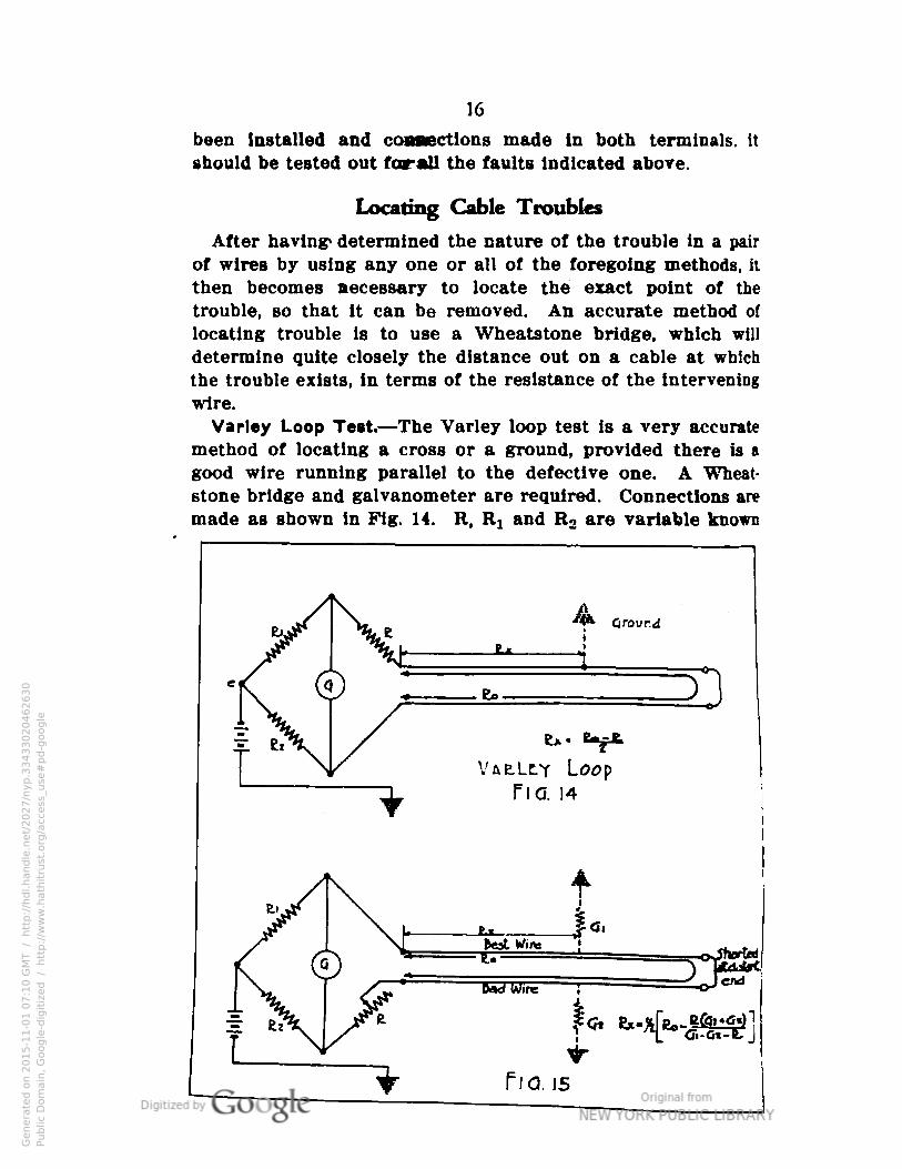
wire.Varley Loop Test.—The Varley loop test is a very accurate
method of locating a cross or a ground, provided there is a
good wire running parallel to the defective one. A Wheat-
stone bridge and galvanometer are required. Connections are
made as shown in Fig. 14. R, Rl and R2 are variable known
ha. 15
Genera
ted o
n 2
01
5-1
1-0
1 0
7:1
0 G
MT /
htt
p:/
/hd
l.hand
le.n
et/
20
27
/nyp.3
34
33
02
04
62
63
0Public
Dom
ain
, G
oog
le-d
igit
ized
/
htt
p:/
/ww
w.h
ath
itru
st.o
rg/a
ccess
_use
#pd-g
oogle
17
resistances. When Rj is made equal to R2, and R is adjusted
until no deflection of the galvanometer takes place, then thefollowing equation is true:
where Rx is the resistance out to the ground. R0 is the re
sistance of a complete loop consisting of the good wire andthe grounded wire, and R is the resistance of the bridge arm.
R0 can be obtained from standard wire tables if the size orresistance of the wire and distance between sections areknown. The distance to the ground may then be computedby dividing the resistance Rx by the resistance per foot as
obtained from the tables.
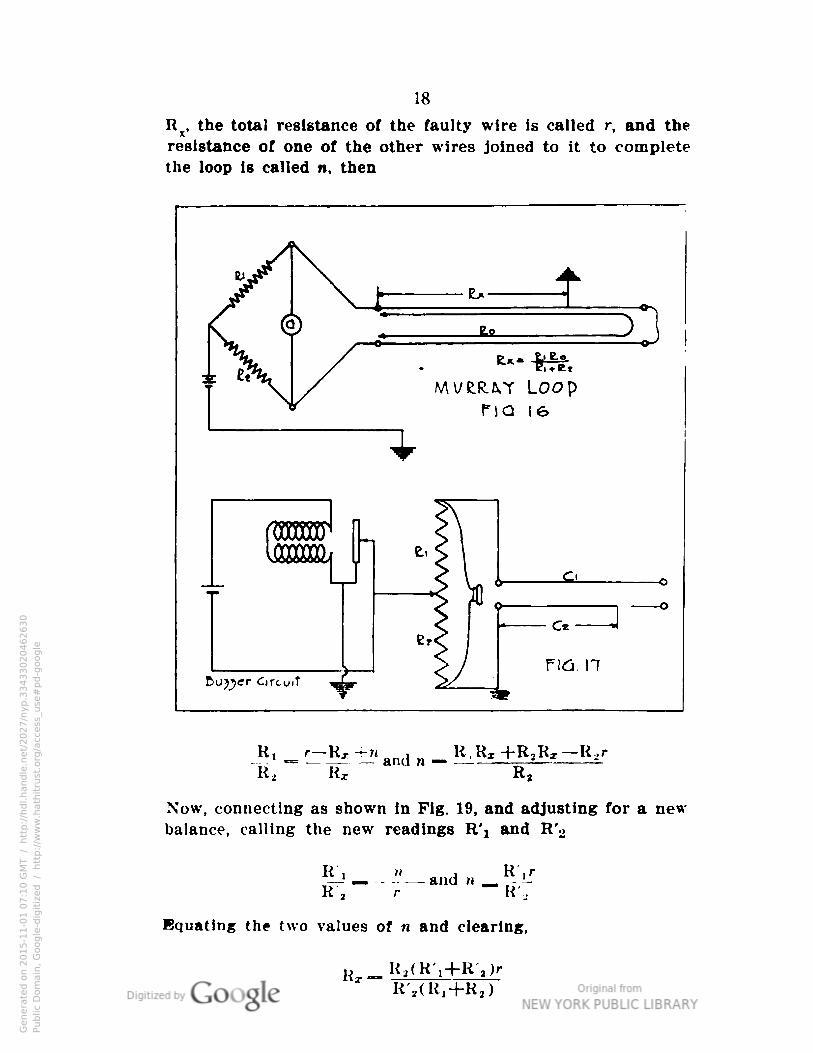
Murray Loop Test.—The Murray loop test is used when only
two bridge resistance arms and a galvanometer are available. Connections are made as in Fig. 16 and when Rj and
R2 are so adjusted that no denection of the galvanometer isnoted, the following equation may be solved to determine the
resistance of the bad wire out to the fault, from which the
distance to the fault can be computed as outlined in theVarley loop test:
* bTTr,
Faulty Wire of Known Length and Two Good Wires of
Unknown Length.—The above described loop methods, the
Mnrray and Varley, are the ones most frequently used. Some
other loop methods and various modifications of these testshave been worked out to meet specific requirements. One of
the most important follows. This method has a wide application, because either good aerial cable sheath or any good
cable wires, or both, may be used for the good wires, the onlyrequisite being that they terminate at the same point as thefaulty wire. The length of the two good wires does not need
to be known.First, connections are made as for the Murray loop test,
Fig. 18. The two arms Rx and R2 of the bridge are so arranged that they can be varied until a balance is secured.In the types of testing sets having a variable rheostat, therheostat should be used for one of the arms. Where the re
sistance of the faulty wire to the grounded point is called
Genera
ted o
n 2
01
5-1
1-0
1 0
7:1
0 G
MT /
htt
p:/
/hd
l.hand
le.n
et/
20
27
/nyp.3
34
33
02
04
62
63
0Public
Dom
ain
, G
oog
le-d
igit
ized
/
htt
p:/
/ww
w.h
ath
itru
st.o
rg/a
ccess
_use
#pd-g
oogle
18
Rx, the total resistance of the faulty wire is called r, and theresistance of one of the other wires joined to it to completethe loop is called n, then
Ri r— Rx+n , R,R« +R.R,—R,r—1 — —— and n — —- 2
R2 Rx R2
Now, connecting as shown in Fig. 19, and adjusting for a newbalance, calling the new readings R'i and R'2
- -"—andR'r r R',
Equating the two values of n and clearing,
R _ Ra(R-,+R-2)r*
R'2(R,+R2)
Genera
ted o
n 2
01
5-1
1-0
1 0
7:1
0 G
MT /
htt
p:/
/hd
l.hand
le.n
et/
20
27
/nyp.3
34
33
02
04
62
63
0Public
Dom
ain
, G
oog
le-d
igit
ized
/
htt
p:/
/ww
w.h
ath
itru
st.o
rg/a
ccess
_use
#pd-g
oogle
19
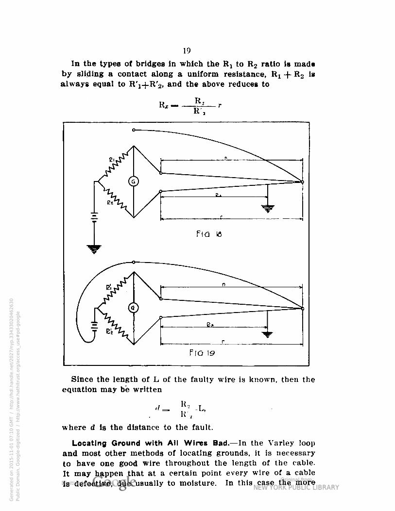
In the types of bridges in which the Rj to R2 ratio is madeby sliding a contact along a uniform resistance, Rx -\
-
R2 isalways equal to R'j-j-R'j, and the above reduces to
Since the length of L of the faulty wire is known, then theequation may be written
R",
where d is the distance to the fault.
Locating Ground with All Wires Bad.— In the Varley loop
and most other methods of locating grounds, it is necessary
to have one good wire throughout the length of the cable.
It may happen that at a certain point every wire of a cable
Is defective, due usually to moisture. In this case the more
Genera
ted o
n 2
01
5-1
1-0
1 0
7:1
0 G
MT /
htt
p:/
/hd
l.hand
le.n
et/
20
27
/nyp.3
34
33
02
04
62
63
0Public
Dom
ain
, G
oog
le-d
igit
ized
/
htt
p:/
/ww
w.h
ath
itru
st.o
rg/a
ccess
_use
#pd-g
oogle
20
common Wheatstone bridge methods cannot be used. If a
megger, galvanometer or voltmeter Is available for determining the insulation resistance to ground of two wires, the
following method may be employed to locate the trouble,
Pig. 15.
R, Rx and R2 are the bridge arms, Gt is the insulation re
sistance to ground of the best wire, G2 is the insulation re
sistance to ground of a bad wire, R0 is the full loop resistance
as estimated from wire tables, and Rx is the resistance of a
single conductor out to the fault. The wires for determining
the insulation resistances G} and G2 should be selected so
that G2 will always be less than Gi-When the two wires are shorted at the far end as showu
and a balance secured on tne bridge, the following equation
is true:
The distance out to the fault can then be computed by-
dividing the resistance Rx by the resistance per foot of the
wire.Locating an Open.— To locate an open circuit in a wire, a
simple capacitance test can be used effectively. The far
terminals of the pair are left open. A buzzer circuit is used
and connected between a known variable resistance arm and
ground, Fig. 17. A telephone receiver is connected across the
total resistance. Calling Cj the capacitance of the good wire
and C2 the capacitance of the faulty wire out to the break,
the resistances R] and R2 are adjusted until the buzz in the
receiver is a minimum. Under this condition the followingratio Is true:
In uniform wires and cables the capacitance is directly pro
portional to the length, so that in the above equation,
where Dt is the length of the good wire and D2 the length of
the bad wire out to the open.
Dx is known, so
R, C2
R2 C*2 D2
Genera
ted o
n 2
01
5-1
1-0
1 0
7:1
0 G
MT /
htt
p:/
/hd
l.hand
le.n
et/
20
27
/nyp.3
34
33
02
04
62
63
0Public
Dom
ain
, G
oog
le-d
igit
ized
/
htt
p:/
/ww
w.h
ath
itru
st.o
rg/a
ccess
_use
#pd-g
oogle
21
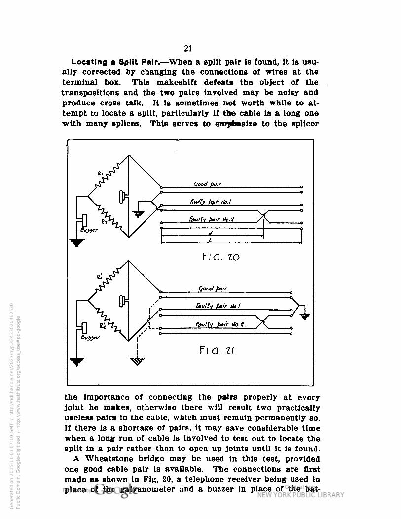
Locating a Split Pair.—When a split pair Is found, It is usually corrected by changing the connections of wires at theterminal box. This makeshift defeats the object of thetranspositions and the two pairs involved may be noisy andproduce cross talk. It is sometimes not worth while to attempt to locate a split, particularly if the cable is a long onewith many splices. This serves to emphasize to the splicer
the importance of connecting the pairs properly at everyjoint he makes, otherwise there will result two practicallyuseless pairs in the cable, which must remain permanently so.
If there is a shortage of pairs, it may save considerable timewhen a long run of cable is involved to test out to locate thesplit in a pair rather than to open up joints until it is found.
A Wheatstone bridge may be used in this test, provided
one good cable pair is available. The connections are firstmade as shown in Fig. 20, a telephone receiver being used inplace of the galvanometer and a buzzer in place of the bat
Genera
ted o
n 2
01
5-1
1-0
1 0
7:1
0 G
MT /
htt
p:/
/hd
l.hand
le.n
et/
20
27
/nyp.3
34
33
02
04
62
63
0Public
Dom
ain
, G
oog
le-d
igit
ized
/
htt
p:/
/ww
w.h
ath
itru
st.o
rg/a
ccess
_use
#pd-g
oogle
tery. The resistance R2 is adjusted until no sound is heard
in the receiver. The ground connections are then changed, as
shown in Fig. 21. These ground connections may be made
either at the far end of the table, as shown by the full lines,
or at the near end of the cable, as shown by the dotted lines.The value of R'2 for a balance Is found as before.
Now, where cl represents the distance to the cross and Lthe length of a pair of wires,
,, _ LR.(»'i—R'i)2KrR 2
— RjR a— R 1R2
(For the purpose of this pamphlet, it is not considered nec
essary to enter into the rather lengthy proof of the above
formula.)Locating a Short.—The location of a short circuit is a sim
ple Wheatstone bridge test, whereby the resistance of the
wire out to the short and return is measured and divided by
two in figuring the equivalent distance.
Precautions in Handling Cable
Circular No. 78, A.E.F., dated July 6, 1918, contains the following instructions relative to handling cable:
Results obtained over the lead cable and Ferrin cable sys
tems in use by the Signal Corps "will depend largely upon the
manner in which the cable is handled prior to installation.For this reason the following instructions will be observed:
"(a) Reels containing cable will be so located in yards or
warehouses as to minimize the possibility of damage
to the cable.
"(b) Reels containing cable will be relagged after a section
of the cable is removed.
"(c) Cable on lagged and unlagged reels will be securely
lashed and fastened to the reel in such a manner as to
prevent movement of the cable on the reel while being
transported.
"(d) All paper cable on reels and sections of reels during
installation will be securely sealed by means of a
floated solder seal.
"(e) Paper insulated cable will not be used as jumper cableby forming it In the shape usually prescribed forswitchboard cable, thereby exposing the paperinsulation."
Genera
ted o
n 2
01
5-1
1-0
1 0
7:1
1 G
MT /
htt
p:/
/hd
l.hand
le.n
et/
20
27
/nyp.3
34
33
02
04
62
63
0Public
Dom
ain
, G
oog
le-d
igit
ized
/
htt
p:/
/ww
w.h
ath
itru
st.o
rg/a
ccess
_use
#pd-g
oogle

Genera
ted o
n 2
01
5-1
1-0
1 0
7:1
1 G
MT /
htt
p:/
/hd
l.hand
le.n
et/
20
27
/nyp.3
34
33
02
04
62
63
0Public
Dom
ain
, G
oog
le-d
igit
ized
/
htt
p:/
/ww
w.h
ath
itru
st.o
rg/a
ccess
_use
#pd-g
oogle