Embed Size (px)
Citation preview
SUBCOURSE EDITIONOD1633 8
BASIC ELECTRONICS
US ARMY ARMAMENT REPAIRTECHNICIAN WARRANT OFFICER
ADVANCED CORRESPONDENCE COURSE
MOS/SKILL LEVEL: 421A
BASIC ELECTRONICS
SUBCOURSE NO. OD1633
US Army CorrespondenceCourse Program
6 Credit Hours
GENERAL
The objective of this subcourse is to introduce the student to theprinciples of basic electronics. In task one of the subcourse text, thestudent will learn the elements of electricity, safety requirements,voltage, current, resistance functions, Ohm's law, and resistor color codes.
In task two, the student will employ the knowledge gained in task one tomeasure and compute voltage. In addition, we will cover the three types ofcircuits that will be encountered in the electronics field and how batteriesare connected to each of these circuits.
Six credit hours are awarded for successful completion of this subcourse.
Lesson 1: BASIC ELECTRONICS
TASK 1: Describe the elements of electricity, safety requirements,voltage, current, resistance functions, Ohm's law, and resistor colorcodes.
TASK 2: Describe series, parallel, and series-parallel circuits,compute and measure voltage, and the current of batteries connected inseries-parallel circuits.
i
BASIC ELECTRONICS - OD1633
TABLE OF CONTENTS
Section Page
TITLE ................................................................. i
TABLE OF CONTENTS ..................................................... ii
Lesson 1: BASIC ELECTRONICS ........................................... 1
Task 1: Describe the elements of electricity, safetyrequirements, voltage, current, resistance functions,Ohm's law, and resistor color codes .............................. 1
Task 2: Describe series, parallel, and series-parallelcircuits, compute and measure voltage, and the current ofbatteries connected in series-parallel circuits .................. 25
Practical Exercise 1 ............................................. 103
Answers to Practical Exercise 1 .................................. 105
REFERENCES ............................................................ 106
ii

BASIC ELECTRONICS - OD1633
THIS PAGE INTENTIONALLY LEFT BLANK
iii
BASIC ELECTRONICS - OD1633
STUDENT NOTES
iv

BASIC ELECTRONICS - OD1633 - LESSON 1/TASK 1
LESSON 1
BASIC ELECTRONICS
TASK 1. Describe the elements of electricity, safety requirements,voltage, current, resistance functions, Ohm's law, and resistorcolor codes.
CONDITIONS
Within a self-study environment and given the subcourse text, withoutassistance.
STANDARDS
Within one hour
REFERENCES
No supplementary references are needed for this task.
1. Introduction
Electricity and electronics are a part of our everyday lives. When we getup in the morning the first thing we do is turn on the light; we have justused electricity. The television that we watch, the stereos and radios thatwe listen to, our heat, our air conditioning, frequently even our cookingall use electricity in one form or another.
Electricity also has many applications from a military standpoint. Thesighting devices for artillery pieces often use electricity to enable thegun crew to aim the weapon at night, or in periods of limited visibility.The fire direction computers are used to semi-accurately aim weapons andweapons systems.
As an Armament Repair Technician you will manage activities and personnelengaged in intermediate direct support/intermediate general support(IDS/TGS) and depot maintenance of field artillery and related fire controldevices. Since many of
1
BASIC ELECTRONICS - OD1633 - LESSON 1/TASK 1
these devices work on electrical principles, you should possess a thoroughknowledge of the principles of electricity and electronics. The purpose ofthis subcourse is to introduce the student to the principles of basicelectronics. This task will discuss what electricity is, the safetyrequirements and first aid for working around electricity, voltage, current,resistance, Ohm's law, and the color codes for resistors.
In the succeeding task, we will cover the different types of circuits, themeans of measuring and computing voltage, and current of batteries,especially those in a series-parallel circuit.
2. Electricity
a. Composition of Matter. Matter is defined as anything that occupiesspace and has weight; that is, the weight and dimensions of all matter canbe measured. Examples of matter include air, water, automobiles, clothing,and even our own bodies. Therefore, we can say that matter may be found inany one of three states: solid, liquid, and gaseous.
All material substances, solids, liquids, and gases, are made up of tinyparticles known as atoms. Atoms combine in small groups of two or more toform molecules. Atoms can be further subdivided into smaller particles,some of which have positive electrical charges and others which havenegative electrical charges. The atoms of different material substances arediscussed in the following paragraphs.
(1) There are over 100 different basic materials in the universe.These basic materials are called elements. Iron is one element, copper,aluminum, oxygen, hydrogen, and mercury are other elements. An element getsits name from the fact that it cannot be broken down easily into simpler (ormore elemental) substances. In other words, these 100 basic elements arethe building materials from which the universe is made. Close study of anyone of these elements reveals that it is made up of those same basicparticles, having a positive or a negative electrical charge.
(2) The basic particles that make up all the elements, and thus theuniverse, are called protons, electrons, and neutrons. A proton is a basic
2
BASIC ELECTRONICS - OD1633 - LESSON 1/TASK 1
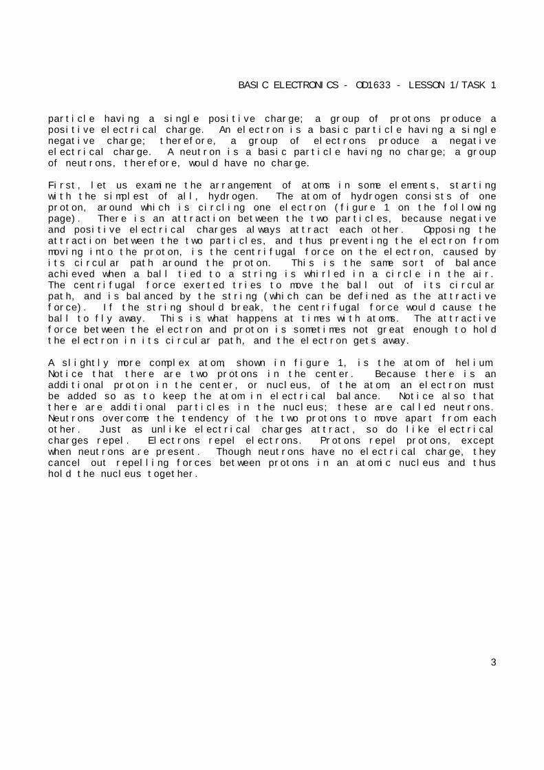
particle having a single positive charge; a group of protons produce apositive electrical charge. An electron is a basic particle having a singlenegative charge; therefore, a group of electrons produce a negativeelectrical charge. A neutron is a basic particle having no charge; a groupof neutrons, therefore, would have no charge.
First, let us examine the arrangement of atoms in some elements, startingwith the simplest of all, hydrogen. The atom of hydrogen consists of oneproton, around which is circling one electron (figure 1 on the followingpage). There is an attraction between the two particles, because negativeand positive electrical charges always attract each other. Opposing theattraction between the two particles, and thus preventing the electron frommoving into the proton, is the centrifugal force on the electron, caused byits circular path around the proton. This is the same sort of balanceachieved when a ball tied to a string is whirled in a circle in the air.The centrifugal force exerted tries to move the ball out of its circularpath, and is balanced by the string (which can be defined as the attractiveforce). If the string should break, the centrifugal force would cause theball to fly away. This is what happens at times with atoms. The attractiveforce between the electron and proton is sometimes not great enough to holdthe electron in its circular path, and the electron gets away.
A slightly more complex atom, shown in figure 1, is the atom of helium.Notice that there are two protons in the center. Because there is anadditional proton in the center, or nucleus, of the atom, an electron mustbe added so as to keep the atom in electrical balance. Notice also thatthere are additional particles in the nucleus; these are called neutrons.Neutrons overcome the tendency of the two protons to move apart from eachother. Just as unlike electrical charges attract, so do like electricalcharges repel. Electrons repel electrons. Protons repel protons, exceptwhen neutrons are present. Though neutrons have no electrical charge, theycancel out repelling forces between protons in an atomic nucleus and thushold the nucleus together.
3

BASIC ELECTRONICS - OD1633 - LESSON 1/TASK 1
FIGURE 1. COMPOSITION OF MATTER.
A still more complex atom, shown in figure 1, is the atom of lithium, alight, soft metal. Note that a third proton has been added to the nucleusand that a third electron is now circling around the nucleus. There arealso two additional neutrons in the nucleus; these are needed to hold thethree protons together.
The atoms of other elements can be analyzed in a similar manner. As theatomic scale increases in complexity, protons and neutrons are added one byone to the nucleus and electrons to the outer circles or shells, as they aretermed by scientists. After lithium comes beryllium with four protons andfive neutrons, boron with five protons and five neutrons, carbon with sixand six, nitrogen with seven and seven, oxygen with eight and eight, and soon. In each of these, there are normally the same number of electronscircling the nucleus as there are protons in the nucleus.
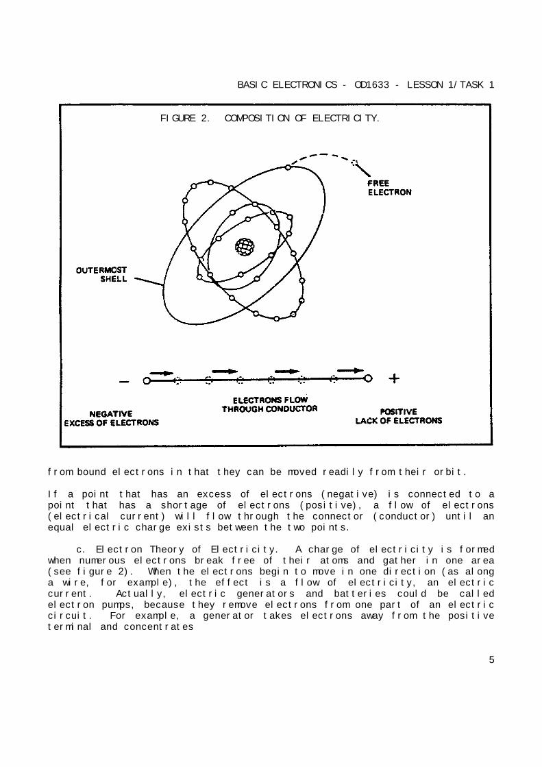
b. Composition of Electricity. When there are more than two electronsin an atom, they will move about the nucleus in different size shells. Theinnermost shells of the atom contain electrons that are not easily freed andare referred to as bound electrons. The outermost shell will contain whatare referred to as free electrons (see figure 2 on the following page).These free electrons differ
4
BASIC ELECTRONICS - OD1633 - LESSON 1/TASK 1
FIGURE 2. COMPOSITION OF ELECTRICITY.
from bound electrons in that they can be moved readily from their orbit.
If a point that has an excess of electrons (negative) is connected to apoint that has a shortage of electrons (positive), a flow of electrons(electrical current) will flow through the connector (conductor) until anequal electric charge exists between the two points.
c. Electron Theory of Electricity. A charge of electricity is formedwhen numerous electrons break free of their atoms and gather in one area(see figure 2). When the electrons begin to move in one direction (as alonga wire, for example), the effect is a flow of electricity, an electriccurrent. Actually, electric generators and batteries could be calledelectron pumps, because they remove electrons from one part of an electriccircuit. For example, a generator takes electrons away from the positiveterminal and concentrates
5
BASIC ELECTRONICS - OD1633 - LESSON 1/TASK 1
them at the negative terminal. Because the electrons repel each other (likeelectrical charges repel), the electrons push out through the circuit andflow to the positive terminal (unlike electrical charges attract). Thus, wecan see that an electric current is, in fact, a flow of electrons fromnegative to positive.
This is the reverse of the original idea of current flow. Before scientistsunderstood what electric current was, they assumed that the current flowedfrom positive to negative. Their studies showed that this was wrong; theylearned that current is the electron movement from negative (concentrationof electrons) to positive (lack of electrons).
d. Conductors and Insulators. Any material that will allow electriccurrent to flow through it is an electrical conductor. Any material thatblocks electric current flow is an electrical insulator. Conductors areused in automotive equipment to carry electric current to the electricalsystem components. Insulators are necessary to keep the electric currentfrom taking a shorter route instead of going to the intended component. Theelectrical properties of a substance depend mainly on the number ofelectrons in the outermost orbits of its atoms which cannot, at any time,contain more than eight electrons.
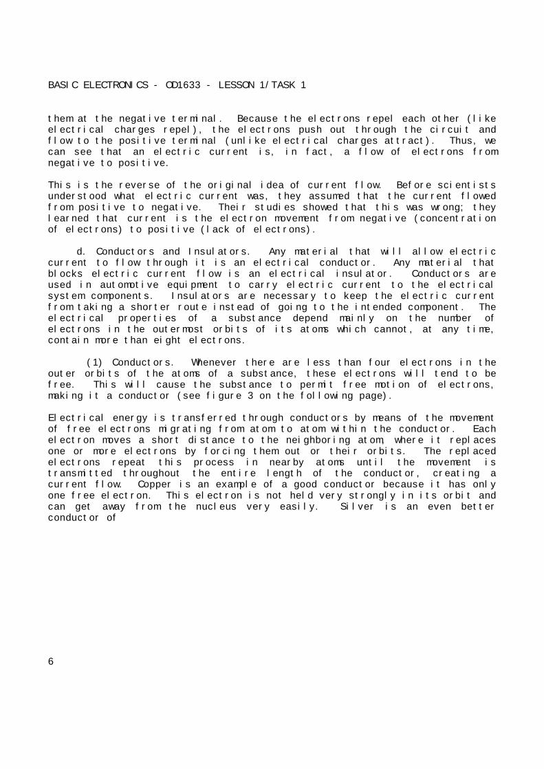
(1) Conductors. Whenever there are less than four electrons in theouter orbits of the atoms of a substance, these electrons will tend to befree. This will cause the substance to permit free motion of electrons,making it a conductor (see figure 3 on the following page).
Electrical energy is transferred through conductors by means of the movementof free electrons migrating from atom to atom within the conductor. Eachelectron moves a short distance to the neighboring atom, where it replacesone or more electrons by forcing them out or their orbits. The replacedelectrons repeat this process in nearby atoms until the movement istransmitted throughout the entire length of the conductor, creating acurrent flow. Copper is an example of a good conductor because it has onlyone free electron. This electron is not held very strongly in its orbit andcan get away from the nucleus very easily. Silver is an even betterconductor of
6
BASIC ELECTRONICS - OD1633 - LESSON 1/TASK 1
FIGURE 3. CONDUCTORS.
electricity but it is too expensive to be used in any great quantity.Because of this, copper is the conductor most widely used in variousmilitary applications.
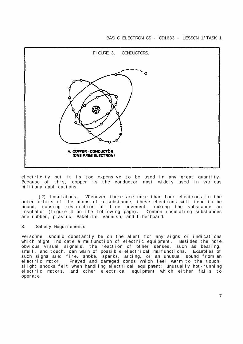
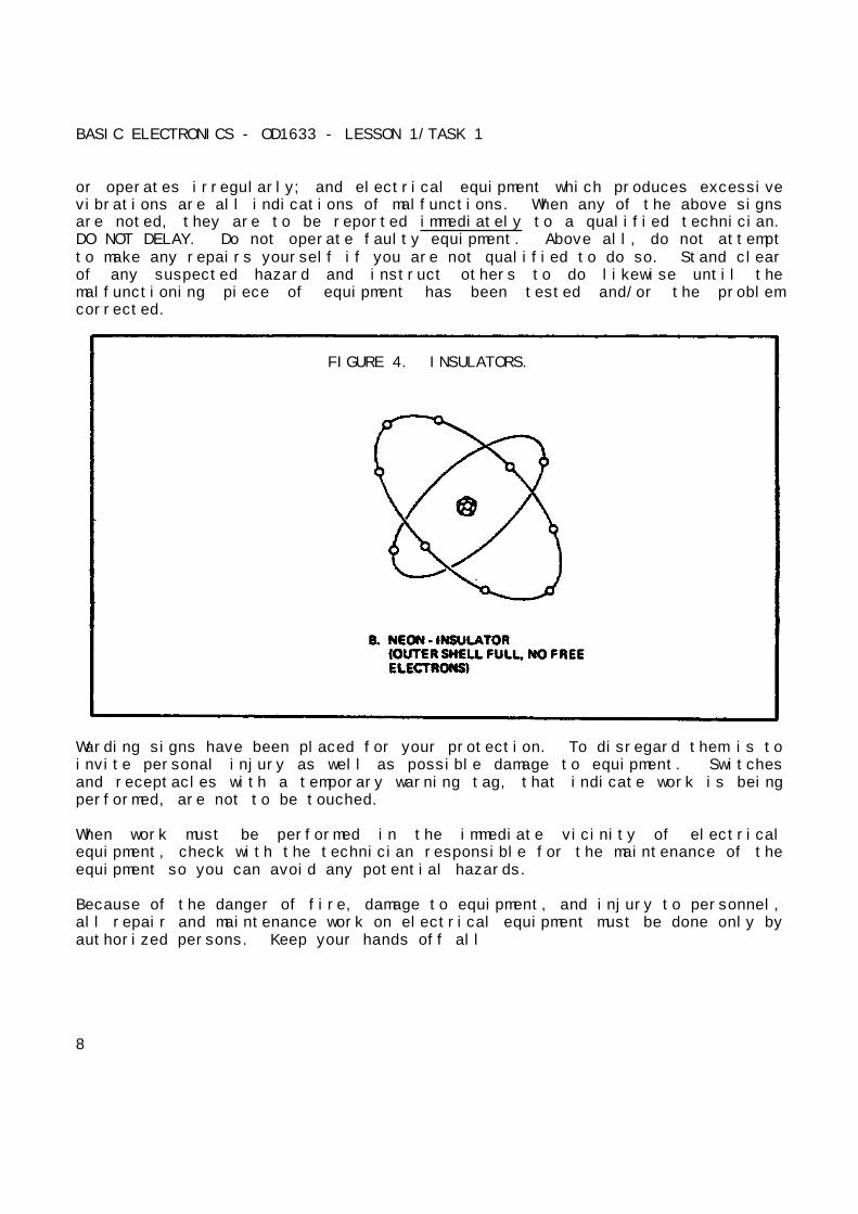
(2) Insulators. Whenever there are more than four electrons in theouter orbits of the atoms of a substance, these electrons will tend to bebound, causing restriction of free movement, making the substance aninsulator (figure 4 on the following page). Common insulating substancesare rubber, plastic, Bakelite, varnish, and fiberboard.
3. Safety Requirements
Personnel should constantly be on the alert for any signs or indicationswhich might indicate a malfunction of electric equipment. Besides the moreobvious visual signals, the reaction of other senses, such as bearing,smell, and touch, can warn of possible electrical malfunctions. Examples ofsuch signs are: fire, smoke, sparks, arcing, or an unusual sound from anelectric motor. Frayed and damaged cords which feel warm to the touch;slight shocks felt when handling electrical equipment; unusually hot-runningelectric motors, and other electrical equipment which either fails tooperate
7
BASIC ELECTRONICS - OD1633 - LESSON 1/TASK 1
or operates irregularly; and electrical equipment which produces excessivevibrations are all indications of malfunctions. When any of the above signsare noted, they are to be reported immediately to a qualified technician.DO NOT DELAY. Do not operate faulty equipment. Above all, do not attemptto make any repairs yourself if you are not qualified to do so. Stand clearof any suspected hazard and instruct others to do likewise until themalfunctioning piece of equipment has been tested and/or the problemcorrected.
FIGURE 4. INSULATORS.
Warding signs have been placed for your protection. To disregard them is toinvite personal injury as well as possible damage to equipment. Switchesand receptacles with a temporary warning tag, that indicate work is beingperformed, are not to be touched.
When work must be performed in the immediate vicinity of electricalequipment, check with the technician responsible for the maintenance of theequipment so you can avoid any potential hazards.
Because of the danger of fire, damage to equipment, and injury to personnel,all repair and maintenance work on electrical equipment must be done only byauthorized persons. Keep your hands off all
8
BASIC ELECTRONICS - OD1633 - LESSON 1/TASK 1
equipment which you have not been specifically authorized to handle.Particularly, stay clear of electrical equipment opened for inspection,testing, and servicing.
Covers for all fuse boxes, junction boxes, switch boxes, and wiringaccessories should be kept closed. Any cover which is not closed, or ismissing, should be reported to the technician responsible for itsmaintenance. Failure to do so may result in injury to personnel and/ordamage to equipment in the event accidental contact is made with exposedlive circuits.
a. Electrical Fires. Carbon dioxide (CO2) is the main firefighting
agent used in electrical fires. However, potassium chloride or purple K(PKP) is also used to fight electrical fires, because it is a noncorrosiveagent. In other words, CO2 will corrode electrical circuits and PKP will
not. Both substances are nonconductive and, therefore, are safe to use interms of electrical safety. If, however, the horn of a CO2 fire
extinguisher is allowed to come in contact with an energized electricalcircuit, an electrical shock may be transmitted to the person handling thefire extinguisher.
The very qualities which cause CO2 and PKP to be valuable extinguishing
agents also makes them dangerous to life. When they replace the oxygen inthe air to the extent that combustion cannot be sustained, breathing alsocannot be sustained. Exposure of a person to high concentrations of CO2 or
PKP will cause suffocation. For this reason, if you must fight anelectrical fire in an enclosed space, wear an oxygen producing respiratorand have assistants standing by to render assistance.
b. First Aid for Electric Shock. A fatal shock can occur from 0.1amperes of current. However, voltages as low as 30 volts have been recordedas causing fatality. It is current which kills, not voltage.
A person who has stopped breathing is not necessarily dead, but is inimmediate danger. Life is dependent upon oxygen, which is breathed into thelungs and then carried by the blood to every body cell. Since body cellscannot store oxygen, and since the blood can hold only a limited amount
9

BASIC ELECTRONICS - OD1633 - LESSON 1/TASK 1
(and that only for a short time), death will surely result from continuedlack of breathing.
However, the heart may continue to beat for some time after breathing hasstopped, and the blood may still be circulated to body cells. Since theblood will, for a short time, contain a small supply of oxygen, the bodycells will not die immediately. For a very few minutes, there is somechance that the person's life may be saved.
The process by which a person who has stopped breathing can be saved iscalled ARTIFICIAL VENTILATION (RESPIRATION). The purpose of artificialrespiration is to force air out of the lungs and into the lungs, in rhythmicalternation, until natural breathing is re-established. Artificialrespiration should be given only when natural breathing has stopped. Itshould NOT be given to any person who is breathing naturally. You shouldnot assume that an individual who is unconscious due to electrical shock hasstopped breathing. To tell if someone suffering from an electrical shock isbreathing, place your bands on the person's sides, at the level of thelowest ribs. If the victim is breathing, you will usually be able to feelthe movement. Remember: DO NOT GIVE ARTIFICIAL RESPIRATION TO A PERSON WHOIS BREATHING NATURALLY. Records show that seven out of ten victims ofelectric shock were revived when artificial respiration was started in lessthan three minutes. After three minutes, the chances of revival decreaserapidly.
Once it has been determined that breathing has stopped, the person nearestthe victim should start the artificial respiration without delay and sendothers for assistance and medical aid. The only logical, permissible delayis that required to free the victim from contact with the electricity in thequickest, safest way. This step, while it must be done quickly, must bedone with great care; otherwise, there may be two victims instead of one.In the case of portable electric tools, lights, appliances, equipment, orportable outlet extensions, this should be done by turning off the powersupply. This can be accomplished in one of two ways; (1) by simply turningoff the switch, (2) by removing the power cord from the receptacle. If theswitch or receptacle cannot be quickly located, the suspected electricaldevice may be pulled free of the victim. Other persons arriving on thescene
10
BASIC ELECTRONICS - OD1633 - LESSON 1/TASK 1
must be clearly warned not to touch the suspected equipment until it hasbeen deenergized. Aid should be enlisted to unplug the device as soon aspossible. The injured person should be pulled free of contact withstationary equipment (such as a bus bar) if the equipment cannot be quicklydeenergized, or if considerations of military operation or unit survivalprevent immediate shutdown of the circuits.
This can be done quickly and safely by carefully applying the followingprocedures:
First, protect yourself with dry insulating material. Then use a dry board,belt, clothing, or other available nonconductive material to free the victimfrom electrical contact. DO NOT TOUCH THE VICTIM UNTIL THE SOURCE OFELECTRICITY HAS BEEN REMOVED.
Once the victim has been removed from the electrical source, it should bedetermined if the person is breathing. If the person is not breathing, amethod of artificial respiration is used. Sometimes victims of electricalshock suffer cardiac arrest (heart stoppage) as well as loss of breathing.Artificial respiration alone is not enough in cases where the heart hasstopped. A technique known as cardio-pulmonary resuscitation (CPR) has beendeveloped to provide aid to a person who has stopped breathing and suffereda cardiac arrest. CPR is relatively easy to learn and is taught in coursesavailable from the American Red Cross and most post installations, as wellas from other civilian and military sources.
4. Voltage, Current, and Resistance
Every electrical circuit includes voltage, current, and resistance. Even asimple circuit consisting of a battery, wires, and a lamp has voltage,current, and resistance. The battery supplies the voltage which forcescurrent through the wires and the lamp. The wires and lamp offer a certainamount of resistance to the current. The way in which current, voltage, andresistance affect each other is expressed in Ohm's law. Ohm's law uses "I"to represent current, "E" to represent voltage, and "R" to representresistance.
In the paragraphs that follow, we will define the voltage, resistance, andcurrent relationship
11
BASIC ELECTRONICS - OD1633 - LESSON 1/TASK 1
stated by Ohm's law, and provide examples of applying Ohm's law to a basicelectrical circuit.
a. Amperage (Current) and Voltage.
(1) Amperes. Current flow, or electron flow, is measured in amperes(I). While it is normally considered that one ampere is a rather smallcurrent of electricity (approximately what a 100-watt light bulb woulddraw), it actually involves a tremendous flow of electrons. More than sixbillion electrons a second are required to make up one ampere.
(2) Voltage. Electrons are caused to flow by a difference inelectron balance in a circuit; that is, when there are more electrons in onepart of a circuit than in another, the electrons will move to where they arelacking. This difference in electron concentration is called potentialdifference or voltage (E). The higher the voltage, the greater the electronimbalance becomes. The greater this electron imbalance, the harder the pushon the electrons (more electrons repelling each other) and the greater thecurrent of electrons in the circuit. When there are many electronsconcentrated at the negative terminal of a generator (with a correspondinglack of electrons at the positive terminal), there is a strong repellingforce on the electrons moving in the wire. This is exactly the same assaying that the higher the voltage, the more electric current will flow in acircuit; all other things, such as resistance, being equal.
b. Resistance. Even though a copper wire will conduct electricity withrelative ease, it still offers resistance to electron flow. This resistance(R) is caused by the energy necessary to break the outer shell of electronsfree, and the collisions between the atoms of the conductor and the freeelectrons. It takes force (or voltage) to overcome the resistanceencountered by the flowing electrons. This resistance is expressed in unitscalled Ohms. The resistance of a conductor varies with its length, cross-sectional area, composition, and temperature.
A long wire offers more resistance than a short wire of the same cross-sectional area. The electrons have farther to travel.
12
BASIC ELECTRONICS - OD1633 - LESSON 1/TASK 1
Some elements can lose electrons more readily than other elements. Copperloses electrons easily, so there are always many free electrons in a copperwire. Other elements, such as iron, do not lose their electrons quite aseasily, so there are fewer free electrons in an iron wire (comparing it to acopper wire of the same size). Thus, with fewer free electrons, fewerelectrons can push through an iron wire; that is, the iron wire has a higherresistance than the copper wire.
A small wire (in thickness or cross-sectional area) offers more resistancethan a large wire. In the small wire, there are fewer free electrons(because fewer atoms), and thus fewer electrons can push through.
Most metals show an increased resistance with an increase in temperature,while most nonmetals show a decrease in resistance with an increase intemperature. For example, glass (a nonmetal) is an excellent insulator atroom temperature but is a very poor insulator when heated to the point ofbecoming red.
In the next paragraphs, voltage, current, and resistance will be applied toOhm's law.
5. Ohm's Law
a. Defining Ohm's Law. The general statements about voltage, current,and resistance can all be related in a statement known as Ohm's law, namedfor the scientist George Simon Ohm, who first stated that relationship.This law says that voltage is equal to amperage times Ohms. Or, it can bestated as the mathematical formula:
E = I x R
where E is voltage in volts, I is current in amperes, and R is resistance inOhms. For the purpose of solving problems, the Ohm's law formula can beexpressed three ways:
o To find voltage: E = I x R
o To find amperage:
13
BASIC ELECTRONICS - OD1633 - LESSON 1/TASK 1
o To find resistance:
This formula is a valuable one to remember because it makes understandablemany of the things that happen in an electrical circuit. For instance, ifthe voltage remains constant, the current flow goes down if the resistancegoes up. An example of this would be a lighting circuit that is going badin a truck. Suppose the wiring circuit between the battery and the lightshas deteriorated, due to connections becoming poor, strands in the wirebreaking, switch contacts becoming dirty, or other similar problems. All ofthese conditions reduce the electron path or, in other words, increasesresistance. And, with this increased resistance, less current will flow.The voltage of the battery stays the same (for example, 12 volts). If theresistance of the circuit when new (including light bulbs) was 6 Ohms, then2 amperes will flow. To satisfy the equation, 12 (volts) must equal amperestimes Ohms resistance (2 x 6). If the resistance goes up to 8 Ohms, only1.5 amperes can flow. The increased resistance cuts down the current flowand, consequently, the amount of light.
b. Applying Ohm's Law. By using Ohm's law, you are able to find theresistance of a circuit, knowing only the voltage and the current in thecircuit.
In any equation, if all the variables (parameters) are known except one,that unknown can be found. For example, using Ohm's law, if current (I) andvoltage (E) are known, resistance (R) (the only parameter not known) can bedetermined as follows:
o Formula:
Referring to figure 5 (on the following page), where E equals 10 volts and Iequals I ampere, solve for R, using the above equation:
o Given: E = 10 volts
I = 1 ampere
14

BASIC ELECTRONICS - OD1633 - LESSON 1/TASK 1
o Solution:
R = 10 Ohms
FIGURE 5. DETERMINING RESISTANCE IN A BASIC CIRCUIT.
Therefore, resistance equals 10 Ohms for the circuit shown in figure 5.
Using the equation below and the circuit shown in figure 6 on the followingpage, we will solve for the unknown E.
o Formula: E = I x R
o Given: I = 0.5 ampere
R = 45 Ohms
o Solution: E = 0.5 ampere x 45 Ohms
E = 22.5 volts
Therefore, voltage equals 22.5 volts for the circuit shown in figure 6.
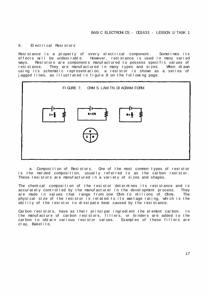
The Ohm's law equation and its various forms may be obtained readily, withthe aid of figure 7 on page
15
BASIC ELECTRONICS - OD1633 - LESSON 1/TASK 1
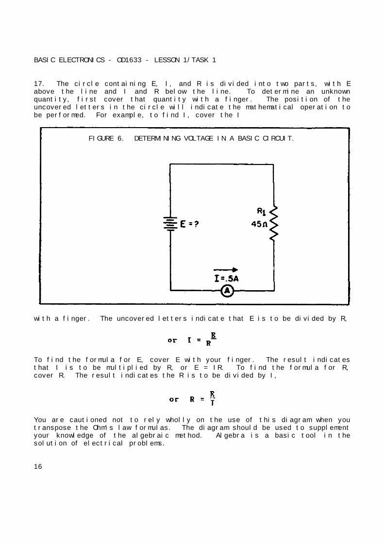
17. The circle containing E, I, and R is divided into two parts, with Eabove the line and I and R below the line. To determine an unknownquantity, first cover that quantity with a finger. The position of theuncovered letters in the circle will indicate the mathematical operation tobe performed. For example, to find I, cover the I
FIGURE 6. DETERMINING VOLTAGE IN A BASIC CIRCUIT.
with a finger. The uncovered letters indicate that E is to be divided by R,
To find the formula for E, cover E with your finger. The result indicatesthat I is to be multiplied by R, or E = IR. To find the formula for R,cover R. The result indicates the R is to be divided by I,
You are cautioned not to rely wholly on the use of this diagram when youtranspose the Ohm's law formulas. The diagram should be used to supplementyour knowledge of the algebraic method. Algebra is a basic tool in thesolution of electrical problems.
16
BASIC ELECTRONICS - OD1633 - LESSON 1/TASK 1
6. Electrical Resistors
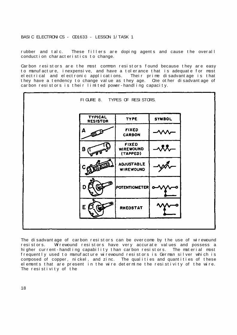
Resistance is a property of every electrical component. Sometimes itseffects will be undesirable. However, resistance is used in many variedways. Resistors are components manufactured to possess specific values ofresistance. They are manufactured in many types and sizes. When drawnusing its schematic representation, a resistor is shown as a series ofjagged lines, as illustrated in figure 8 on the following page.
FIGURE 7. OHM'S LAW TN DIAGRAM FORM.
a. Composition of Resistors. One of the most common types of resistoris the molded composition, usually referred to as the carbon resistor.These resistors are manufactured in a variety of sizes and shapes.
The chemical composition of the resistor determines its resistance and isaccurately controlled by the manufacturer in the development process. Theyare made in values that range from one Ohm to millions of Ohms. Thephysical size of the resistor is related to its wattage rating, which is theability of the resistor to dissipate beat caused by the resistance.
Carbon resistors, have as their principal ingredient the element carbon. Inthe manufacture of carbon resistors, fillers, or binders are added to thecarbon to obtain various resistor values. Examples of these fillers areclay, Bakelite,
17
BASIC ELECTRONICS - OD1633 - LESSON 1/TASK 1
rubber and talc. These fillers are doping agents and cause the overallconduction characteristics to change.
Carbon resistors are the most common resistors found because they are easyto manufacture, inexpensive, and have a tolerance that is adequate for mostelectrical and electronic applications. Their prime disadvantage is thatthey have a tendency to change value as they age. One other disadvantage ofcarbon resistors is their limited power-handling capacity.
FIGURE 8. TYPES OF RESISTORS.
The disadvantage of carbon resistors can be overcome by the use of wirewoundresistors. Wirewound resistors have very accurate values and possess ahigher current-handling capability than carbon resistors. The material mostfrequently used to manufacture wirewound resistors is German silver which iscomposed of copper, nickel, and zinc. The qualities and quantities of theseelements that are present in the wire determine the resistivity of the wire.The resistivity of the
18

BASIC ELECTRONICS - OD1633 - LESSON 1/TASK 1
wire is the measure (or ability) of the wire to resist current. Usually thepercentage of nickel in the wire determines the resistivity. Onedisadvantage of the wirewound resistor is that it takes a large amount ofwire to manufacture a resistor of high ohmic value, thereby increasing thecost. A variation of the wirewound resistor provides an exposed surface tothe resistance wire on one side. An adjustable tap is attached to thisside. Such resistors, sometimes with two or more adjustable taps, are usedas voltage dividers in power supplies and other applications where aspecific voltage is desired to be "tapped" off.
b. Fixed and Variable Resistors. There are two kinds of resistors,fixed and variable. The fixed resistor will have one value and will neverchange (other than through temperature, age, etc.). The resistors (shown inA and B, figure 8 on the previous page) are classed as fixed resistors. Thetapped resistor illustrated in B has several fixed taps and makes more thanone resistance value available. The sliding contact variable resistor shownin C has an adjustable collar that can be moved to tap off any resistancewithin the ohmic value range of the resistor.
There are two types of variable resistors, one called a potentiometer andthe other a rheostat (see views D and E, figure 8). An example of apotentiometer is the volume control on your radio, and an example of therheostat is the dimmer control for the dash lights in an automobile. Thereis a slight difference between them. Rheostats usually have twoconnections, one fixed and the other movable. Any variable resistor canproperly be called a rheostat. The potentiometer always has threeconnections, two fixed and one movable. Generally, the rheostat has alimited range of values and a high current-handling capability. Thepotentiometer has a wide range of values, but it usually has a limitedcurrent-handling capability. Potentiometers are always connected as voltagedividers.
c. Wattage Rating. When a current is passed through a resistor, heatis developed within the resistor. The resistor must be capable ofdissipating this heat into the surrounding air; otherwise, the temperatureof the resistor rises causing a change in resistance, or possibly causingthe resistor to burn out.
19
BASIC ELECTRONICS - OD1633 - LESSON 1/TASK 1
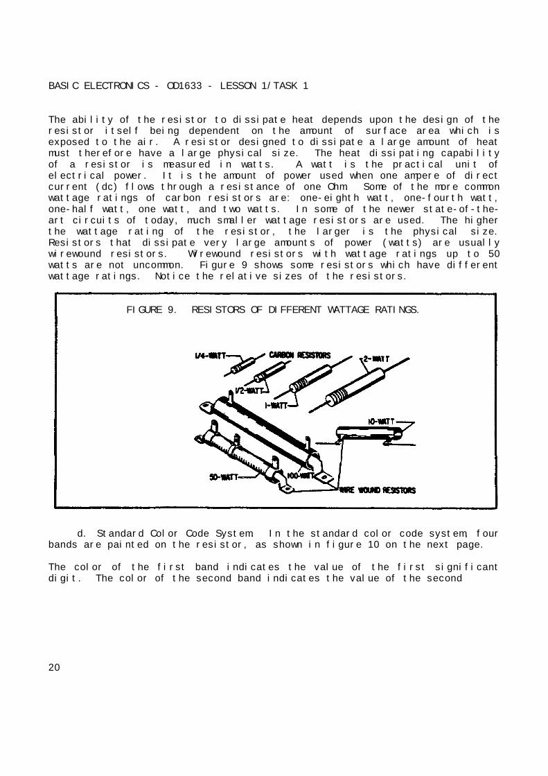
The ability of the resistor to dissipate heat depends upon the design of theresistor itself being dependent on the amount of surface area which isexposed to the air. A resistor designed to dissipate a large amount of heatmust therefore have a large physical size. The heat dissipating capabilityof a resistor is measured in watts. A watt is the practical unit ofelectrical power. It is the amount of power used when one ampere of directcurrent (dc) flows through a resistance of one Ohm. Some of the more commonwattage ratings of carbon resistors are: one-eighth watt, one-fourth watt,one-half watt, one watt, and two watts. In some of the newer state-of-the-art circuits of today, much smaller wattage resistors are used. The higherthe wattage rating of the resistor, the larger is the physical size.Resistors that dissipate very large amounts of power (watts) are usuallywirewound resistors. Wirewound resistors with wattage ratings up to 50watts are not uncommon. Figure 9 shows some resistors which have differentwattage ratings. Notice the relative sizes of the resistors.
FIGURE 9. RESISTORS OF DIFFERENT WATTAGE RATINGS.
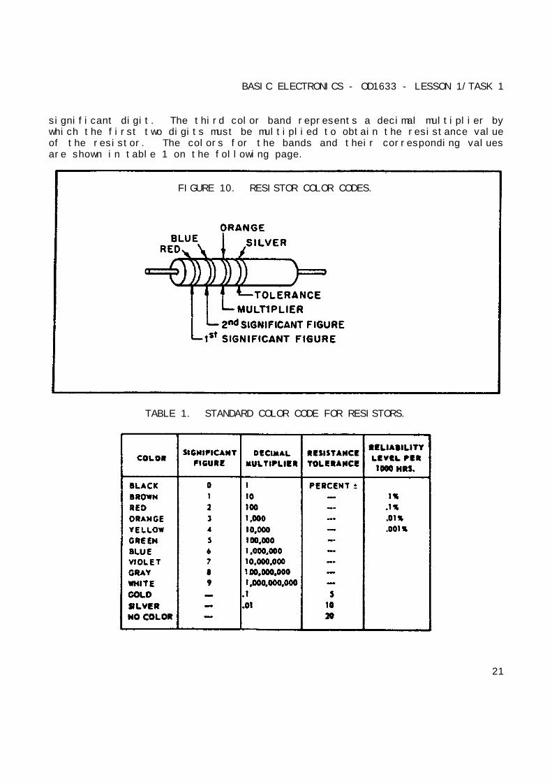
d. Standard Color Code System. In the standard color code system, fourbands are painted on the resistor, as shown in figure 10 on the next page.
The color of the first band indicates the value of the first significantdigit. The color of the second band indicates the value of the second
20
BASIC ELECTRONICS - OD1633 - LESSON 1/TASK 1
significant digit. The third color band represents a decimal multiplier bywhich the first two digits must be multiplied to obtain the resistance valueof the resistor. The colors for the bands and their corresponding valuesare shown in table 1 on the following page.
FIGURE 10. RESISTOR COLOR CODES.
TABLE 1. STANDARD COLOR CODE FOR RESISTORS.
21
BASIC ELECTRONICS - OD1633 - LESSON 1/TASK 1
Use the example colors shown in figure 10. Since red is the color of thefirst band, the first significant digit is 2. The second band is blue;therefore, the second significant digit is 6. The third band is orange,which indicates that the number formed as a result of reading the first twobands is multiplied by 1000. In this case 26 x 1000 = 26,000 Ohms. Thelast band on the resistor indicates the tolerance; that is, themanufacturer's allowable deviation from the numerical value given on theresistor. In this instance its color is silver, and the tolerance is 10percent plus or minus the value of the resistor. The allowed limit ofvariation in ohmic value of this particular resistor is 23,400 to 28,600Ohms.
When measuring resistors you will find situations in which the quantities tobe measured may be extremely large, and the resulting number using the basicunit, the Ohm, may prove too cumbersome. Therefore, a metric system prefixis usually attached to the basic unit of measurement to provide a moremanageable unit. Two of the most commonly used prefixes are kilo and mega.Kilo is the prefix used to represent thousand and is abbreviated k. Mega isthe prefix used to represent million and is abbreviated M.
Simplifying the Color Code. Resistors are the most common components usedin electronics. The technician must identify, select, check, remove, andreplace resistors. Resistors and resistor circuits are usually the easiestbranch of electronics to understand.
The resistor color code sometimes presents problems to a technician. Itreally should not, because once the resistor color code is learned, heshould remember it for the rest of his life.
Black, brown, red, orange, yellow, green, blue, violet, gray, and white isthe order of colors the technician should know automatically. There is amemory aid that will help in remembering the code in its proper order. Eachword starts with the first letter of the colors.
Bad Boys Run Over Yellow Gardenias Behind Victory Garden Walls.
22
BASIC ELECTRONICS - OD1633 - LESSON 1/TASK 1
or
Black BadBrown BoysRed RunOrange OverYellow YellowGreen GardeniasBlue BehindViolet VictoryGray GardenWhite Walls
There are many similar memory aid sentences that are known to experiencedtechnicians. An individual might find one of the other sentences easier toremember.
There is still a good chance that a mistake may be made on a resistor'scolor band. If a mistake is made on the first two significant colors, itusually is not too serious. If a mistake is made on the third band, this ismore serious because the value is going to be at least 10 times too high ortoo low. Some important points to remember about the third band are:
When the third band is...
Black, the resistor must be a value which is less than 100 Ohms.
Red, the resistor must he in hundreds of Ohms.
Orange, the resistor must be in thousands of Ohms.
Yellow, the resistor must be in hundreds of thousands of Ohms.
Green, the resistor must be in megohms.
Blue, the resistor must be in tens of megohms or more.
Red, orange, and yellow are the most common colors for the third band. Ifthis is kept in mind, the selection of resistors from a parts bin will beeasier and a lot of trouble can be avoided.
The fourth band, which is the tolerance band, usually does not present toomuch of a problem. If there is no fourth band, it means that the resistor
23

BASIC ELECTRONICS - OD1633 - LESSON 1/TASK 1
has a 20 percent tolerance, a silver fourth band has a 10 percent tolerance,and a gold fourth band has a 6 percent tolerance. In some cases, the thirdband will be silver or gold. It then becomes a multiplier, and you multiplythe first two bands by 0.01 if it is silver, and 0.1 if it is gold.Resistors that conform to military specifications have an additional fifthband. The fifth band indicates the reliability level per 1000 hours asfollows:
Fifth band color Level
Brown 1.0%Red 0.1%Orange 0.01%Yellow 0.001%
In applying the reliability level table for a resistor color coded brown,the chance of failure will not exceed 1 percent for every 1000 hours ofoperation of that resistor. In a piece of equipment containing 10,000orange fifth band resistors, it means that no more than one resistor willfail during 1000 hours of operation. This is very good reliability.
Both wirewound and composition resistors will not use the resistor colorcode. These resistors will have the ohmic value and tolerance imprinted onthe resistor itself.
7. Conclusion
In this task, we covered the elements of electricity, safety requirements tobe used when working around electricity, voltage, current, resistancefunctions, Ohm's law, and resistor color codes.
In the next task, we will cover series, parallel, and series-parallelcircuits. We will also measure and compute voltage and current of batteriesconnected in series--parallel circuits.
24
BASIC ELECTRONICS - OD1633 - LESSON 1/TASK 2
LESSON 1
BASIC ELECTRONICS
TASK 2. Describe series, parallel, and series-parallel circuits, computeand measure voltage, and the current of batteries connected inseries-parallel circuits.
CONDITIONS
Within a self-study environment and given the subcourse text, withoutassistance.
STANDARDS
Within four hours
REFERENCES
No supplementary references are needed for this task.
1. Introduction
In the introduction to task one, we discussed how electricity andelectronics affect our daily lives. Additionally, we discussed howelectricity and electronics affect us from a military standpoint. As anArmament Repair Technician, you will be involved a great deal withelectricity. Therefore, you should possess a very thorough knowledge ofelectricity and electronics. In task one, the elements of electricity werepresented. Additionally, we covered safety requirements, voltage, current,resistance, Ohm's law and the color code system for resistors.
Task two will put some of this information to use by measuring and computingvoltage. Also, we will cover the different types of circuits and theconnection of batteries in each of these circuits.
25
BASIC ELECTRONICS - OD1633 - LESSON 1/TASK 2
2. Series Circuits and Computing and Measuring Voltage
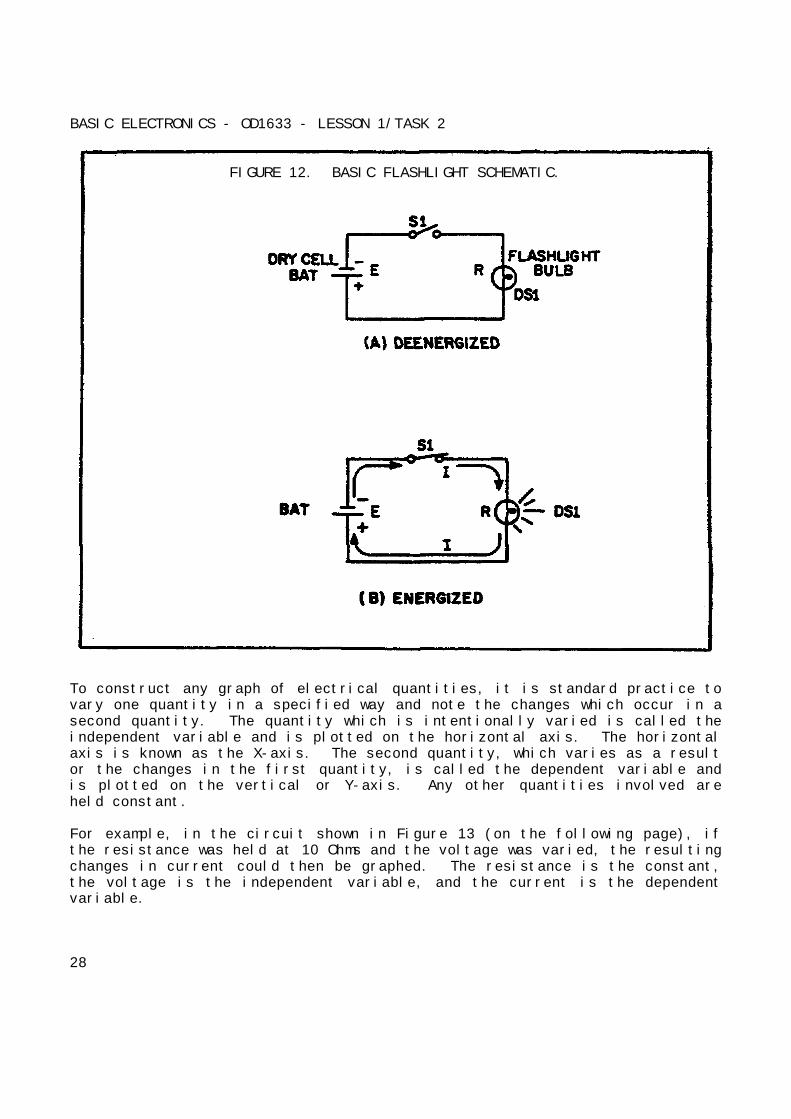
a. The Basic Electric Circuit. The flashlight is an example of a basicelectric circuit. It contains a source of electrical energy (the dry cellsin the flashlight), a load (the bulb) which changes the electrical energyinto a more useful form of energy (light), and a switch to control theenergy delivered to the load.
Before you study a schematic representation of the flashlight, it isnecessary to define certain terms. The load is any device through whichelectrical current flows which changes electrical energy into a more usefulform. Some common examples of loads are a lightbulb, which changeselectrical energy to light energy; an electric motor, which changeselectrical energy into mechanical energy; and the speaker of a radio, whichchanges electrical energy into sound. The source is the device whichfurnishes the electrical energy used by the load. It may consist of asimple dry cell (as in a flashlight), a storage battery (as in anautomobile), or a power supply (such as a battery charger). The switch,which permits control of the electrical device, interrupts the currentdelivered to the load.
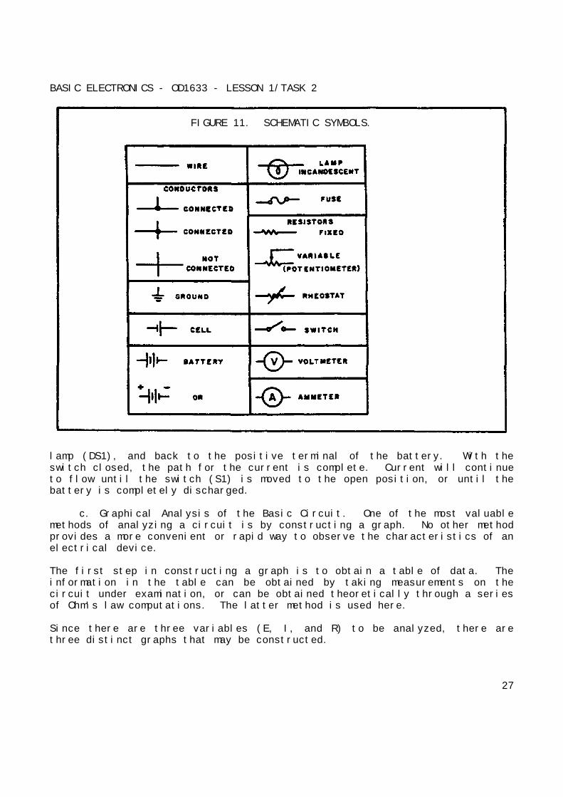
b. Schematic Representation. The technician's main aid introubleshooting a circuit in a piece of equipment is the schematic diagram.The schematic diagram is a "picture" of the circuit that uses symbols torepresent the various circuit components; physically large or complexcircuits can be shown on a relatively small diagram. Before studying thebasic schematic, look at figure 11 on the following page. This figure showsthe symbols that are used in schematic diagrams. These, and others likethem, are referred to and used throughout the study of electricity andelectronics.
The schematic in figure 12 (on page 28) represents a flashlight. Part A ofthe figure shows the flashlight in the off or deenergized state. The switch(S1) is open. There is no complete path for current (I) through thecircuit, and the bulb (DS1) does not light. In figure 12, part B, switch S1is closed. Current flows in the direction of the arrows from the negativeterminal of the battery (BAT), through the switch (SL), through the
26
BASIC ELECTRONICS - OD1633 - LESSON 1/TASK 2
FIGURE 11. SCHEMATIC SYMBOLS.
lamp (DS1), and back to the positive terminal of the battery. With theswitch closed, the path for the current is complete. Current will continueto flow until the switch (S1) is moved to the open position, or until thebattery is completely discharged.
c. Graphical Analysis of the Basic Circuit. One of the most valuablemethods of analyzing a circuit is by constructing a graph. No other methodprovides a more convenient or rapid way to observe the characteristics of anelectrical device.
The first step in constructing a graph is to obtain a table of data. Theinformation in the table can be obtained by taking measurements on thecircuit under examination, or can be obtained theoretically through a seriesof Ohm's law computations. The latter method is used here.
Since there are three variables (E, I, and R) to be analyzed, there arethree distinct graphs that may be constructed.
27
BASIC ELECTRONICS - OD1633 - LESSON 1/TASK 2
FIGURE 12. BASIC FLASHLIGHT SCHEMATIC.
To construct any graph of electrical quantities, it is standard practice tovary one quantity in a specified way and note the changes which occur in asecond quantity. The quantity which is intentionally varied is called theindependent variable and is plotted on the horizontal axis. The horizontalaxis is known as the X-axis. The second quantity, which varies as a resultor the changes in the first quantity, is called the dependent variable andis plotted on the vertical or Y-axis. Any other quantities involved areheld constant.
For example, in the circuit shown in Figure 13 (on the following page), ifthe resistance was held at 10 Ohms and the voltage was varied, the resultingchanges in current could then be graphed. The resistance is the constant,the voltage is the independent variable, and the current is the dependentvariable.
28

BASIC ELECTRONICS - OD1633 - LESSON 1/TASK 2
FIGURE 13. THREE VARIABLES IN A BASIC CIRCUIT.
Figure 14 (on the following page) shows the graph and a table of values.This table shows R held constant at 10 Ohms as E is varied from 0 to 20volts in 5 volt steps. Through the use of Ohm's law, you can calculate thevalue of current for each value of voltage shown in the table. When thetable is complete, the information it contains can be used to construct thegraph shown in figure 14. For example, when the voltage applied to the 10Ohm resistor is 10 volts, the current is 1 ampere. These values of currentand voltage determine a point on the graph. When all five points have beenplotted, a smooth curve is drawn through the points.
Through the use of this curve, the value of current through the resistor canbe quickly determined for any value of voltage between 0 and 20 volts.
Since the curve is a straight line, it shows that equal changes of voltageacross the resistor produce equal changes in current through the resistor.This fact illustrates an important characteristic of the basic law--thecurrent varies directly with the applied voltage when the resistance is heldconstant.
29

BASIC ELECTRONICS - OD1633 - LESSON 1/TASK 2
FIGURE 14. VOLT-AMPERE CHARACTERISTICS.
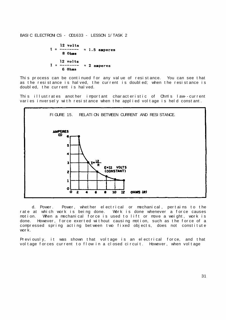
When the voltage across a load is held constant, the current depends solelyupon the resistance of the load. For example, figure 15 (on the followingpage) shows a graph with the voltage held constant at 12 volts. Theindependent variable is the resistance, which is varied from 2 Ohms to 12Ohms. The current is the dependent variable. Values for current can becalculated as:
Given: E = 12 volts
R = 2 Ohms to 12 Ohms
30
BASIC ELECTRONICS - OD1633 - LESSON 1/TASK 2
This process can be continued for any value of resistance. You can see thatas the resistance is halved, the current is doubled; when the resistance isdoubled, the current is halved.
This illustrates another important characteristic of Ohm's law--currentvaries inversely with resistance when the applied voltage is held constant.
FIGURE 15. RELATION BETWEEN CURRENT AND RESISTANCE.
d. Power. Power, whether electrical or mechanical, pertains to therate at which work is being done. Work is done whenever a force causesmotion. When a mechanical force is used to lift or move a weight, work isdone. However, force exerted without causing motion, such as the force of acompressed spring acting between two fixed objects, does not constitutework.
Previously, it was shown that voltage is an electrical force, and thatvoltage forces current to flow in a closed circuit. However, when voltage
31
BASIC ELECTRONICS - OD1633 - LESSON 1/TASK 2
exists but current does not flow because the circuit is open, no work isdone. This is similar to the spring under tension that produced no motion.When voltage causes electrons to move, work is done. The instantaneous rateat which work is done is called the electric power rate, and is measured inwatts.
A total amount of work may be done in different lengths of time. Forexample, a given number of electrons may be moved from one point to anotherin one second or in one hour, depending on the rate at which they are moved.In both cases, the total work done is the same. However, when the work isdone in a short time, the wattage, or instantaneous power rate, is greaterthan when the same amount of work is done over a longer period of time.
As stated, the basic unit of power is the watt. Power, in watts, is equalto the voltage across a circuit multiplied by current through the circuit.This represents the rate at which work is being done at any given instant.The symbol P indicates electrical power. Thus, the basic power formula is P= E x I, where E is volts and I is current in the circuit. The amount ofpower changes when either voltage or current, or both voltage and current,are caused to change.
In practice, the only factors that can be changed are voltage andresistance. In explaining the different forms that formulas may take,current is sometimes presented as a quantity that is changed. Remember, ifcurrent is changed it is because either voltage or resistance has beenchanged.
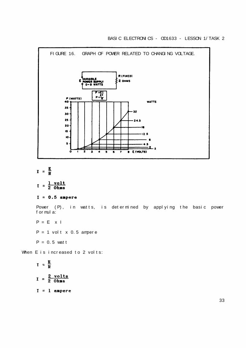
Figure 16 (on the following page) shows a basic circuit using a source ofpower that can be varied from 0 to 8 volts, and a graph that indicates therelationship between voltage and power.
The resistance of this circuit is 2 Ohms; this value does not change.Voltage (E) is increased (by increasing the voltage source), in steps of 1volt, from 0 volts to 8 volts. By applying Ohm's law, the current (I) isdetermined for each step of voltage. For instance, when E is 1 volt, thecurrent is:
32
BASIC ELECTRONICS - OD1633 - LESSON 1/TASK 2
FIGURE 16. GRAPH OF POWER RELATED TO CHANGING VOLTAGE.
Power (P), in watts, is determined by applying the basic powerformula:
P = E x I
P = 1 volt x 0.5 ampere
P = 0.5 watt
When E is increased to 2 volts:
33
BASIC ELECTRONICS - OD1633 - LESSON 1/TASK 2
and
P = E x I
P = 2 volts x 1 ampere
P = 2 watts
When E is increased to 3 volts:
and
P = E x I
P = 3 volts x 1.5 amperes
P = 4.5 watts
You should notice that when the voltage was increased to 2 volts, the powerincreased from .5 watts to 2 watts or 4 times. When the voltage increasedto 3 volts, the power increased to 4.5 watts or 9 times. This shows that ifthe resistance in a circuit is held constant, the power varies directly withthe square of the voltage.
Another way of proving that power varies as the square of the voltage whenresistance is held constant is:
34
BASIC ELECTRONICS - OD1633 - LESSON 1/TASK 2
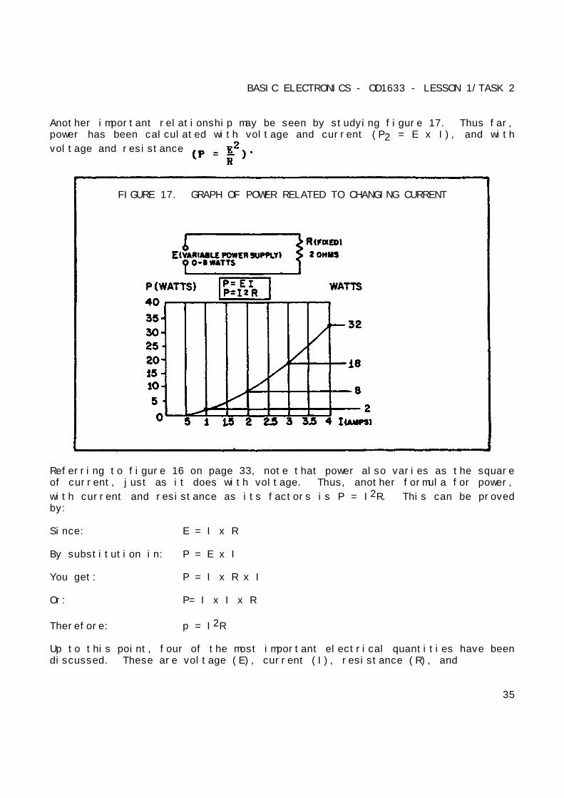
Another important relationship may be seen by studying figure 17. Thus far,power has been calculated with voltage and current (P2 = E x I), and with
voltage and resistance
FIGURE 17. GRAPH OF POWER RELATED TO CHANGING CURRENT
Referring to figure 16 on page 33, note that power also varies as the squareof current, just as it does with voltage. Thus, another formula for power,
with current and resistance as its factors is P = I2R. This can be provedby:
Since: E = I x R
By substitution in: P = E x I
You get: P = I x R x I
Or: P= I x I x R
Therefore: p = I2R
Up to this point, four of the most important electrical quantities have beendiscussed. These are voltage (E), current (I), resistance (R), and
35
BASIC ELECTRONICS - OD1633 - LESSON 1/TASK 2
power (P). You must understand the relationships which exist betweenquantities because they are used throughout your study of electricity. Inthe preceding paragraphs, P was expressed in terms of alternate pairs of theother three basic quantities E, I, and R. In practice, you should be ableto express any one of these quantities in terms of any two of the others.
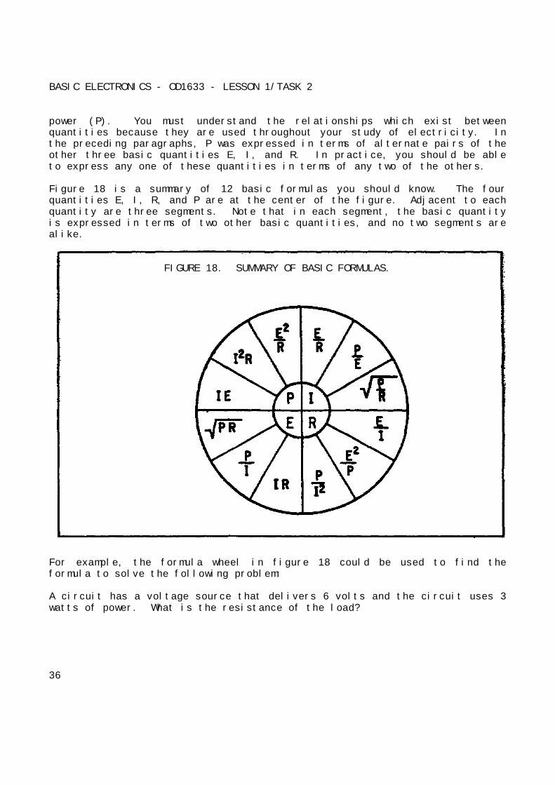
Figure 18 is a summary of 12 basic formulas you should know. The fourquantities E, I, R, and P are at the center of the figure. Adjacent to eachquantity are three segments. Note that in each segment, the basic quantityis expressed in terms of two other basic quantities, and no two segments arealike.
FIGURE 18. SUMMARY OF BASIC FORMULAS.
For example, the formula wheel in figure 18 could be used to find theformula to solve the following problem:
A circuit has a voltage source that delivers 6 volts and the circuit uses 3watts of power. What is the resistance of the load?
36
BASIC ELECTRONICS - OD1633 - LESSON 1/TASK 2
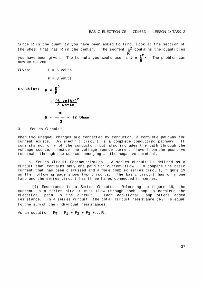
Since R is the quantity you have been asked to find, look at the section of
the wheel that has R in the center. The segment E2 contains the quantitiesR
you have been given. The formula you would use is The problem cannow be solved.
Given: E = 6 volts
P = 3 watts
3. Series Circuits
When two unequal charges are connected by conductor, a complete pathway forcurrent exists. An electric circuit is a complete conducting pathway. Itconsists not only of the conductor, but also includes the path through thevoltage source. Inside the voltage source current flows from the positiveterminal, through the source, emerging at the negative terminal.
a. Series Circuit Characteristics. A series circuit is defined as acircuit that contains only one path for current flow. To compare the basiccurrent that has been discussed and a more complex series circuit, figure 19on the following page shows two circuits. The basic circuit has only onelamp and the series circuit has three lamps connected in series.
(1) Resistance in a Series Circuit. Referring to figure 19, thecurrent in a series circuit must flow through each lamp to complete theelectrical path in the circuit. Each additional lamp offers addedresistance. In a series circuit, the total circuit resistance (RT) is equal
to the sum of the individual resistances.
As an equation: RT = R1 + R2 + R3 +...Rn
37

BASIC ELECTRONICS - OD1633 - LESSON 1/TASK 2
FIGURE 19. COMPARISON OF BASIC AND SERIES CIRCUITS.
FIGURE 20. SOLVING FOR TOTAL RESISTANCE IN A SERIES CIRCUIT.
38
BASIC ELECTRONICS - OD1633 - LESSON 1/TASK 2
NOTEThe subscript n denotes any number of additionalresistance that might be in the equation.
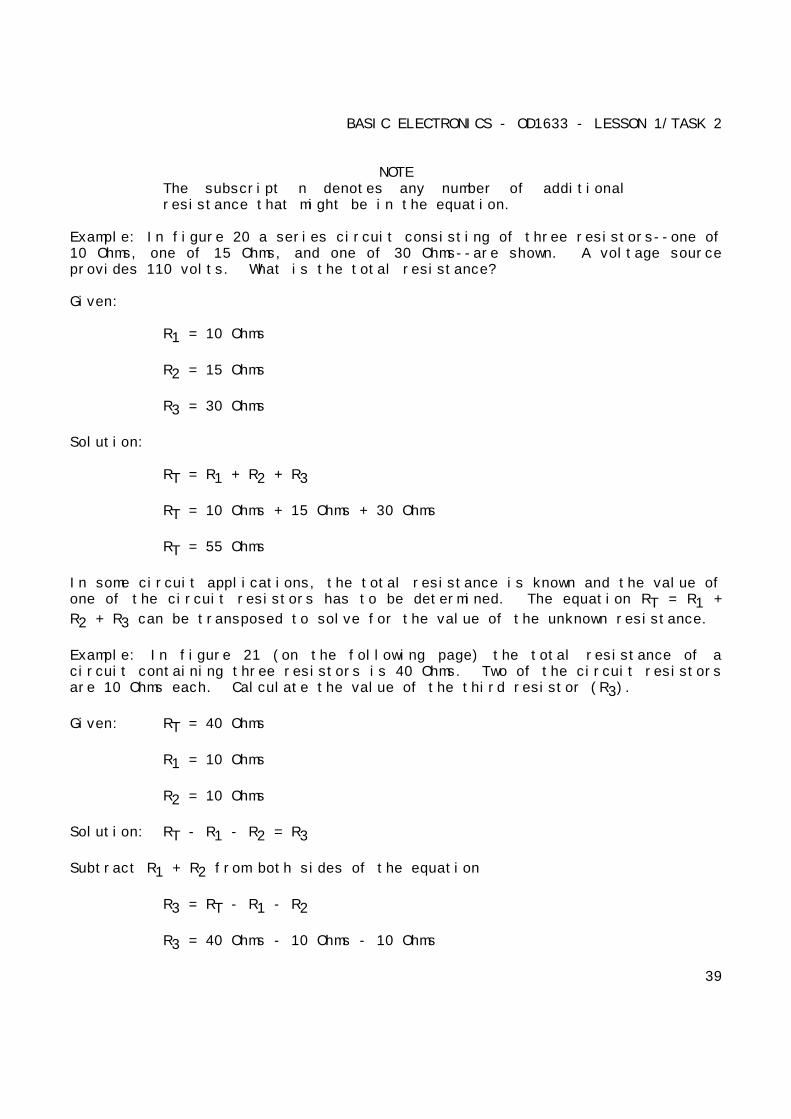
Example: In figure 20 a series circuit consisting of three resistors--one of10 Ohms, one of 15 Ohms, and one of 30 Ohms--are shown. A voltage sourceprovides 110 volts. What is the total resistance?
Given:
R1 = 10 Ohms
R2 = 15 Ohms
R3 = 30 Ohms
Solution:
RT = R1 + R2 + R3
RT = 10 Ohms + 15 Ohms + 30 Ohms
RT = 55 Ohms
In some circuit applications, the total resistance is known and the value ofone of the circuit resistors has to be determined. The equation RT = R1 +
R2 + R3 can be transposed to solve for the value of the unknown resistance.
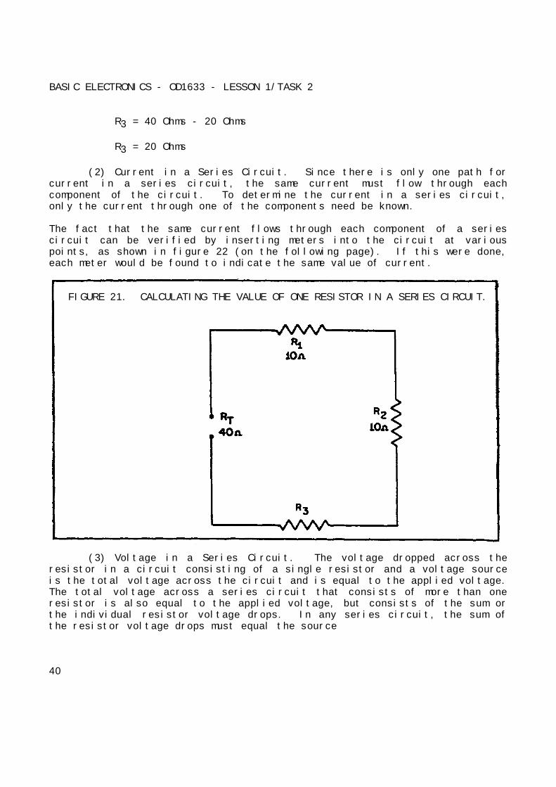
Example: In figure 21 (on the following page) the total resistance of acircuit containing three resistors is 40 Ohms. Two of the circuit resistorsare 10 Ohms each. Calculate the value of the third resistor (R3).
Given: RT = 40 Ohms
R1 = 10 Ohms
R2 = 10 Ohms
Solution: RT - R1 - R2 = R3
Subtract R1 + R2 from both sides of the equation
R3 = RT - R1 - R2
R3 = 40 Ohms - 10 Ohms - 10 Ohms
39
BASIC ELECTRONICS - OD1633 - LESSON 1/TASK 2
R3 = 40 Ohms - 20 Ohms
R3 = 20 Ohms
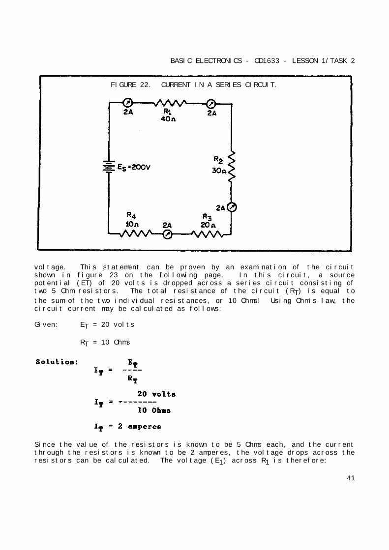
(2) Current in a Series Circuit. Since there is only one path forcurrent in a series circuit, the same current must flow through eachcomponent of the circuit. To determine the current in a series circuit,only the current through one of the components need be known.
The fact that the same current flows through each component of a seriescircuit can be verified by inserting meters into the circuit at variouspoints, as shown in figure 22 (on the following page). If this were done,each meter would be found to indicate the same value of current.
FIGURE 21. CALCULATING THE VALUE OF ONE RESISTOR IN A SERIES CIRCUIT.
(3) Voltage in a Series Circuit. The voltage dropped across theresistor in a circuit consisting of a single resistor and a voltage sourceis the total voltage across the circuit and is equal to the applied voltage.The total voltage across a series circuit that consists of more than oneresistor is also equal to the applied voltage, but consists of the sum orthe individual resistor voltage drops. In any series circuit, the sum ofthe resistor voltage drops must equal the source
40
BASIC ELECTRONICS - OD1633 - LESSON 1/TASK 2
FIGURE 22. CURRENT IN A SERIES CIRCUIT.
voltage. This statement can be proven by an examination of the circuitshown in figure 23 on the following page. In this circuit, a sourcepotential (ET) of 20 volts is dropped across a series circuit consisting oftwo 5 Ohm resistors. The total resistance of the circuit (RT) is equal to
the sum of the two individual resistances, or 10 Ohms! Using Ohm's law, thecircuit current may be calculated as follows:
Given: ET = 20 volts
RT = 10 Ohms
Since the value of the resistors is known to be 5 Ohms each, and the currentthrough the resistors is known to be 2 amperes, the voltage drops across theresistors can be calculated. The voltage (E1) across R1 is therefore:
41
BASIC ELECTRONICS - OD1633 - LESSON 1/TASK 2
Given: I1 = 2 amperes
R1 = 5 Ohms
Solution: E1 = I1 x R1
E1 = 2 amperes x 5 Ohms
E1 = 10 volts
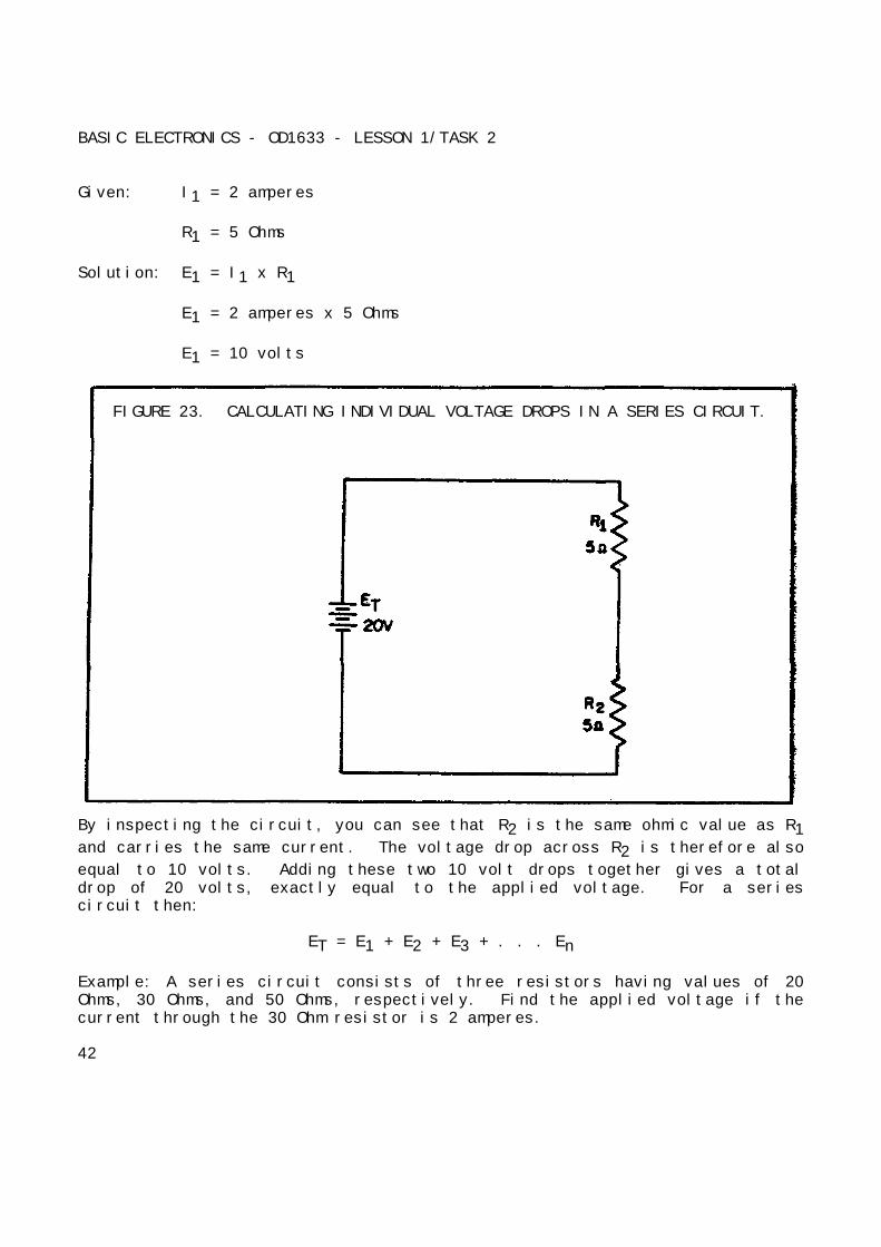
FIGURE 23. CALCULATING INDIVIDUAL VOLTAGE DROPS IN A SERIES CIRCUIT.
By inspecting the circuit, you can see that R2 is the same ohmic value as R1and carries the same current. The voltage drop across R2 is therefore also
equal to 10 volts. Adding these two 10 volt drops together gives a totaldrop of 20 volts, exactly equal to the applied voltage. For a seriescircuit then:
ET = E1 + E2 + E3 + . . . En
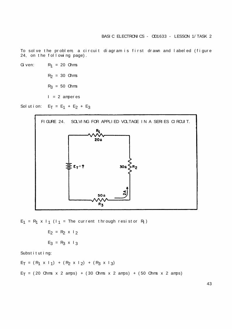
Example: A series circuit consists of three resistors having values of 20Ohms, 30 Ohms, and 50 Ohms, respectively. Find the applied voltage if thecurrent through the 30 Ohm resistor is 2 amperes.
42
BASIC ELECTRONICS - OD1633 - LESSON 1/TASK 2
To solve the problem, a circuit diagram is first drawn and labeled (figure24, on the following page).
Given: R1 = 20 Ohms
R2 = 30 Ohms
R3 = 50 Ohms
I = 2 amperes
Solution: ET = E1 + E2 + E3
FIGURE 24. SOLVING FOR APPLIED VOLTAGE IN A SERIES CIRCUIT.
E1 = R1 x I1 (I1 = The current through resistor Rl)
E2 = R2 x I2
E3 = R3 x I3
Substituting:
ET = (R1 x I1) + (R2 x I2) + (R3 x I3)
ET = (20 Ohms x 2 amps) + (30 Ohms x 2 amps) + (50 Ohms x 2 amps)
43

BASIC ELECTRONICS - OD1633 - LESSON 1/TASK 2
ET = 40 volts + 60 volts + 100 volts
ET = 200 volts
NOTE
When you use Ohm's law, the quantities for theequation must be taken from the same part of thecircuit. In the above example, the voltage across R2was computed using the current through R2 and the
resistance of R2.
The value of the voltage dropped by a resistor is determined by the appliedvoltage and is in proportion to the circuit resistances. The voltage dropsthat occur in a series circuit are in direct proportion to the resistances.This is the result of having the same current flow through each resistor.The larger the ohmic value of the resistor, the larger the voltage dropacross it.
(4) Power in a Series Circuit. Each of the resistors in a seriescircuit consumes power which is dissipated in the form of heat. Since thispower must come from the source, the total power must be equal to the powerconsumed by the circuit resistances. In a series circuit, the total poweris equal to the sum of the power dissipated by the individual resistors.Total power (PT) is equal to:
PT = P1 + P2 + P3 + . . . Pn
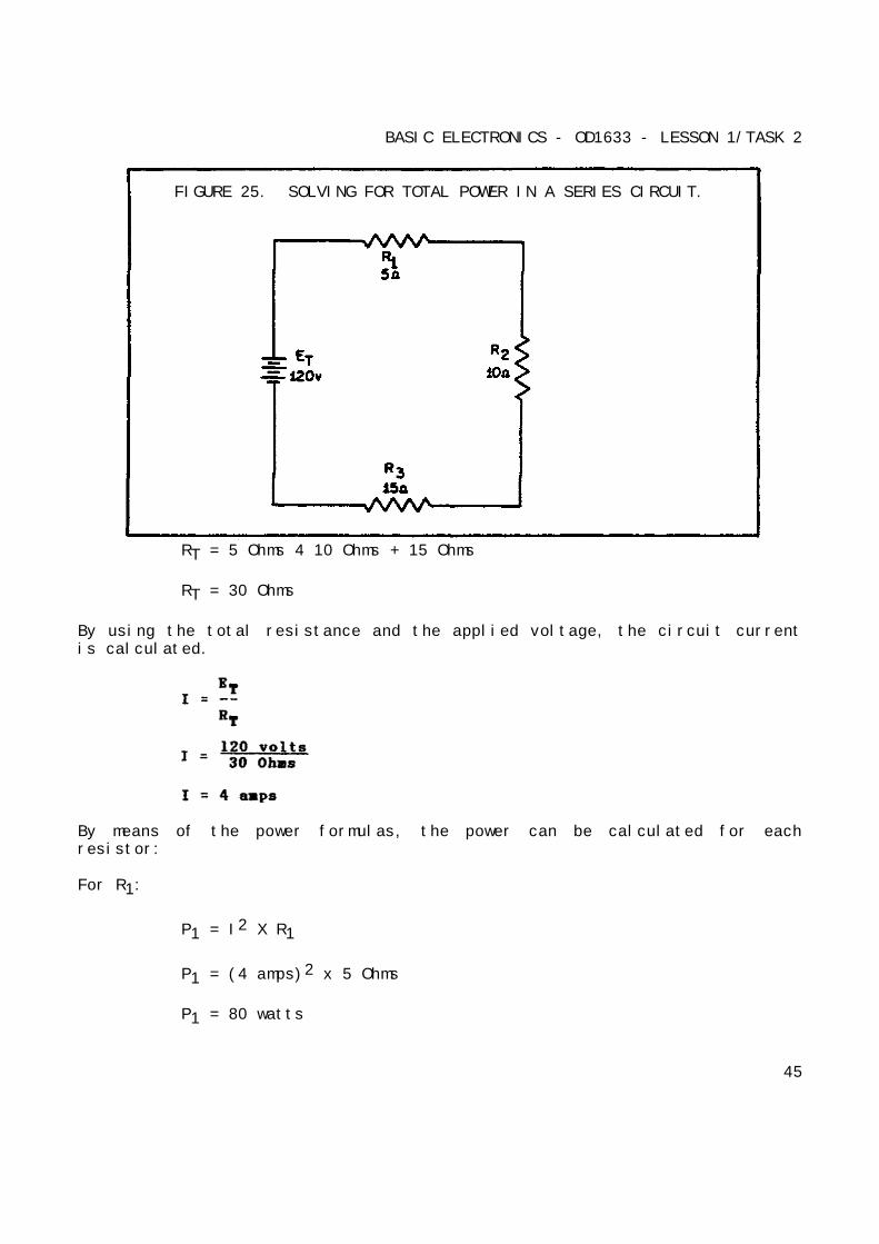
Example: A series circuit consists of three resistors having values of 5Ohms, 10 Ohms, 15 Ohms. Find the total power when 120 volts is applied tothe circuit (figure 25).
Given: R1 = 5 Ohms
R2 = 10 Ohms
R3 = 15 Ohms
E = 120 volts
Solution: RT = R1 + R2 + R3
44
BASIC ELECTRONICS - OD1633 - LESSON 1/TASK 2
FIGURE 25. SOLVING FOR TOTAL POWER IN A SERIES CIRCUIT.
RT = 5 Ohms 4 10 Ohms + 15 Ohms
RT = 30 Ohms
By using the total resistance and the applied voltage, the circuit currentis calculated.
By means of the power formulas, the power can be calculated for eachresistor:
For R1:
P1 = I2 X R1
P1 = (4 amps)2 x 5 Ohms
P1 = 80 watts
45
BASIC ELECTRONICS - OD1633 - LESSON 1/TASK 2
For R2:
P2 = I2 x R1
P = (4 amps)2 x 10 Ohms
P2 = 160 watts
For R3:
P3 = I2 x R3
P = (4 amps)2 x 15 Ohms
P3 = 240 watts
To obtain total power:
PT = P1 + P2 + P3
PT = 80 watts + 160 watts + 240 watts
PT = 480 watts
To check the answer, the total power delivered by the source can becalculated:
Psource = Tsource x Esource
Psource = 4 amps x 120 volts
Psource = 480 watts
The total power is equal to the sum of the power used by the individualresistors.
b. Summary of Characteristics. The important factors governing theoperation of a series circuit are as listed below. These factors have beenset up as a group of rules so that they may be easily studied. These rulesmust be completely understood before the study of more advanced circuittheory is undertaken.
(1) Rules for Series DC Circuits.
(a) The same current flows through each part of a series circuit.
(b) The total resistance of a series circuit is equal to the sumof the individual resistances.
46
BASIC ELECTRONICS - OD1633 - LESSON 1/TASK 2
(c) The total voltage across a series circuit is equal to the sumof the individual voltage drops.
(d) The voltage drop across a resistor in a series circuit isproportional to the ohmic value of the resistor.
(e) The total power in a series circuit is equal to the sum of theindividual powers used by each circuit component.
c. Series Circuit Analysis. To establish a procedure for solvingseries circuits, the following sample problems will be solved.
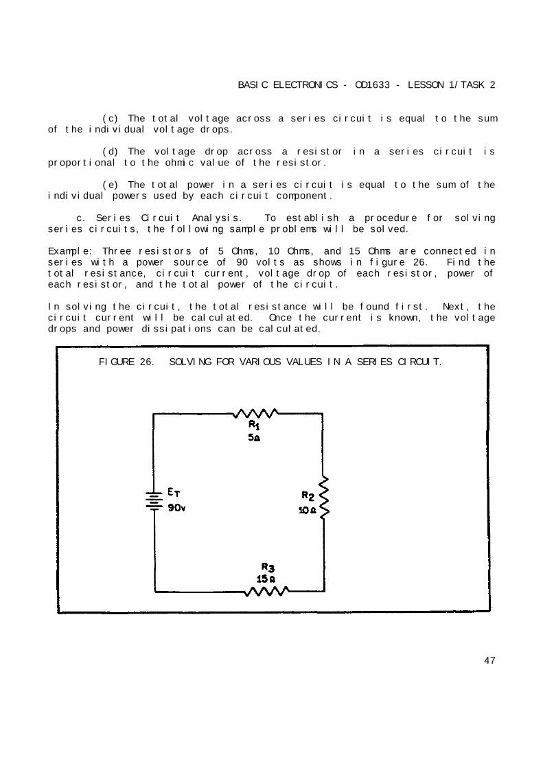
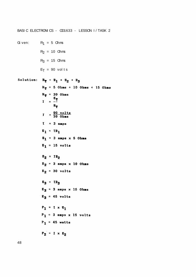
Example: Three resistors of 5 Ohms, 10 Ohms, and 15 Ohms are connected inseries with a power source of 90 volts as shows in figure 26. Find thetotal resistance, circuit current, voltage drop of each resistor, power ofeach resistor, and the total power of the circuit.
In solving the circuit, the total resistance will be found first. Next, thecircuit current will be calculated. Once the current is known, the voltagedrops and power dissipations can be calculated.
FIGURE 26. SOLVING FOR VARIOUS VALUES IN A SERIES CIRCUIT.
47
BASIC ELECTRONICS - OD1633 - LESSON I/TASK 2
Given: R1 = 5 Ohms
R2 = 10 Ohms
R3 = 15 Ohms
ET = 90 volts
48
BASIC ELECTRONICS - OD1633 - LESSON 1/TASK 2
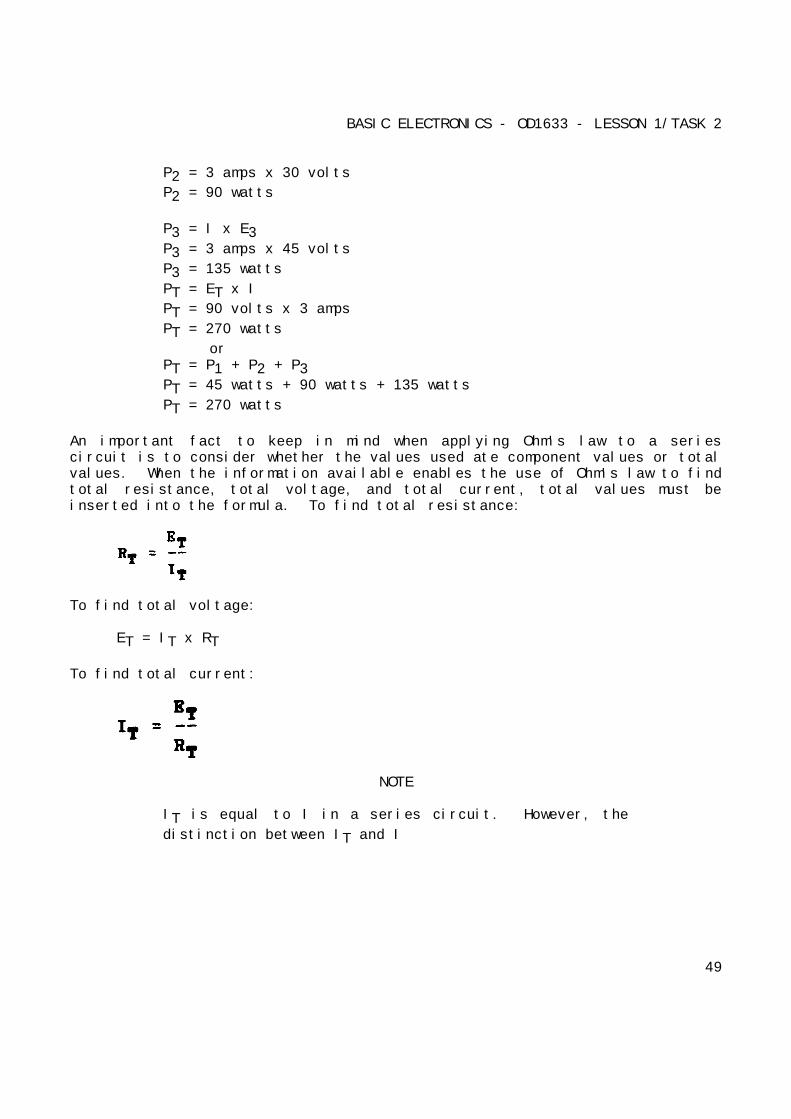
P2 = 3 amps x 30 volts
P2 = 90 watts
P3 = I x E3P3 = 3 amps x 45 volts
P3 = 135 watts
PT = ET x I
PT = 90 volts x 3 amps
PT = 270 watts
orPT = P1 + P2 + P3PT = 45 watts + 90 watts + 135 watts
PT = 270 watts
An important fact to keep in mind when applying Ohm's law to a seriescircuit is to consider whether the values used ate component values or totalvalues. When the information available enables the use of Ohm's law to findtotal resistance, total voltage, and total current, total values must beinserted into the formula. To find total resistance:
To find total voltage:
ET = IT x RT
To find total current:
NOTE
IT is equal to I in a series circuit. However, the
distinction between IT and I
49
BASIC ELECTRONICS - OD1633 - LESSON 1/TASK 2
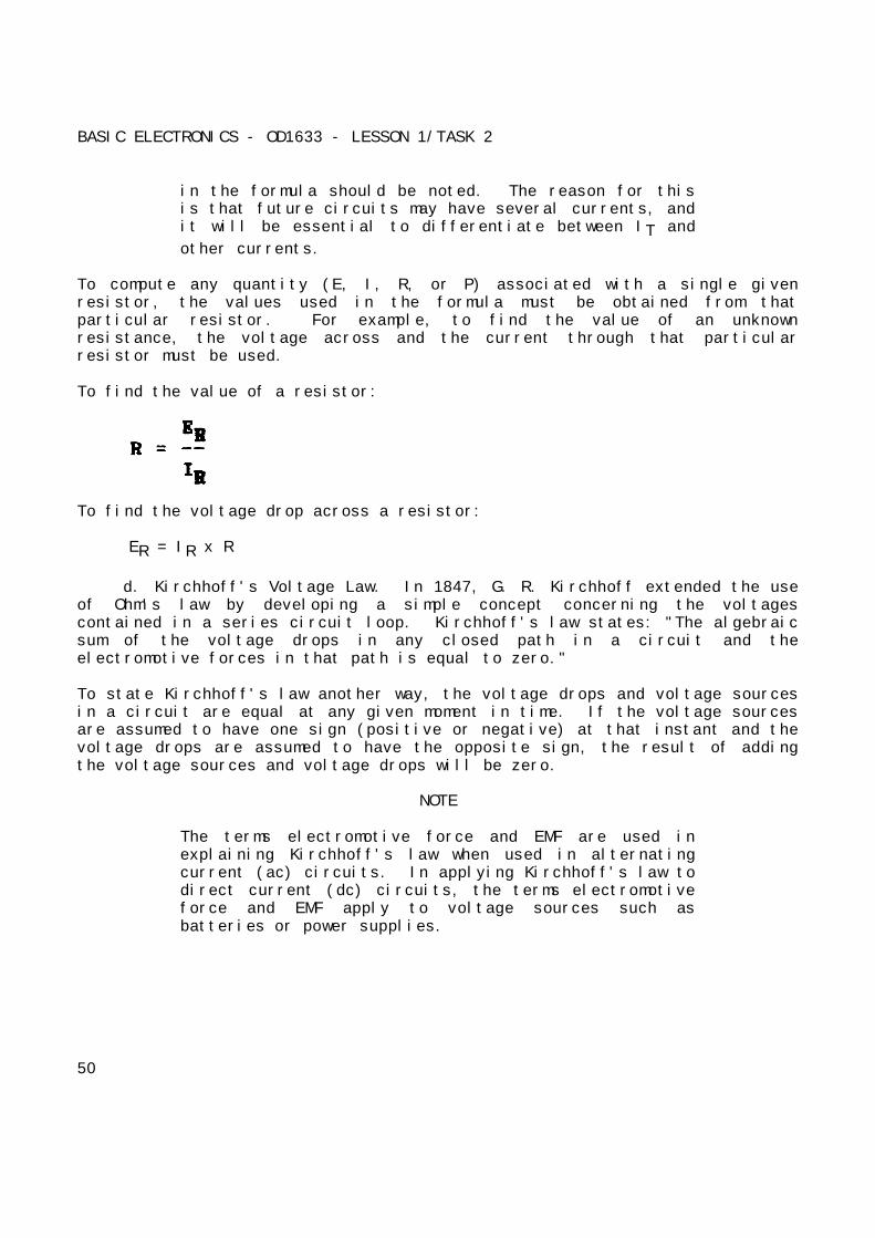
in the formula should be noted. The reason for thisis that future circuits may have several currents, andit will be essential to differentiate between IT and
other currents.
To compute any quantity (E, I, R, or P) associated with a single givenresistor, the values used in the formula must be obtained from thatparticular resistor. For example, to find the value of an unknownresistance, the voltage across and the current through that particularresistor must be used.
To find the value of a resistor:
To find the voltage drop across a resistor:
ER = IR x R
d. Kirchhoff's Voltage Law. In 1847, G. R. Kirchhoff extended the useof Ohm's law by developing a simple concept concerning the voltagescontained in a series circuit loop. Kirchhoff's law states: "The algebraicsum of the voltage drops in any closed path in a circuit and theelectromotive forces in that path is equal to zero."
To state Kirchhoff's law another way, the voltage drops and voltage sourcesin a circuit are equal at any given moment in time. If the voltage sourcesare assumed to have one sign (positive or negative) at that instant and thevoltage drops are assumed to have the opposite sign, the result of addingthe voltage sources and voltage drops will be zero.
NOTE
The terms electromotive force and EMF are used inexplaining Kirchhoff's law when used in alternatingcurrent (ac) circuits. In applying Kirchhoff's law todirect current (dc) circuits, the terms electromotiveforce and EMF apply to voltage sources such asbatteries or power supplies.
50

BASIC ELECTRONICS - OD1633 - LESSON 1/TASK 2
Through the use of Kirchhoff's law, circuit problems can be solved whichwould be difficult, and often impossible, with knowledge of Ohm's law alone.When Kirchhoff's law is properly applied, an equation can be set up for aclosed loop and the unknown circuit values can be calculated.
e. Polarity of Voltage. To apply Kirchhoff's voltage law, the meaningof voltage polarity must be understood. In the circuit shown in figure 27,the current is shown flowing in a counterclockwise direction. Notice thatthe end of resistor R1, into which the current flows, is marked negative
(-). The end of R1, at which the current leaves, is marked positive (+).
These polarity markings are used to show, that the end of R1, into which the
current flows is at a higher negative potential than the end of the resistorat which the current leaves. Point A is more negative than point B.
Point C, which is at the same potential as point B, is labeled negative.This is to indicate that point C is more negative than point D. To say apoint is positive (or negative) without stating what the polarity is basedupon has no meaning. In working with Kirchhoff's law, positive and negativepolarities are assigned in the direction of current flow.
FIGURE 29. VOLTAGE POLARITIES.
51
BASIC ELECTRONICS - OD1633 - LESSON 1/TASK 2
(1) Applications of Kirchhoff's Voltage Law. Kirchhoff's voltage lawcan be written as an equation, as shown below:
Ea + Eb + Ec + ... En = 0
where Ea, Eb, etc., are the voltage drops around any closed circuit loop.
To set up the equation for an actual circuit, the following procedures areused.
(a) Assume a direction of current through the circuit. (Thecorrect direction is desirable but not necessary.)
(b) Using the assumed direction of current, assign polarities toall resistors through which the current flows.
(c) Place the correct polarities on any sources included in thecircuit.
(d) Starting at any point in the circuit, trace around thecircuit, writing down the amount and polarity of the voltage across eachcomponent in succession. The polarity used is the sign after the assumedcurrent has passed through the component. Stop when the point at which thetrace was started is reached.
(e) Place these voltages, with their polarities, into the equationand solve for the desired quantity.
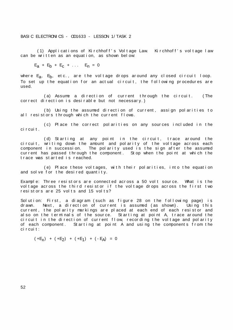
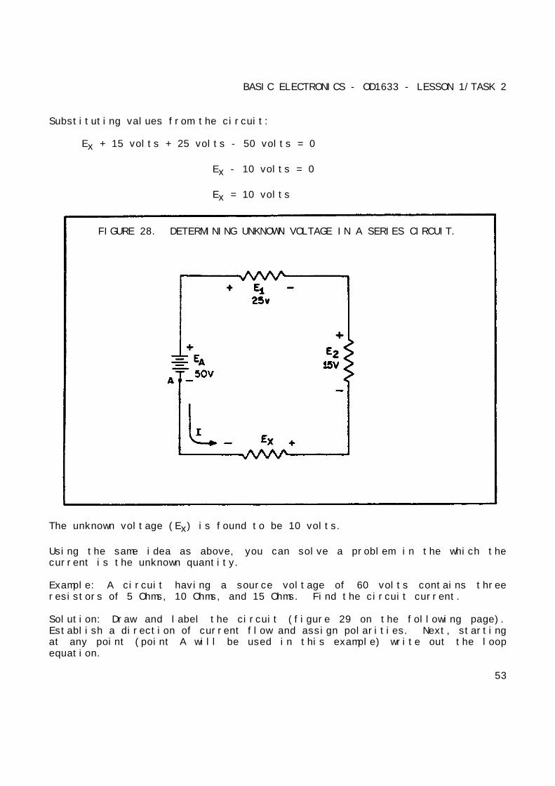
Example: Three resistors are connected across a 50 volt source. What is thevoltage across the third resistor if the voltage drops across the first tworesistors are 25 volts and 15 volts?
Solution: First, a diagram (such as figure 28 on the following page) isdrawn. Next, a direction of current is assumed (as shown). Using thiscurrent, the polarity markings are placed at each end of each resistor andalso on the terminals of the source. Starting at point A, trace around thecircuit in the direction of current flow, recording the voltage and polarityof each component. Starting at point A and using the components from thecircuit:
(+Ex) + (+E2) + (+E1) + (-EA) = 0
52
BASIC ELECTRONICS - OD1633 - LESSON 1/TASK 2
Substituting values from the circuit:
Ex + 15 volts + 25 volts - 50 volts = 0
Ex - 10 volts = 0
Ex = 10 volts
FIGURE 28. DETERMINING UNKNOWN VOLTAGE IN A SERIES CIRCUIT.
The unknown voltage (Ex) is found to be 10 volts.
Using the same idea as above, you can solve a problem in the which thecurrent is the unknown quantity.
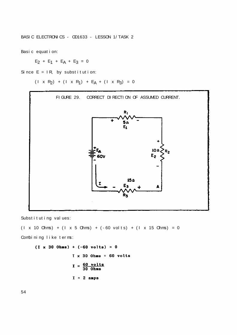
Example: A circuit having a source voltage of 60 volts contains threeresistors of 5 Ohms, 10 Ohms, and 15 Ohms. Find the circuit current.
Solution: Draw and label the circuit (figure 29 on the following page).Establish a direction of current flow and assign polarities. Next, startingat any point (point A will be used in this example) write out the loopequation.
53
BASIC ELECTRONICS - OD1633 - LESSON 1/TASK 2
Basic equation:
E2 + E1 + EA + E3 = 0
Since E = IR, by substitution:
(I x R2) + (I x R1) + EA + (I x R3) = 0
FIGURE 29. CORRECT DIRECTION OF ASSUMED CURRENT.
Substituting values:
(I x 10 Ohms) + (I x 5 Ohms) + (-60 volts) + (I x 15 Ohms) = 0
Combining like terms:
54
BASIC ELECTRONICS - OD1633 - LESSON 1/TASK 2
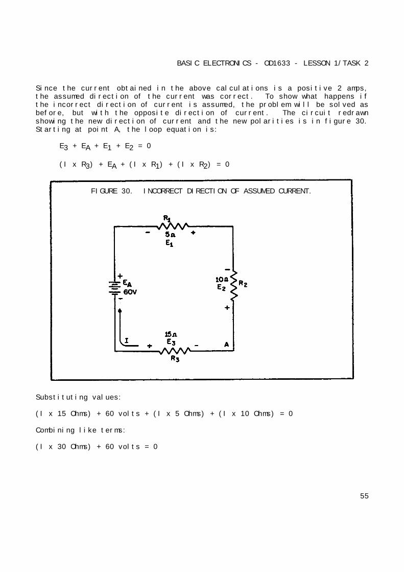
Since the current obtained in the above calculations is a positive 2 amps,the assumed direction of the current was correct. To show what happens ifthe incorrect direction of current is assumed, the problem will be solved asbefore, but with the opposite direction of current. The circuit redrawnshowing the new direction of current and the new polarities is in figure 30.Starting at point A, the loop equation is:
E3 + EA + E1 + E2 = 0
(I x R3) + EA + (I x R1) + (I x R2) = 0
FIGURE 30. INCORRECT DIRECTION OF ASSUMED CURRENT.
Substituting values:
(I x 15 Ohms) + 60 volts + (I x 5 Ohms) + (I x 10 Ohms) = 0
Combining like terms:
(I x 30 Ohms) + 60 volts = 0
55

BASIC ELECTRONICS - OD1633 - LESSON 1/TASK 2
Notice that the amount of current is the same as before. The polarity,however, is negative. The negative polarity simply indicates the wrongdirection of current was assumed. Should it be necessary to use thiscurrent in further calculations on the circuit using Kirchhoff's law, thenegative polarity should be retained in the calculations.
(2) Series Aiding and Opposing Sources. In many practicalapplications, a circuit may contain more than one source of EMF. Sources ofEMF that cause current to flow in the same direction are considered to beseries aiding and the voltages are added. Sources of EMF that would tend toforce current in opposite directions are said to be series opposing, and theeffective source of voltage is the difference between the opposing
FIGURE 31. AIDING AND OPPOSING SOURCES.
56

BASIC ELECTRONICS - OD1633 - LESSON 1/TASK
voltages. When two opposing sources are inserted into a circuit, currentflow would be in a direction determined by the larger source.
Examples of series aiding and opposing sources are shown in figure 31 on theprevious page.
A simple solution may be obtained for a multiple-source circuit through theuse of Kirchhoff's voltage law. In applying this method, the same procedureis used for the multiple-source circuit as was used above for the single-source circuit. This is demonstrated by the following.
Example: Using Kirchhoff's voltage equation, find the amount of current inthe circuit shown in figure 32.
FIGURE 32. SOLVING FOR CIRCUIT CURRENT USING KIRCHHOFF'S VOLTAGECURRENT.
Solution: As before, a direction of current flow is assumed and polaritysigns are placed on the drawing. The loop equation will be started at pointA.
E2 + ER1 + E1 + E3 + ER2 = 0
57
BASIC ELECTRONICS - OD1633 - LESSON 1/TASK 2
20 volts + (I x 60 Ohms) + (-180 volts) + 40 volts + (I x 20 Ohms) = 0
20 volts - 180 volts + 40 volts 4 (C x 60 Ohms) + (I x 20 Ohms) = 0
-120 volts + (I x 80 Ohms) = 0
I x 80 Ohms = 120 volts
I = 1.5 amps
4. Circuit Terms and Characteristics
Before you learn about the type of circuits other than the series circuit,you should become familiar with some of the terms and characteristics usedin electrical circuits. These terms and characteristics will be usedthroughout your study of electricity and electronics.
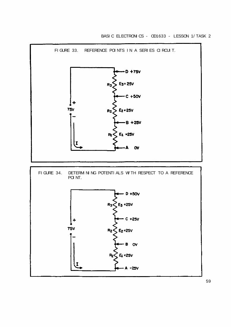
a. Reference Point. A reference point is an arbitrarily chosen pointto which all other points in the circuit are compared. In series circuits,any point can be chosen as a reference and the electrical potential at allother points can be determined in reference to that point. In figure 33, onthe following page, point A should be considered the reference point. Eachseries resistor in the illustrated circuit is of equal value. The appliedvoltage is equally distributed across each resistor. The potential at pointB is 25 volts more positive than at point A. Points C and D are 50 voltsand 75 volts, more positive than point A respectively.
When point B is used as the reference, as in figure 34 on the followingpage, point D would be positive 50 volts in respect to the new referencepoint. The former reference point A, is 25 volts negative in respect topoint B.
As in the previous circuit illustration, the reference point of a circuit isalways considered to be at zero potential. Since the earth (ground) is saidto be at a zero potential, the term ground is used to denote a commonelectrical point of zero potential. In figure 35, on page 60, point A isthe zero reference, or ground, and the symbol for
58
BASIC ELECTRONICS - OD1633 - LESSON 1/TASK 2
FIGURE 33. REFERENCE POINTS IN A SERIES CIRCUIT.
FIGURE 34. DETERMINING POTENTIALS WITH RESPECT TO A REFERENCEPOINT.
59

BASIC ELECTRONICS - OD1633 - LESSON 1/TASK 2
FIGURE 35. USE OF GROUND SYMBOLS.
ground is shown connected to point A. Point C is 75 volts positive inrespect to ground.
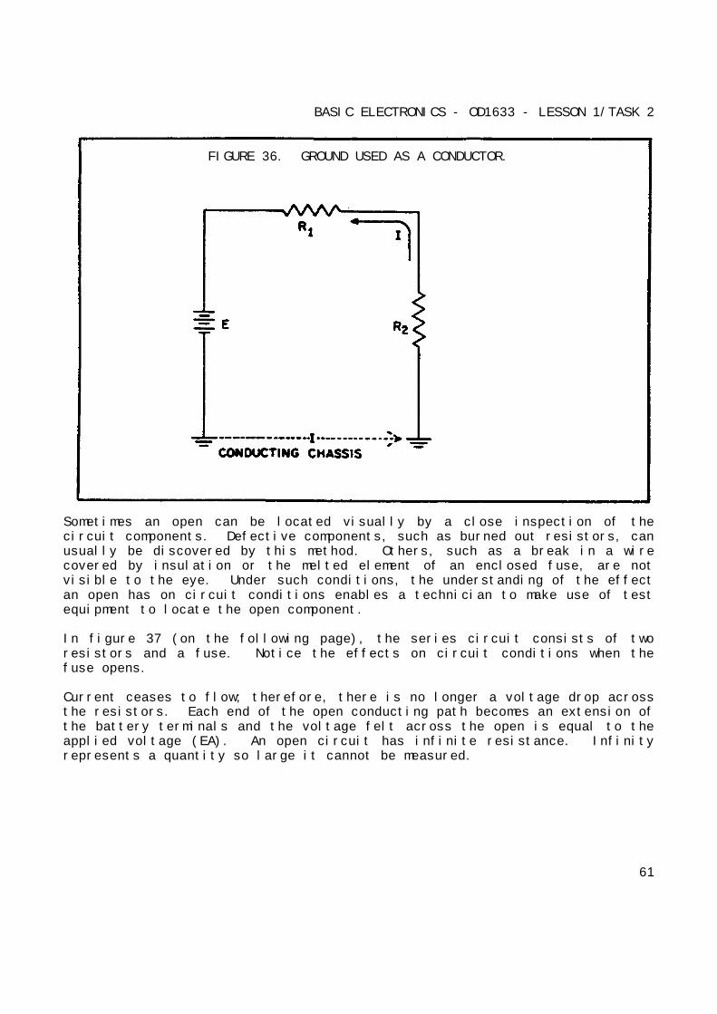
In most electrical equipment, the metal chassis is the common ground for themany electrical circuits. When each electrical circuit is completed, commonpoints of a circuit at zero potential are connected directly to the metalchassis, thereby eliminating a large amount of connecting wire. Theelectrons pass through the metal chassis (a conductor) to reach other pointsof the circuit. An example of a chassis grounded circuit is illustrated infigure 36 on the following page.
Most voltage measurements used to check proper circuit operation inelectrical equipment are taken in respect to ground. One meter lead isattached to a grounded point and the other meter lead is moved to varioustest points.
b. Open Circuit. A circuit is said to be open when a break exists in acomplete conducting pathway. Although an open occurs when a switch is usedto deenergize a circuit, an open may also develop accidentally. To restorea circuit to proper operation, the open must be located, its causedetermined, and repairs made.
60
BASIC ELECTRONICS - OD1633 - LESSON 1/TASK 2
FIGURE 36. GROUND USED AS A CONDUCTOR.
Sometimes an open can be located visually by a close inspection of thecircuit components. Defective components, such as burned out resistors, canusually be discovered by this method. Others, such as a break in a wirecovered by insulation or the melted element of an enclosed fuse, are notvisible to the eye. Under such conditions, the understanding of the effectan open has on circuit conditions enables a technician to make use of testequipment to locate the open component.
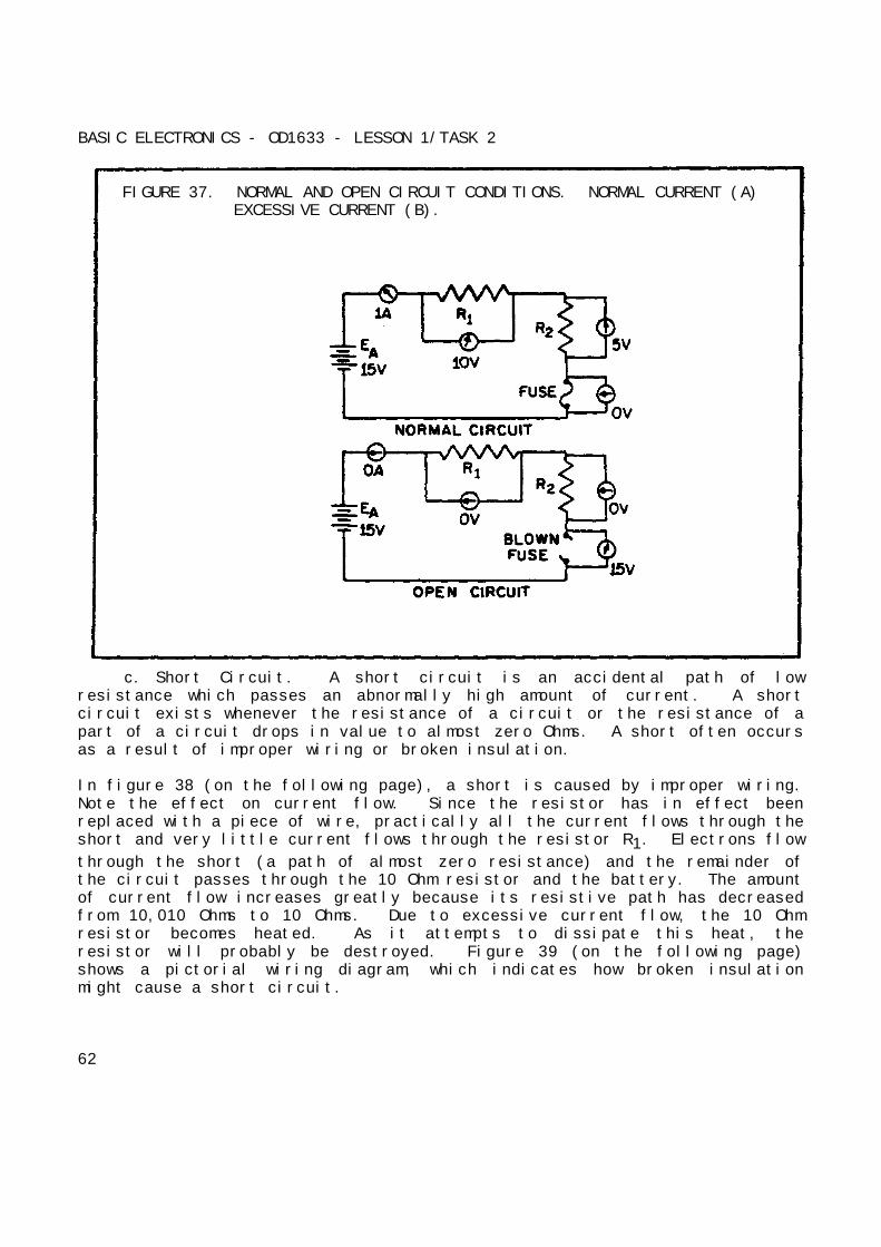
In figure 37 (on the following page), the series circuit consists of tworesistors and a fuse. Notice the effects on circuit conditions when thefuse opens.
Current ceases to flow; therefore, there is no longer a voltage drop acrossthe resistors. Each end of the open conducting path becomes an extension ofthe battery terminals and the voltage felt across the open is equal to theapplied voltage (EA). An open circuit has infinite resistance. Infinityrepresents a quantity so large it cannot be measured.
61
BASIC ELECTRONICS - OD1633 - LESSON 1/TASK 2
FIGURE 37. NORMAL AND OPEN CIRCUIT CONDITIONS. NORMAL CURRENT (A)EXCESSIVE CURRENT (B).
c. Short Circuit. A short circuit is an accidental path of lowresistance which passes an abnormally high amount of current. A shortcircuit exists whenever the resistance of a circuit or the resistance of apart of a circuit drops in value to almost zero Ohms. A short often occursas a result of improper wiring or broken insulation.
In figure 38 (on the following page), a short is caused by improper wiring.Note the effect on current flow. Since the resistor has in effect beenreplaced with a piece of wire, practically all the current flows through theshort and very little current flows through the resistor R1. Electrons flow
through the short (a path of almost zero resistance) and the remainder ofthe circuit passes through the 10 Ohm resistor and the battery. The amountof current flow increases greatly because its resistive path has decreasedfrom 10,010 Ohms to 10 Ohms. Due to excessive current flow, the 10 Ohmresistor becomes heated. As it attempts to dissipate this heat, theresistor will probably be destroyed. Figure 39 (on the following page)shows a pictorial wiring diagram, which indicates how broken insulationmight cause a short circuit.
62
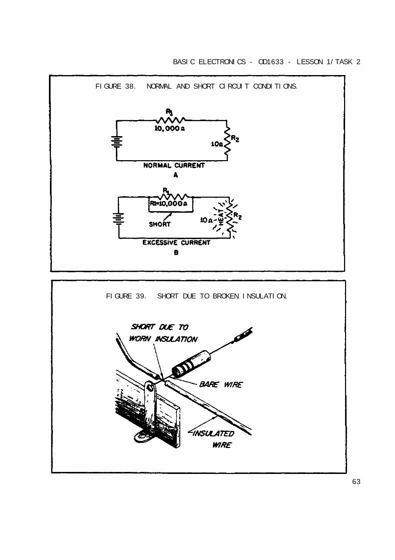
BASIC ELECTRONICS - OD1633 - LESSON 1/TASK 2
FIGURE 38. NORMAL AND SHORT CIRCUIT CONDITIONS.
FIGURE 39. SHORT DUE TO BROKEN INSULATION.
63
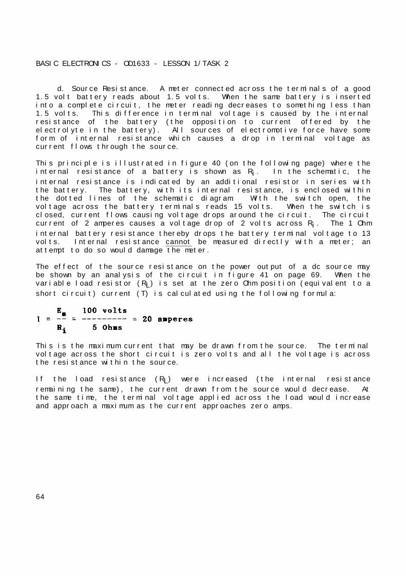
BASIC ELECTRONICS - OD1633 - LESSON 1/TASK 2
d. Source Resistance. A meter connected across the terminals of a good1.5 volt battery reads about 1.5 volts. When the same battery is insertedinto a complete circuit, the meter reading decreases to something less than1.5 volts. This difference in terminal voltage is caused by the internalresistance of the battery (the opposition to current offered by theelectrolyte in the battery). All sources of electromotive force have someform of internal resistance which causes a drop in terminal voltage ascurrent flows through the source.
This principle is illustrated in figure 40 (on the following page) where theinternal resistance of a battery is shown as Ri. In the schematic, the
internal resistance is indicated by an additional resistor in series withthe battery. The battery, with its internal resistance, is enclosed withinthe dotted lines of the schematic diagram. With the switch open, thevoltage across the battery terminals reads 15 volts. When the switch isclosed, current flows causing voltage drops around the circuit. The circuitcurrent of 2 amperes causes a voltage drop of 2 volts across Ri. The 1 Ohm
internal battery resistance thereby drops the battery terminal voltage to 13volts. Internal resistance cannot be measured directly with a meter; anattempt to do so would damage the meter.
The effect of the source resistance on the power output of a dc source maybe shown by an analysis of the circuit in figure 41 on page 69. When thevariable load resistor (RL) is set at the zero Ohm position (equivalent to a
short circuit) current (T) is calculated using the following formula:
This is the maximum current that may be drawn from the source. The terminalvoltage across the short circuit is zero volts and all the voltage is acrossthe resistance within the source.
If the load resistance (RL) were increased (the internal resistance
remaining the same), the current drawn from the source would decrease. Atthe same time, the terminal voltage applied across the load would increaseand approach a maximum as the current approaches zero amps.
64
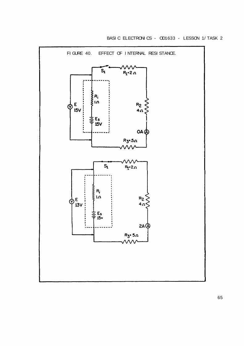
BASIC ELECTRONICS - OD1633 - LESSON 1/TASK 2
FIGURE 40. EFFECT OF INTERNAL RESISTANCE.
65

BASIC ELECTRONICS - OD1633 - LESSON 1/TASK 2
FIGURE 41. EFFECT OF SOURCE RESISTANCE ON POWER OUTPUT.
66

BASIC ELECTRONICS - OD1633 - LESSON 1/TASK 2
e. Power Transfer and Efficiency. Maximum power is transferred fromthe source to the load when the resistance of the load is equal to theinternal resistance of the source. This theory is illustrated in the tableand the graph of figure 41 (on the previous page). When the load resistanceis 5 Ohms, matching the source resistance, the maximum power of 500 watts isdeveloped in the load.
The efficiency of power transfer (ratio of output power to input power) fromthe source to the load increases as the load resistance is increased. Theefficiency approaches 100 percent as the load resistance approaches arelatively large value compared with that of the source, since less power islost in the source. The efficiency of power transfer is only 50 percent atthe maximum power transfer point (when the load resistance equals theinternal resistance of the source). The efficiency of power transferapproaches zero efficiency when the load resistance is relatively smallcompared with the internal resistance of the source. This is also shown onthe chart of figure 41 on the previous page.
The problem of a desire for both high efficiency and maximum power transferis resolved by a compromise between maximum power transfer and highefficiency. Where the amounts of power involved are large and theefficiency is important, the load resistance is made large relative to thesource resistance so that the losses are kept small. In this case, theefficiency is high. Where the problem of matching a source to a load isimportant, as in communications circuits, a strong signal may be moreimportant than a high percentage of efficiency. In such cases, theefficiency of power transfer should be only about 50 percent; however, thepower transfer would be the maximum which the source is capable ofsupplying.
You should now understand the basic concepts of series circuits. Theprinciples which have been presented are of lasting importance. Onceequipped with a firm understanding of series circuits, you hold the key toan understanding of the parallel circuits to be presented next.
67
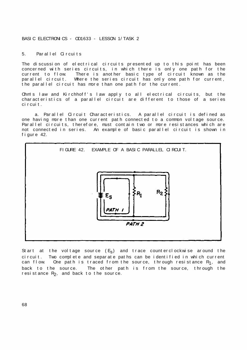
BASIC ELECTRONICS - OD1633 - LESSON 1/TASK 2
5. Parallel Circuits
The discussion of electrical circuits presented up to this point has beenconcerned with series circuits, in which there is only one path for thecurrent to flow. There is another basic type of circuit known as theparallel circuit. Where the series circuit has only one path for current,the parallel circuit has more than one path for the current.
Ohm's law and Kirchhoff's law apply to all electrical circuits, but thecharacteristics of a parallel circuit are different to those of a seriescircuit.
a. Parallel Circuit Characteristics. A parallel circuit is defined asone having more than one current path connected to a common voltage source.Parallel circuits, therefore, must contain two or more resistances which arenot connected in series. An example of basic parallel circuit is shown infigure 42.
FIGURE 42. EXAMPLE OF A BASIC PARALLEL CIRCUIT.
Start at the voltage source (Es) and trace counterclockwise around the
circuit. Two complete and separate paths can be identified in which currentcan flow. One path is traced from the source, through resistance R1, and
back to the source. The other path is from the source, through theresistance R2, and back to the source.
68
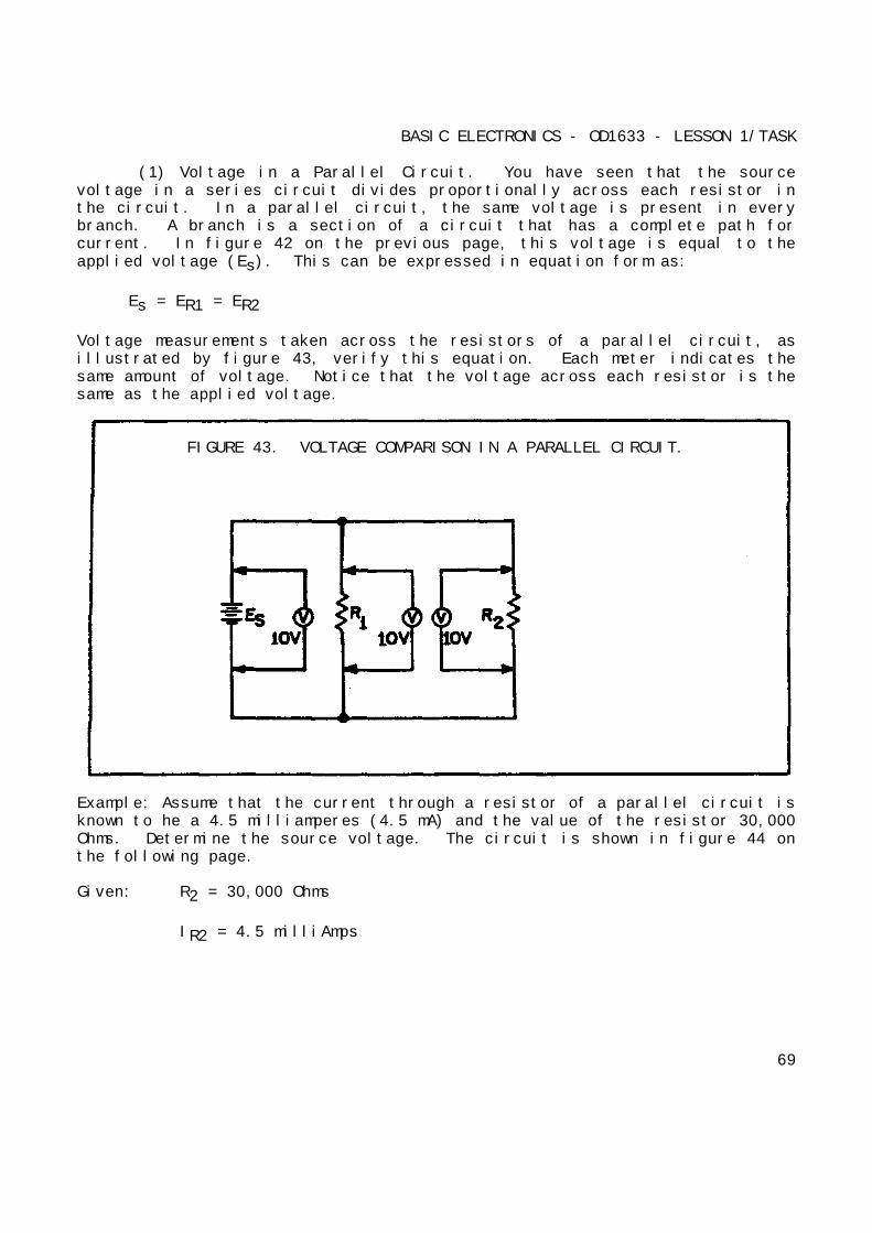
BASIC ELECTRONICS - OD1633 - LESSON 1/TASK
(1) Voltage in a Parallel Circuit. You have seen that the sourcevoltage in a series circuit divides proportionally across each resistor inthe circuit. In a parallel circuit, the same voltage is present in everybranch. A branch is a section of a circuit that has a complete path forcurrent. In figure 42 on the previous page, this voltage is equal to theapplied voltage (Es). This can be expressed in equation form as:
Es = ER1 = ER2
Voltage measurements taken across the resistors of a parallel circuit, asillustrated by figure 43, verify this equation. Each meter indicates thesame amount of voltage. Notice that the voltage across each resistor is thesame as the applied voltage.
FIGURE 43. VOLTAGE COMPARISON IN A PARALLEL CIRCUIT.
Example: Assume that the current through a resistor of a parallel circuit isknown to he a 4.5 milliamperes (4.5 mA) and the value of the resistor 30,000Ohms. Determine the source voltage. The circuit is shown in figure 44 onthe following page.
Given: R2 = 30,000 Ohms
IR2 = 4.5 milliAmps
69

BASIC ELECTRONICS - OD1633 - LESSON 1/TASK 2
FIGURE 44. EXAMPLE PROBLEM PARALLEL CIRCUIT.
Solution: E = IR
ER2 = .0045 amps x 30,000 Ohms
ER2 = 135 volts
Since the source voltage is equal to the voltage of a branch:
Es = ER2
Es = 135 volts
To simplify the math operation, the values can be expressed in powers of tenas follows:
30,000 Ohms = 30 x 103 Ohms
4.5 mA = 4.5 x 10⁻³ amps
ER2 = (4.5 x 30 x 10-3 x 103) volts
(10-3 x 103 = 10-3 + 3 = 100 = 1)
ER2 = (4.5 x 30 x 1) volts
ER2 = 135 volts
Es = R2
Es = 135 volts
70
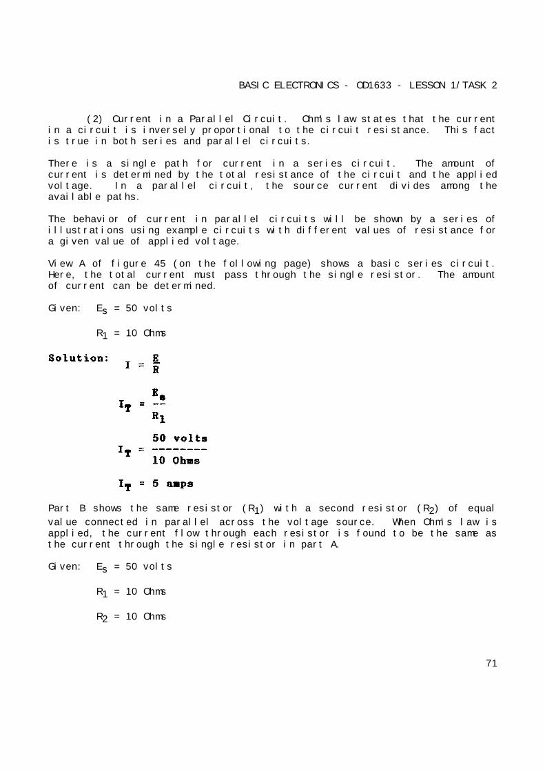
BASIC ELECTRONICS - OD1633 - LESSON 1/TASK 2
(2) Current in a Parallel Circuit. Ohm's law states that the currentin a circuit is inversely proportional to the circuit resistance. This factis true in both series and parallel circuits.
There is a single path for current in a series circuit. The amount ofcurrent is determined by the total resistance of the circuit and the appliedvoltage. In a parallel circuit, the source current divides among theavailable paths.
The behavior of current in parallel circuits will be shown by a series ofillustrations using example circuits with different values of resistance fora given value of applied voltage.
View A of figure 45 (on the following page) shows a basic series circuit.Here, the total current must pass through the single resistor. The amountof current can be determined.
Given: Es = 50 volts
R1 = 10 Ohms
Part B shows the same resistor (R1) with a second resistor (R2) of equal
value connected in parallel across the voltage source. When Ohm's law isapplied, the current flow through each resistor is found to be the same asthe current through the single resistor in part A.
Given: Es = 50 volts
R1 = 10 Ohms
R2 = 10 Ohms
71
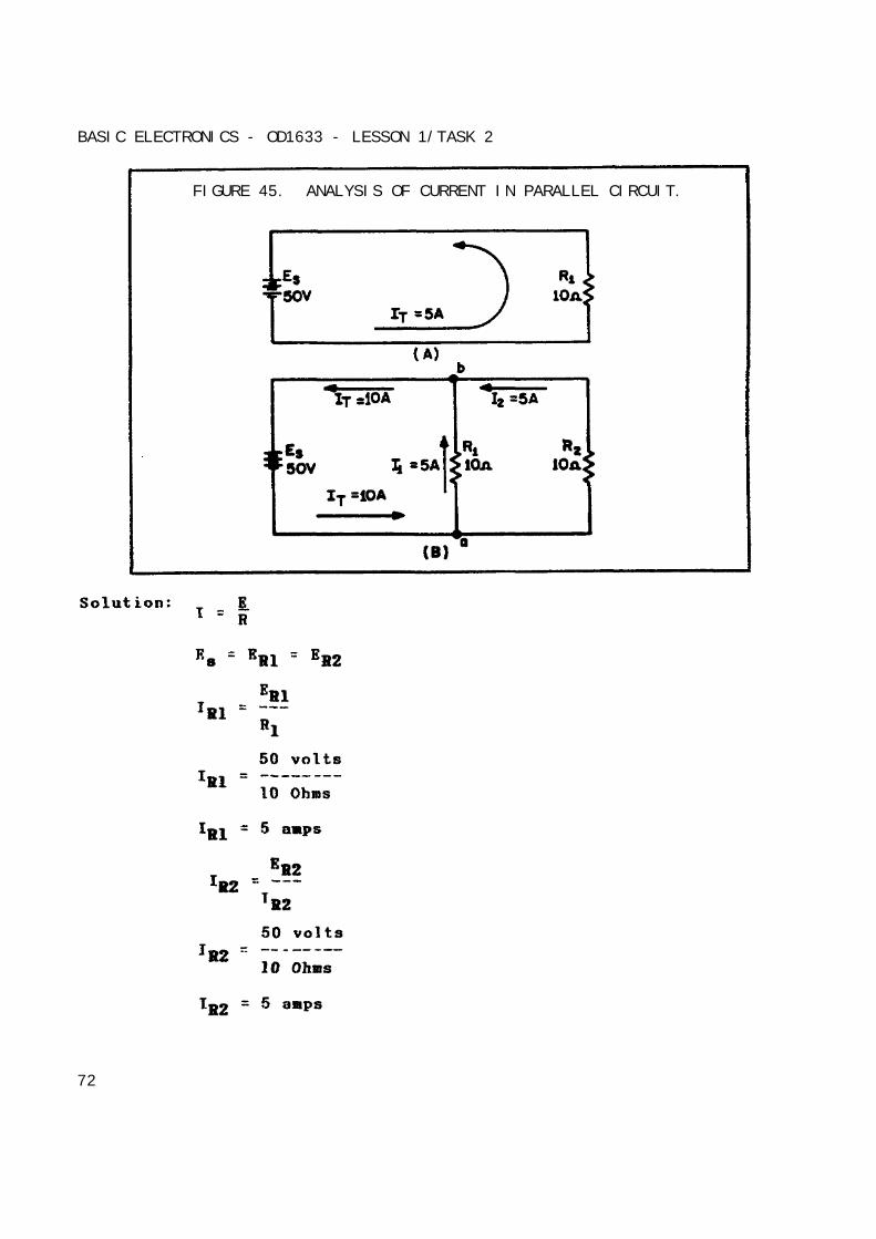
BASIC ELECTRONICS - OD1633 - LESSON 1/TASK 2
FIGURE 45. ANALYSIS OF CURRENT IN PARALLEL CIRCUIT.
72
BASIC ELECTRONICS - OD1633 - LESSON 1/TASK
It is apparent that if there are 5 amperes of current through each of thetwo resistors, there must be a total current of 10 amperes drawn from thesource.
The total current of 10 amperes, as illustrated in figure 45, view B on theprevious page, leaves the negative terminal of the battery and flows topoint a. Since point a is a connecting point for the two resistors, it ispalled a junction. At junction a, the total current divides into twocurrents of 5 amperes each. These two currents flow through their resistorsand rejoin at junction b. The total current then flows from junction b backto the positive terminal of the source. The source supplies a total currentof 10 amperes and each of the two equal resistors carries one-half of thetotal current.
Each individual current path in the circuit of figure 45 (view B) isreferred to as a branch. Each branch carries a current that is a portion ofthe total current. Two or more branches form a network.
From the previous explanation, the characteristics of current in a parallelcircuit can be expressed in terms of the following general equation:
IT = I1 + I2 + I3 + ... In
Compare view A of figure 46 (on the following page) with view B of thecircuit in figure 45. Notice that doubling the value of the second branchresistor (R2) has no effect on the current in the first branch (IR1), but
does reduce the second branch current (IR2) to one-half its original value.
The total circuit current drops to a value equal to the sum of the branchcurrents. These facts are verified by the following equations.
Given: Es = 50 volts
R1 = 10 Ohms
R2 = 20 Ohms
73
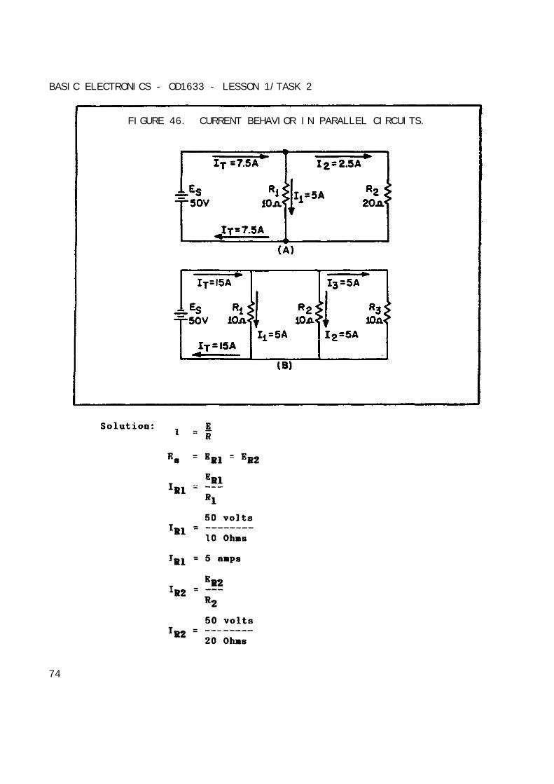
BASIC ELECTRONICS - OD1633 - LESSON 1/TASK 2
FIGURE 46. CURRENT BEHAVIOR IN PARALLEL CIRCUITS.
74
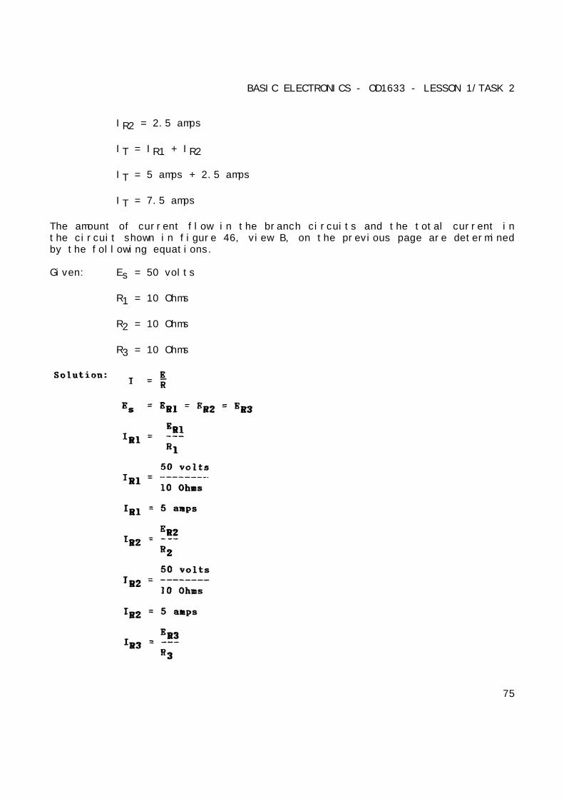
BASIC ELECTRONICS - OD1633 - LESSON 1/TASK 2
IR2 = 2.5 amps
IT = IR1 + IR2
IT = 5 amps + 2.5 amps
IT = 7.5 amps
The amount of current flow in the branch circuits and the total current inthe circuit shown in figure 46, view B, on the previous page are determinedby the following equations.
Given: Es = 50 volts
R1 = 10 Ohms
R2 = 10 Ohms
R3 = 10 Ohms
75

BASIC ELECTRONICS - OD1633 - LESSON 1/TASK 2
Notice that the sum of the ohmic values of the resistors in both circuitsshown in figure 46 on page 77 is equal (30 Ohms), and that the appliedvoltage is the same value (50 volts). However, the total current in figure44, view B, on page 73, (15 amps) is twice the amount in figure 44, view A(7.5 amps). It is apparent, therefore, that the manner in which resistorsare connected in a circuit, as well as their actual ohmic values, affect thetotal current.
The division of current in a parallel network follows a definite pattern.This pattern is described by Kirchhoff's law which states:
"The algebraic sum of the currents entering and leaving any junction ofconductors is equal to zero."
This law can be stated mathematically as:
Ia + Ib + ... In = 0
where Ia, Ib, etc., are the currents entering and leaving the junction.
Currents entering the junction are considered to be positive and currentsleaving the junction are considered to be negative. When solving a problemusing Kirchhoff's law, the currents must be placed into the equation withthe proper polarity signs attached.
Example: Solve for the value of 13 in figure 47 on the following page.
Given: I1 = 10 amps
I2 = 3 amps
I4 = 5 amps
76
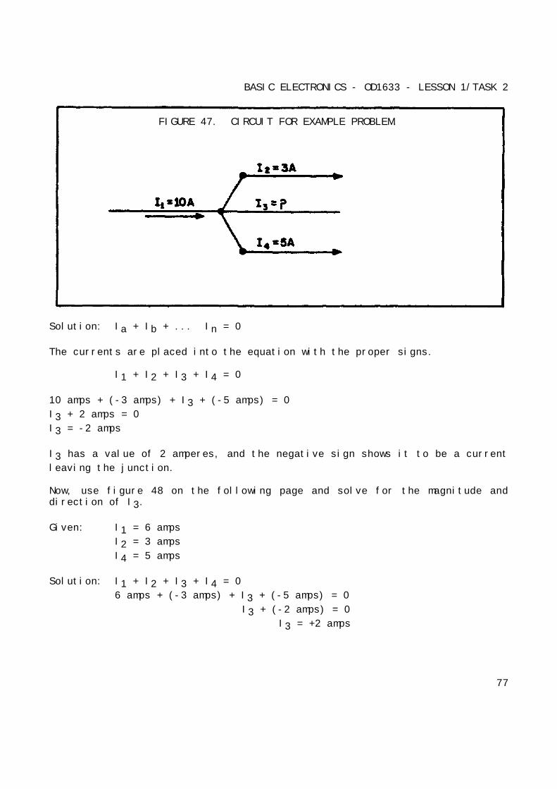
BASIC ELECTRONICS - OD1633 - LESSON 1/TASK 2
FIGURE 47. CIRCUIT FOR EXAMPLE PROBLEM.
Solution: Ia + Ib + ... In = 0
The currents are placed into the equation with the proper signs.
I1 + I2 + I3 + I4 = 0
10 amps + (-3 amps) + I3 + (-5 amps) = 0
I3 + 2 amps = 0
I3 = -2 amps
I3 has a value of 2 amperes, and the negative sign shows it to be a current
leaving the junction.
Now, use figure 48 on the following page and solve for the magnitude anddirection of I3.
Given: I1 = 6 amps
I2 = 3 amps
I4 = 5 amps
Solution: I1 + I2 + I3 + I4 = 0
6 amps + (-3 amps) + I3 + (-5 amps) = 0
I3 + (-2 amps) = 0
I3 = +2 amps
77
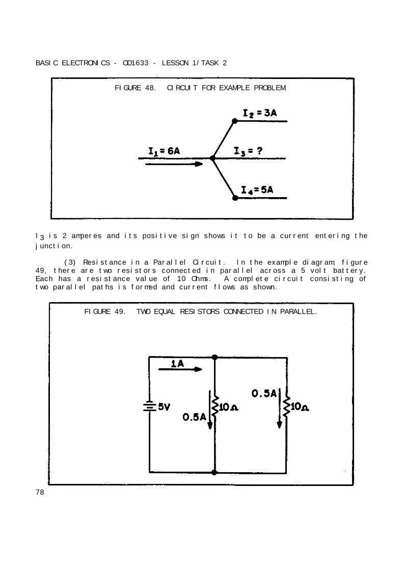
BASIC ELECTRONICS - OD1633 - LESSON 1/TASK 2
FIGURE 48. CIRCUIT FOR EXAMPLE PROBLEM.
I3 is 2 amperes and its positive sign shows it to be a current entering the
junction.
(3) Resistance in a Parallel Circuit. In the example diagram, figure49, there are two resistors connected in parallel across a 5 volt battery.Each has a resistance value of 10 Ohms. A complete circuit consisting oftwo parallel paths is formed and current flows as shown.
FIGURE 49. TWO EQUAL RESISTORS CONNECTED IN PARALLEL.
78
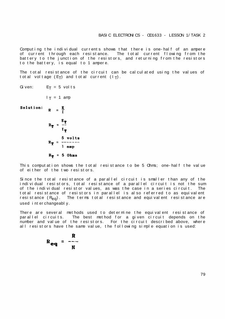
BASIC ELECTRONICS - OD1633 - LESSON 1/TASK 2
Computing the individual currents shows that there is one-half of an ampereof current through each resistance. The total current flowing from thebattery to the junction of the resistors, and returning from the resistorsto the battery, is equal to 1 ampere.
The total resistance of the circuit can be calculated using the values oftotal voltage (ET) and total current (IT).
Given: ET = 5 volts
IT = 1 amp
This computation shows the total resistance to be 5 Ohms; one-half the valueof either of the two resistors.
Since the total resistance of a parallel circuit is smaller than any of theindividual resistors, total resistance of a parallel circuit is not the sumof the individual resistor values, as was the case in a series circuit. Thetotal resistance of resistors in parallel is also referred to as equivalentresistance (Req). The terms total resistance and equivalent resistance are
used interchangeably.
There are several methods used to determine the equivalent resistance ofparallel circuits. The best method for a given circuit depends on thenumber and value of the resistors. For the circuit described above, whereall resistors have the same value, the following simple equation is used:
79

BASIC ELECTRONICS - OD1633 - LESSON 1/TASK 2
Where: Req = equivalent parallel resistance
R = ohmic value of one resistor
N = number of resistors
This equation is valid for any number of parallel resistors of equal value.
Example: Four 40 Ohm resistors are connected in parallel. What is theirequivalent resistance?
Given: R1 = R2 = R3 = R4
R1 = 40 Ohms
Figure 50 shows two resistors of unequal value in parallel. Since the totalcurrent is shown, the equivalent resistance can be calculated.
FIGURE 50. EXAMPLE OF CIRCUIT WITH UNEQUAL PARALLEL RESISTORS.
80
BASIC ELECTRONICS - OD1633 - LESSON 1/TASK 2
Given: Es = 30 volts
IT = 15 amps
The equivalent resistance of the circuit shown in figure 50 on the previouspage is smaller than either of the two resistors (R1, R2). A point to
remember is that the equivalent resistance of a parallel circuit is alwaysless than the resistance of any branch.
Equivalent resistance can be found if you know the individual resistancevalues and the source voltage. By calculating each branch current, addingthe branch currents to calculate total current, and dividing the sourcevoltage by the total current, the total can be found. This method, whileeffective, is somewhat lengthy. A quicker method of finding equivalentresistance is to use the general formula for resistors in parallel:
If you apply the general formula to the circuit shown in figure 50, you willget the same value for equivalent resistance (2 Ohms) as was obtained in theprevious calculation that used source voltage and total current.
Given: R1 = 3 Ohms
R2 = 6 Ohms
81
BASIC ELECTRONICS - OD1633 - LESSON 1/TASK 2
Convert the fractions to a common denominator.
Since both sides are reciprocals (each divided is into owe), disregard thereciprocal function.
The formula for equal resistors in parallel, is a simplification
of the general formula for resistors in parallel. There are othersimplifications of the general formula for resistors in parallel which canbe used to calculate the total or equivalent resistance in a parallelcircuit.
(a) Reciprocal Method. This method is based upon taking thereciprocal of each side of the equation. This presents the general formulafor resistors in parallel as:
This formula is used to solve for the equivalent resistance of a number ofunequal parallel resistors. You must find the lowest common denominator insolving these problems.
Example: Three resistors are connected in parallel as shown in figure 51 (onthe following page). The resistor values are: R1 = 20 Ohms, R2 = 30 Ohms,
R3 = 40 Ohms. Using the reciprocal method, what is the equivalent
resistance?
82
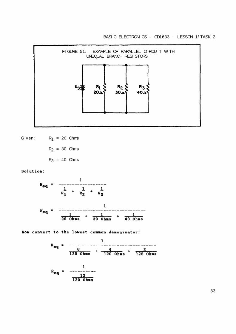
BASIC ELECTRONICS - OD1633 - LESSON 1/TASK 2
FIGURE 51. EXAMPLE OF PARALLEL CIRCUIT WITHUNEQUAL BRANCH RESISTORS.
Given: R1 = 20 Ohms
R2 = 30 Ohms
R3 = 40 Ohms
83
BASIC ELECTRONICS - OD1633 - LESSON 1/TASK 2
(b) Product Over the Sum Method. A convenient method for findingthe equivalent, or total, resistance of two parallel resistors is by usingthe following formula:
This equation, called the product over the sum formula, is used sofrequently it should be committed to memory.
Example: What is the equivalent resistance of a 20 Ohm and a 30 Ohm resistorconnected in parallel, as in figure 52 on the following page.
Given: R1 = 20 Ohms
R2 = 30 Ohms
(4) Power in a Parallel Circuit. Power computations in a parallelcircuit are essentially the same as those used for the series circuit.Since power dissipation in resistors consists of heat loss, powerdissipations are additive, regardless of how the resistors are connected inthe circuit. The total power is equal to the sum
84
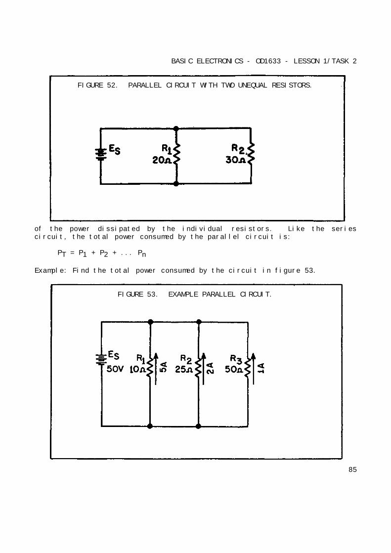
BASIC ELECTRONICS - OD1633 - LESSON 1/TASK 2
FIGURE 52. PARALLEL CIRCUIT WITH TWO UNEQUAL RESISTORS.
of the power dissipated by the individual resistors. Like the seriescircuit, the total power consumed by the parallel circuit is:
PT = P1 + P2 + ... Pn
Example: Find the total power consumed by the circuit in figure 53.
FIGURE 53. EXAMPLE PARALLEL CIRCUIT.
85
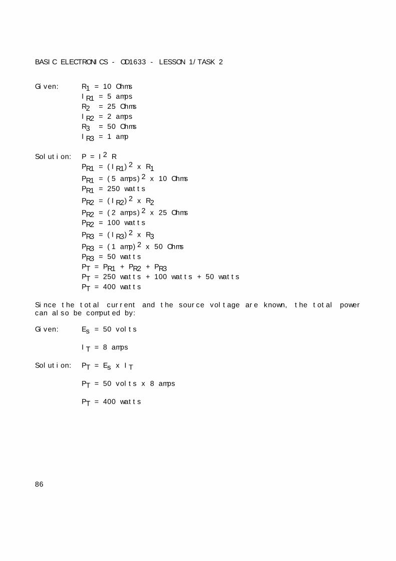
BASIC ELECTRONICS - OD1633 - LESSON 1/TASK 2
Given: R1 = 10 Ohms
IR1 = 5 amps
R2 = 25 Ohms
IR2 = 2 amps
R3 = 50 Ohms
IR3 = 1 amp
Solution: P = I2 R
PR1 = (IR1)2 x R1
PR1 = (5 amps)2 x 10 Ohms
PR1 = 250 watts
PR2 = (IR2)2 x R2
PR2 = (2 amps)2 x 25 Ohms
PR2 = 100 watts
PR3 = (IR3)2 x R3
PR3 = (1 amp)2 x 50 Ohms
PR3 = 50 watts
PT = PR1 + PR2 + PR3PT = 250 watts + 100 watts + 50 watts
PT = 400 watts
Since the total current and the source voltage are known, the total powercan also be computed by:
Given: Es = 50 volts
IT = 8 amps
Solution: PT = Es x IT
PT = 50 volts x 8 amps
PT = 400 watts
86
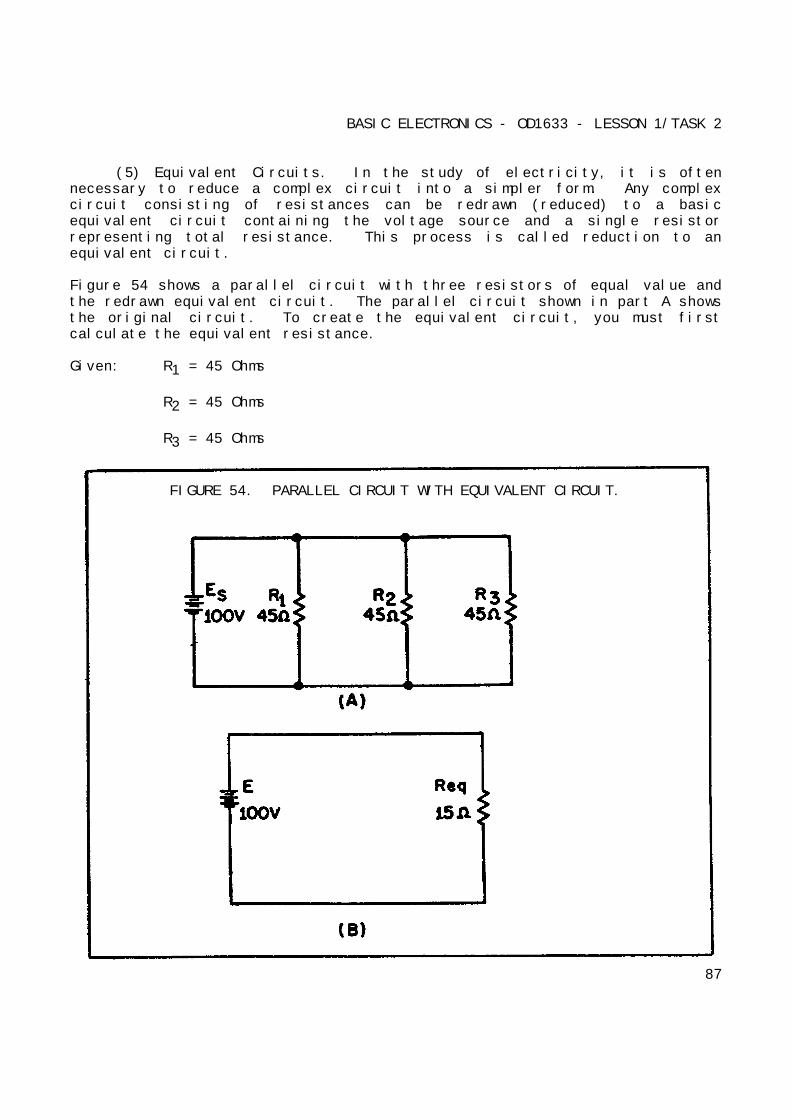
BASIC ELECTRONICS - OD1633 - LESSON 1/TASK 2
(5) Equivalent Circuits. In the study of electricity, it is oftennecessary to reduce a complex circuit into a simpler form. Any complexcircuit consisting of resistances can be redrawn (reduced) to a basicequivalent circuit containing the voltage source and a single resistorrepresenting total resistance. This process is called reduction to anequivalent circuit.
Figure 54 shows a parallel circuit with three resistors of equal value andthe redrawn equivalent circuit. The parallel circuit shown in part A showsthe original circuit. To create the equivalent circuit, you must firstcalculate the equivalent resistance.
Given: R1 = 45 Ohms
R2 = 45 Ohms
R3 = 45 Ohms
FIGURE 54. PARALLEL CIRCUIT WITH EQUIVALENT CIRCUIT.
87
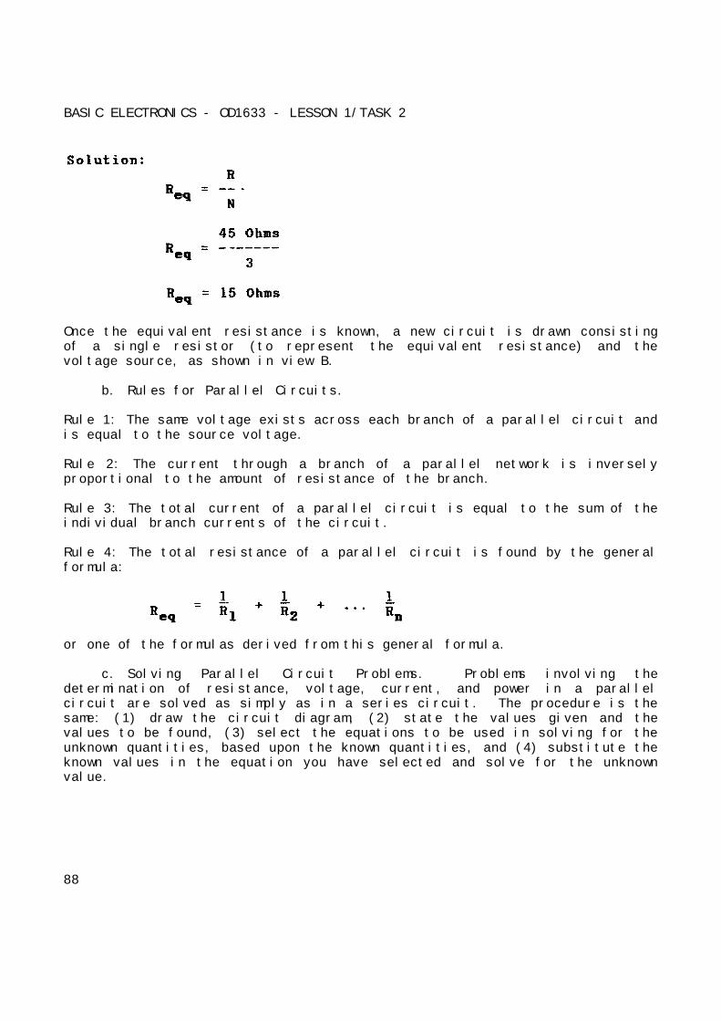
BASIC ELECTRONICS - OD1633 - LESSON 1/TASK 2
Once the equivalent resistance is known, a new circuit is drawn consistingof a single resistor (to represent the equivalent resistance) and thevoltage source, as shown in view B.
b. Rules for Parallel Circuits.
Rule 1: The same voltage exists across each branch of a parallel circuit andis equal to the source voltage.
Rule 2: The current through a branch of a parallel network is inverselyproportional to the amount of resistance of the branch.
Rule 3: The total current of a parallel circuit is equal to the sum of theindividual branch currents of the circuit.
Rule 4: The total resistance of a parallel circuit is found by the generalformula:
or one of the formulas derived from this general formula.
c. Solving Parallel Circuit Problems. Problems involving thedetermination of resistance, voltage, current, and power in a parallelcircuit are solved as simply as in a series circuit. The procedure is thesame: (1) draw the circuit diagram, (2) state the values given and thevalues to be found, (3) select the equations to be used in solving for theunknown quantities, based upon the known quantities, and (4) substitute theknown values in the equation you have selected and solve for the unknownvalue.
88
BASIC ELECTRONICS - OD1633 - LESSON 1/TASK 2
6. Series-Parallel Circuits
In the previous discussions, series and parallel circuits have beenconsidered separately. The technician will encounter circuits consisting ofboth series and parallel elements. A circuit of this type is referred to asa combination circuit. Solving for the quantities and elements in acombination circuit is simply a matter of applying the laws and rulesdiscussed up to this point.
a. Solving Combination-Circuit Problems. The basic technique used forsolving combination-circuit problems is the use of equivalent circuits. Tosimplify a complex circuit to a simple circuit containing only one load,equivalent circuits are substituted (on paper) for the complex circuit theyrepresent.
The procedures for working these type of problems were covered in paragraph5a(5), on page 87, and will not be repeated here.
b. Redrawing Circuits for Clarity. You will notice that the schematicdiagrams that you have been working with have shown parallel circuits drawnas neat square figures, with each branch easily identified.
In actual practice, the wired circuits and more complex schematics arerarely laid out in this simple form. For this reason, it is important torecognize that circuits can be drawn in a variety of ways, and to learn someof the techniques for redrawing them into their simplified form. When acircuit is redrawn for clarity or to its simplified form, the followingsteps are used:
Step 1: Trace the current paths in the circuit.
Step 2: Label the junctions in the circuit.
Step 3: Recognize points which are the same potential.
Step 4: Visualize a rearrangement, "stretching” or "shrinking" of connectingwires.
Step 5: Redraw the circuit into simpler form (through stages if necessary).
89
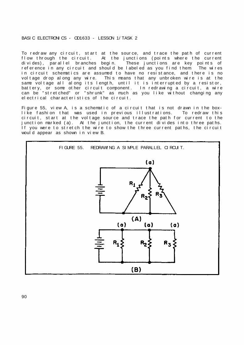
BASIC ELECTRONICS - OD1633 - LESSON 1/TASK 2
To redraw any circuit, start at the source, and trace the path of currentflow through the circuit. At the junctions (points where the currentdivides), parallel branches begin. These junctions are key points ofreference in any circuit and should be labeled as you find them. The wiresin circuit schematics are assumed to have no resistance, and there is novoltage drop along any wire. This means that any unbroken wire is at thesame voltage all along its length, until it is interrupted by a resistor,battery, or some other circuit component. In redrawing a circuit, a wirecan be "stretched" or "shrunk" as much as you like without changing anyelectrical characteristics of the circuit.
Figure 55, view A, is a schematic of a circuit that is not drawn in the box-like fashion that was used in previous illustrations. To redraw thiscircuit, start at the voltage source and trace the path for current to thejunction marked (a). At the junction, the current divides into three paths.If you were to stretch the wire to show the three current paths, the circuitwould appear as shown in view B.
FIGURE 55. REDRAWING A SIMPLE PARALLEL CIRCUIT.
90
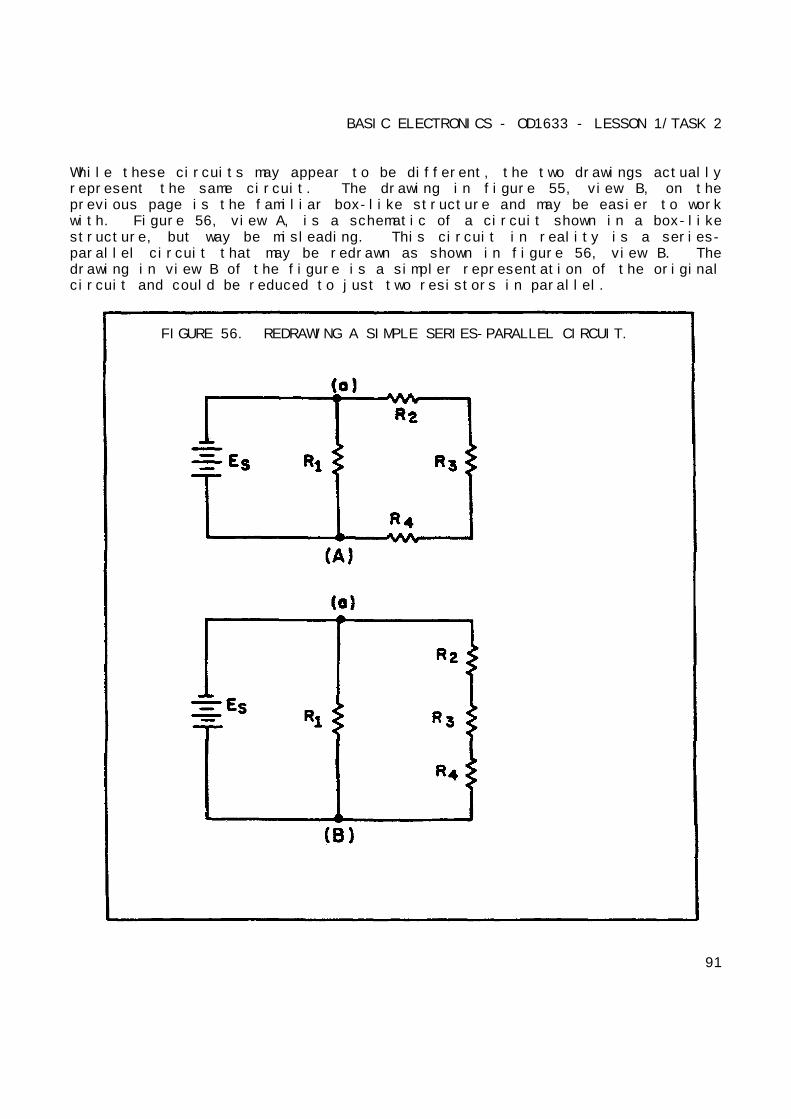
BASIC ELECTRONICS - OD1633 - LESSON 1/TASK 2
While these circuits may appear to be different, the two drawings actuallyrepresent the same circuit. The drawing in figure 55, view B, on theprevious page is the familiar box-like structure and may be easier to workwith. Figure 56, view A, is a schematic of a circuit shown in a box-likestructure, but way be misleading. This circuit in reality is a series-parallel circuit that may be redrawn as shown in figure 56, view B. Thedrawing in view B of the figure is a simpler representation of the originalcircuit and could be reduced to just two resistors in parallel.
FIGURE 56. REDRAWING A SIMPLE SERIES-PARALLEL CIRCUIT.
91
BASIC ELECTRONICS - OD1633 - LESSON 1/TASK 2
c. Redrawing a Complex Circuit. Figure 57, view A, on the followingpage, shows a complex circuit that may be redrawn for clarification in thefollowing steps.
NOTE
As you redraw the circuit, draw it in simple box-likeform. Each time you reach a junction, a new branch iscreated by stretching or shrinking wires.
Step 1: Start at the negative terminal of the voltage source. Current flowsthrough R1, to a junction and divides into three paths; label this junction
(a). Follow one of the paths of current through R2 and R3 to a junction
where the current divides into two more paths. This junction is labeled(b).
The current through one branch of this junction goes through R5 and back to
the source--the most direct path. Now that you have completed a path forcurrent to the source, return to the last junction, (b). Follow the currentthrough the other branch from this junction. Current flows from junction(b) through R4 to the source. All the paths from junction (b) has been
traced. Only one path from junction (a) has been completed. You must nowreturn to junction (a) to complete the other two paths. From junction (a)the current flows through R7 hack to the source. There are no additional
branches on this path. Return to junction (a) to trace the third path fromthis junction. Current flows through R6 and R8 and comes to a junction.
Label this junction (c). From junction (c) one path for current is throughR9 to the source. The other path for current from junction (c) is through
R10 to the source. All the junctions in this circuit have now been labeled.
The circuit and junction can be redrawn as shown in figure 57 (view C). Itis much easier to recognize the series and parallel paths in the redrawncircuit.
d. Effects of Open and Short Circuits. Earlier in this topic, theterms open and short circuits were discussed. The following discussiondeals with the effects on a circuit when an open or a short occurs.
92
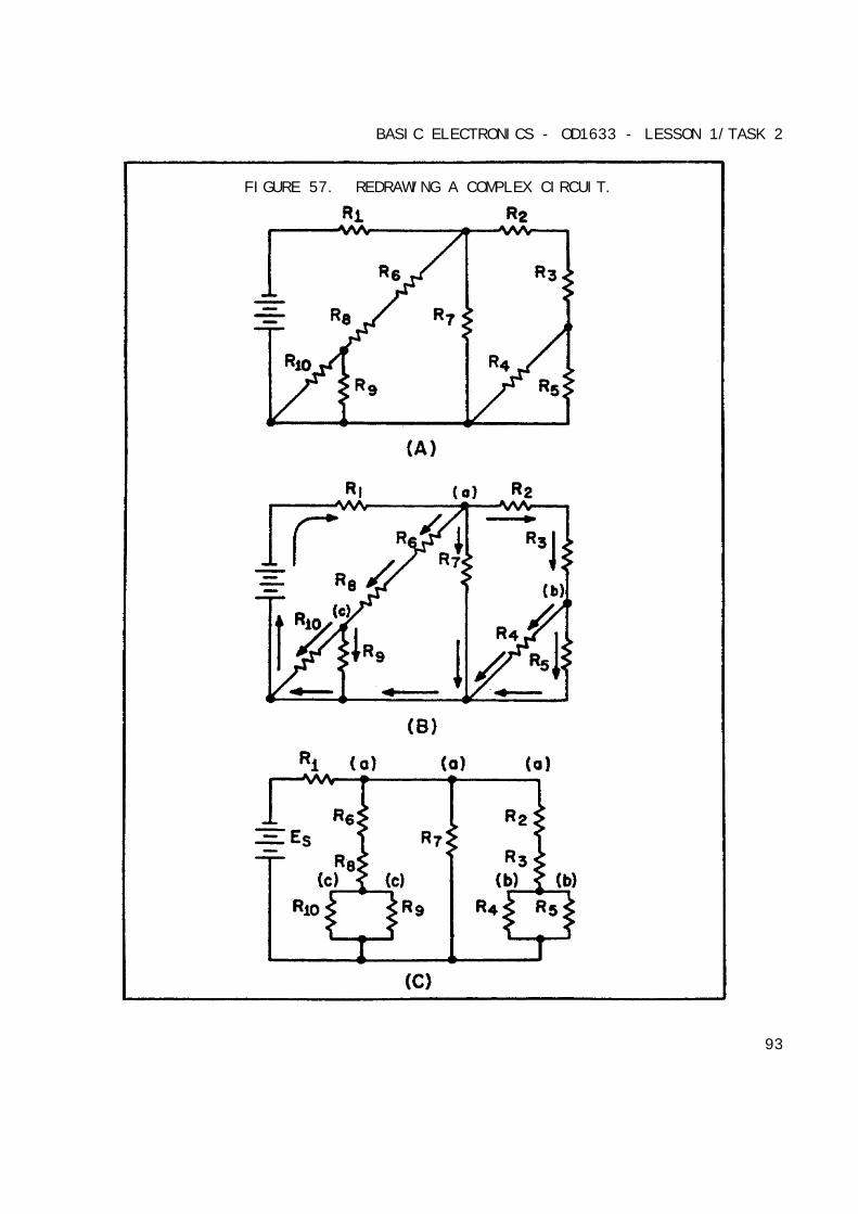
BASIC ELECTRONICS - OD1633 - LESSON 1/TASK 2
FIGURE 57. REDRAWING A COMPLEX CIRCUIT.
93

BASIC ELECTRONICS - OD1633 - LESSON 1/TASK 2
The major difference between an open in a parallel circuit and an open in aseries circuit is that in the parallel circuit the open would notnecessarily disable the circuit. If the open condition occurs in a seriesportion of the circuit, there will be no current because theme is nocomplete path for current flow. If, on the other hand, the open occurs in aparallel path, some current will flow in the circuit. The parallel branchwhere the open occurs will be effectively disabled, total resistance of thecircuit will increase, and total current will decrease.
To clarify these points, figure 58 on the following page illustrates aseries-parallel circuit. First, the effect of an open in a series portionof this circuit will be examined. View A shows the normal circuit RT = 40
Ohms and IT = 3 amps. In view B, an open is shown in the series portion of
the circuit. There is no complete path for current, and the resistance ofthe circuit is considered to be infinite.
In view C, an open is shown in the parallel branch of R3. There is no path
for current through R3. In the circuit, current flows through R1 and R2only. Since there is only one path for current flow, R1 and R2 are
effectively in series.
Under these conditions, RT = 120 Ohms and IT = 1 amp. As you can see, when
an open occurs in a parallel branch, total circuit resistance increases andtotal circuit current decreases.
A short circuit in a parallel network has an effect similar to short in aseries circuit. In general, the short will cause an increase in current andthe possibility of component damage, regardless of the type of circuitinvolved. To illustrate this point, figure 59 on page 96 shows a series-parallel network in which shorts are developed. In view A, the normalcircuit is shown (RT = 40 Ohms and IT = 3 amps).
In view B, R1 has shorted. R1 now has zero Ohms of resistance. The total
of the resistance in the circuit is now equal to the resistance of theparallel network of R2 and R3, or 20 Ohms. Circuit current has increased to
6 amps. All of this current goes through the parallel network (R2, R3), and
this increase in current would most likely damage the components.
94
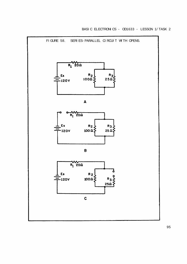
BASIC ELECTRONICS - OD1633 - LESSON 1/TASK 2
FIGURE 58. SERIES-PARALLEL CIRCUIT WITH OPENS.
95
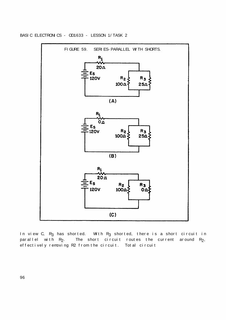
BASIC ELECTRONICS - OD1633 - LESSON 1/TASK 2
FIGURE 59. SERIES-PARALLEL WITH SHORTS.
In view C, R3 has shorted. With R3 shorted, there is a short circuit in
parallel with R2. The short circuit routes the current around R2,
effectively removing R2 from the circuit. Total circuit
96
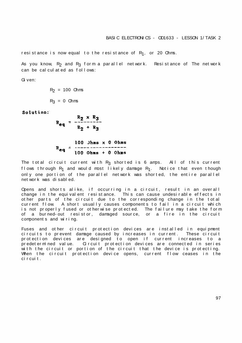
BASIC ELECTRONICS - OD1633 - LESSON 1/TASK 2
resistance is now equal to the resistance of R1, or 20 Ohms.
As you know, R2 and R3 form a parallel network. Resistance of The network
can be calculated as follows:
Given:
R2 = 100 Ohms
R3 = 0 Ohms
The total circuit current with R3 shorted is 6 amps. All of this current
flows through R1 and would most likely damage R1. Notice that even though
only one portion of the parallel network was shorted, the entire parallelnetwork was disabled.
Opens and shorts alike, if occurring in a circuit, result in an overallchange in the equivalent resistance. This can cause undesirable effects inother parts of the circuit due to the corresponding change in the totalcurrent flow. A short usually causes components to fail in a circuit whichis not properly fused or otherwise protected. The failure may take the formof a burned-out resistor, damaged source, or a fire in the circuitcomponents and wiring.
Fuses and other circuit protection devices are installed in equipmentcircuits to prevent damage caused by increases in current. These circuitprotection devices are designed to open if current increases to apredetermined value. Circuit protection devices are connected in serieswith the circuit or portion of the circuit that the device is protecting.When the circuit protection device opens, current flow ceases in thecircuit.
97
BASIC ELECTRONICS - OD1633 - LESSON 1/TASK 2
7. Batteries
A battery is a voltage source that uses chemical action to produce avoltage. In many cases the term battery is applied to a single cell, suchas the flashlight battery. In the case of a flashlight that uses a batteryof 1.5 volts, the battery is a single cell. The flashlight that is operatedby 6 volts uses 4 cells in a single case, and this is a battery composed ofmore than one cell. There are three ways to combine cells to form abattery.
a. Capacity and Rating of Batteries. The capacity of a battery ismeasured in ampere-hours. The ampere-hour capacity is equal to the productof the current in amperes and the time in hours during which the batterywill supply this current. The ampere-hour capacity varies inversely withthe discharge current. For example, a 400 ampere-hour battery will deliver400 amperes for 1 hour or 100 amperes for 4 hours.
Storage batteries are rated according to the rate of discharge and ampere-hour capacity. Most batteries are rated according to a 20-hour rate ofdischarge. That is, if a fully charged battery is completely dischargedduring a 20-hour period, it is discharged at the 20-hour rate. Thus, if abattery can deliver 20 amperes continuously for 20 hours, the battery has arating of 20 amperes x 20 hours or 400 ampere-hours. Therefore, the 20-hourrating is equal to the average current that a battery is capable ofsupplying without interruption for an interval of 20 hours.
NOTE
Aircraft batteries are rated according to a one-hourrate of discharge.
All standard batteries deliver 100 percent of their available capacity ifdischarged in 20 hours or more, but they will deliver less than theiravailable capacity if discharged at a faster rate. The faster theydischarge, the less ampere-hour capacity they have.
98
BASIC ELECTRONICS - OD1633 - LESSON 1/TASK 2
The low-voltage limit, as specified by the manufacturer, is the limit beyondwhich very little useful energy can be obtained from a battery. This low-voltage limit is normally a test used in battery shops to determine thecondition of a battery.
b. Combining Cells. In many cases, a battery-powered device mayrequire more electrical energy than one cell can provide. The device mayrequire either a higher voltage or more current, and in some cases both.Under such conditions, it is necessary to combine or interconnect asufficient number of cells to meet the higher requirements. Cells connectedin series provide a higher voltage, while cells connected in parallelprovide a higher current capacity. To provide adequate power when bothvoltage and current requirements are greater than the capacity of one cell,a combination series-parallel network of cells must be used.
(1) Series-Connected Cells. Assume that a load requires power supplyof 6 volts and a current capacity of 1/8 ampere. Since a single cellnormally supplies a voltage of only 1.5 volts, more than one cell is needed.To obtain a higher voltage, the cells are connected in series as shown infigure 60 on the following page.
View B in figure 60 is schematic representation of the circuit shown in viewA. The load is shown by the resistance symbol and the battery is indicatedby one long and one short line per cell.
In a series hookup, the negative electrode (cathode) of the first cell isconnected to the positive electrode (anode) of the second cell, the negativeelectrode of the positive of the third, etc. The positive electrode of thefirst cell and the negative electrode of the last cell then serve as theterminals of the battery. In this way, the voltage is 1.5 volts for eachcell in the series line. There are four cells, so the output terminalvoltage is 1.5 x 4, or 6 volts. When connected to the load, 1/8 ampereflows through the load and each cell of the battery. This is within thecapacity of each cell. Therefore, only four series-connected cells areneeded to supply this particular load.
99
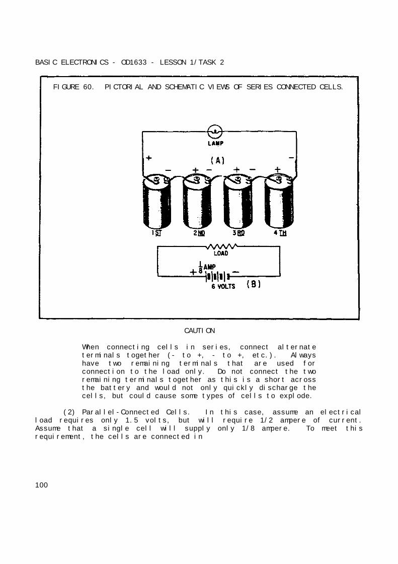
BASIC ELECTRONICS - OD1633 - LESSON 1/TASK 2
FIGURE 60. PICTORIAL AND SCHEMATIC VIEWS OF SERIES CONNECTED CELLS.
CAUTION
When connecting cells in series, connect alternateterminals together (- to +, - to +, etc.). Alwayshave two remaining terminals that are used forconnection to the load only. Do not connect the tworemaining terminals together as this is a short acrossthe battery and would not only quickly discharge thecells, but could cause some types of cells to explode.
(2) Parallel-Connected Cells. In this case, assume an electricalload requires only 1.5 volts, but will require 1/2 ampere of current.Assume that a single cell will supply only 1/8 ampere. To meet thisrequirement, the cells are connected in
100

BASIC ELECTRONICS - OD1633 - LESSON 1/TASK 2
parallel as shown in figure 61, view A, and schematically represented inview B. In a parallel connection, all positive cell electrodes areconnected to one line, and all negative electrodes are connected to theother. No more than one cell is connected between the lines at any onepoint; so the voltage between the lines is the same as that of one cell, or1.5 volts. However, each cell may contribute its maximum allowable currentof 1/8 amperes to the line. There are four cells, so the total current is1/8 x 4 = 1/2 ampere. In this case, four cells in parallel have enoughcapacity to supply a load requiring 1/2 ampere at 1.5 volts.
FIGURE 61. PICTORIAL AND SCHEMATIC VIEWS OF PARALLEL-CONNECTED CELLS.
(3) Series-Parallel-Connected Cells. Figure 62 on the following pagedepicts a battery network supplying power to a load requiring both a voltageand current greater than one cell can provide. To provide the required 4.5volts, groups of three 1.5 volt cells are connected in series. To providethe
101
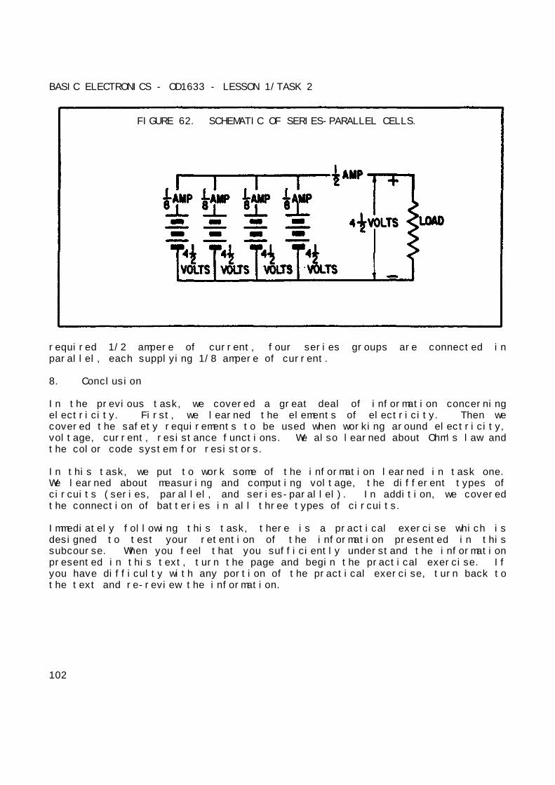
BASIC ELECTRONICS - OD1633 - LESSON 1/TASK 2
FIGURE 62. SCHEMATIC OF SERIES-PARALLEL CELLS.
required 1/2 ampere of current, four series groups are connected inparallel, each supplying 1/8 ampere of current.
8. Conclusion
In the previous task, we covered a great deal of information concerningelectricity. First, we learned the elements of electricity. Then wecovered the safety requirements to be used when working around electricity,voltage, current, resistance functions. We also learned about Ohm's law andthe color code system for resistors.
In this task, we put to work some of the information learned in task one.We learned about measuring and computing voltage, the different types ofcircuits (series, parallel, and series-parallel). In addition, we coveredthe connection of batteries in all three types of circuits.
Immediately following this task, there is a practical exercise which isdesigned to test your retention of the information presented in thissubcourse. When you feel that you sufficiently understand the informationpresented in this text, turn the page and begin the practical exercise. Ifyou have difficulty with any portion of the practical exercise, turn back tothe text and re-review the information.
102
BASIC ELECTRONICS - OD1633 - LESSON 1/PE 1
PRACTICAL EXERCISE 1
1. Instructions
Read the scenario and respond to the requirements that follow the scenario.
2. Scenario
You have been assigned to the military advisory group (MAG) located atRiyadh, Saudi Arabia. While stationed at Riyadh, you have workedextensively with the Saudi Arabian Army Ordnance Corps (SAAOC).
You have been tasked with assisting SSG Abdul Ibn Saud with developing acourse in basic electronics to be taught to Fire Control InstrumentRepairmen at the Saudi Arabian Army Ordnance School (SAAOS), Taif. OnMonday morning you fly to Taif and meet with SSG Abdul. The two of you havedecided that the best course of action is for each of you to develop alesson plan and test questions. You then will sit down and combine bothlesson plans and test questions to make one.
You fly back to Riyadh and begin developing your lesson plan. You haveworked all week and through the weekend developing the lesson plan.Tomorrow is Monday and you are scheduled to meet with SSG Abdul. All thatremains is to prepare an answer sheet for the test items.
3. Requirement
Using your knowledge of electricity and electronics, and this subcourse,provide an answer sheet for the following questions.
a. State the difference between conductors and insulators.
b. What two agents should be used to extinguish an electrical fire?
c. Define ampere, voltage, and resistance.
d. What is meant by the term efficiency of an electrical device?
e. Define a series circuit.
103
BASIC ELECTRONICS - OD1633 - LESSON 1/PE 1
f. Define an open circuit.
g. Define a short circuit.
h. Define a parallel circuit.
104
BASIC ELECTRONICS - OD1633 - LESSON 1/PE 1
LESSON 1. PRACTICAL EXERCISE - ANSWERS
Requirement
a. A conductor is defined as any material that will permit the flow ofelectricity through it, while an insulator is defined as any materialthat blocks the flow of electricity through the material.
b. The two types of agents used to extinguish a fire are carbon dioxide(CO2) and potassium chloride or purple K (PKP).
c. Ampere is defined as the basic unit of electrical current. Voltage isthe term used to signify electrical pressure. Voltage is a forcewhich causes current to flow through an electrical conductor.Resistance is defined as the opposition which a device or materialoffers to the flow of current.
d. The term efficiency of an electrical device is the ratio of powerconverted to useful energy divided by the power consumed by thedevice.
e. A series circuit is defined as a circuit that contains only one pathfor current flow.
f. A circuit is said to be an open circuit when a break exists in acomplete conducting pathway.
g. A short circuit is an accidental path of low resistance which passesan abnormally high amount of current.
h. A parallel circuit is defined as a circuit having more than onecurrent path connected to a common voltage source.
105
BASIC ELECTRONICS - OD1633 - REFERENCE
REFERENCES
106
BASIC ELECTRONICS - OD1633 - REFERENCE
REFERENCES
The following documents were used as resource materials in developing thissubcourse:
FM 11-60
107