Embed Size (px)
Citation preview

1
Layered Fabrication of Branched Networks using Lindenmayer Systems
O. Yasar, M. Martin, C. Harris, S. Sun, B. Starly School of Industrial Engineering
University of Oklahoma, Norman, OK 73019 Abstract A current challenge impeding the growth of bone tissue engineering is the lack of functional scaffolds of geometric sizes greater than 10mm due to the inability of cells to survive deep within the scaffold. It is hypothesized that these scaffolds must have an inbuilt nutrient distribution network to sustain the uniform growth of cells. In this paper, we seek to enhance the design and layered fabrication of scaffold internal architecture through the development of Lindenmayer systems, a graphical language based theory to create nutrient delivery networks. The scaffolds are fabricated using the Texas Instruments DLP™ system through UV‐photopolymerization to produce polyethylene glycol hydrogels with internal branch structures. The paper will discuss the Lindenmayer system, process planning algorithms, layered fabrication of samples, challenges and future tasks Keywords: UV Mask‐less Photolithography, Hydrogel Patterning, Lindenmayer Systems, DLP Systems
1. INTRODUCTION Scaffold guided tissue engineering necessitates the need for biologically inspired artificial matrices to recreate the natural three dimensional microenvironment for conducive cell and tissue growth. These scaffolds provide the framework upon which cells can attach, migrate, proliferate and differentiate into the desired tissue. A measure of success within this multidisciplinary technological field is how well cells are able to survive and organize themselves to form the desired tissue intended for a specific application. Such organizational processes are largely influenced by cell interaction with the surrounding material, surface topography, scaffold interior architecture [1‐3] and nutritional network that feed the cells. The tissue scaffold micro‐architecture is believed to influence the behavior of cells and the biological function of tissues by providing a nutritional pathway as well as a spatial distribution for cell growth and proliferation [4]. Several studies have indicated that cells can be coaxed to migrate and grow along the direction of designed micro‐channels/struts, through which the required cell spatial distribution and tissue function can be realized [5‐8]. In certain applications, certain kinds of cells such as chondrocytes need to be restricted within void spaces [9], and therefore the architecture must support such design requirements.
552

2
In vertebrate animals, circulatory systems distribute essential nutrients and carry waste products to and from cells. They are composed of arteries, capillaries and veins on the order of one to tens of microns in dimension that form a closed system. Any engineered scaffold or matrix must have a nutrient distribution system that is essential to the success of tissue engineered products particularly for bone, liver, kidney. Very limited work has been reported on the fabrication of a vasculature system within scaffolds or hydrogel matrices resulting in successful scaffolds that have limited thickness (less than 5mm). Larger and thicker scaffolds (5mm or larger) to treat critical size defects have been reported with limited success primarily due to the inability of cells to survive deep within the scaffold [10]. It has been hypothesized that thick scaffolds must have an inbuilt nutrient distribution network to allow for the uniform growth of cells within their matrices. This would allow sufficient time before the cells themselves can recreate their own capillary network (a process known as angiogenesis). Some of challenges faced by the scaffold and hydrogel fabrication research community on the creation of such a branched system are listed below: a) Inability of current fabrication processes (either RP or chemical methods) to create
an interconnected micro capillary network within the scaffold which would help to sustain the cells during the initial phase.
b) Chemical based methods of fabrication lack the capability of producing a well controlled interconnected network of channels within a scaffold or hydrogel. On the other hand, the growing acceptance of Solid freeform fabrication systems for the fabrication of scaffolds requires the input of a CAD model. The design of an intricate network of channels within a CAD model is memory intensive and cumbersome using existing commercially available CAD systems.
c) Even if a well distributed network of channels (such as scaffolds produced using FDM, PED) with a 0˚/90˚ pattern is obtained, the pores are gradually filled up with the growth of cells, preventing the flow of nutrients deep into the scaffold. Hence, there does not seem to be an effective way of keeping the channels open for continuous delivery of nutrients.
These challenges prompt the need to develop new design methodologies that address the use of creating nutrient delivery networks and guided struts within scaffolds without placing a memory overload on either graphic hardware or data transfer capabilities. In this paper, our objective is to develop new internal pore architecture designs by making use of rewriting systems. The use of the recursive rewriting rules dramatically expands the pore architecture design space fabricated by such systems. The paper is organized as follows: The second section of this paper explain the basics of Lindenmayer systems, followed by sections on how such systems can be used to create interesting patterns without the overwhelming need for powerful CAD hardware/software systems. The third section details a relatively new SFF technique based on the maskless photopolymerization of patterned hydrogels using the Texas Instruments DLP™ based system. We describe the fabrication of the L‐system structures using Polyetheylene
553

3
Glycol diacrylates (PEGDA) as the model biopolymer. In the last section, the paper concludes by a brief discussion on the results and future research prospects. 2. LINDENMAYER SYSTEMS Lindenmayer systems (L‐systems) were developed by a Hungarian theoretical botanist Aristid Lindenmayer in 1968 and most commonly used in the graphical modeling of growth and development of plants, bacteria and algae. It essentially consists of a set of axioms and rules used to generate recursive systems. The first L‐system was used to model the growth of algae and is represented in Figure 1(a) [11]. The axiom is stated to be “AB” and the rules are set to be such that in successive rewriting steps, all A’s are replaced by ‘AB’ and all B’s are replaced by ‘A’. Repeating the rewriting process iteratively for a finite number of steps, we generate a sequence of strings that are replaced simultaneously at each step of the process. Due to this parallel rewriting mechanism, L‐systems have the capability to model biological phenomena such as cellular growth by simulating cell division and death.
Axiom: F‐F‐F‐F Rules: F F+F‐F+F
Fig 1(a): Rewriting Process Fig 1(b): Turtle Representation
Fig 1(c): 2D Pattern created using the rules presented in (b).
These L‐systems can be extended to geometric interpretation using Turtle graphics, to generate fractal curves, space filling curves and plant like structures [11]. The notation of turtle graphics can be interpreted as follows. The state of the turtle is given by its geometric Cartesian coordinates (x,y) and the orientation of the turtle (θ). The turtle can be instructed to move forward (F) and instructed to draw a line by a specified step distance (d), move forward without drawing a line (f), rotate counterclockwise (+) or clockwise (‐) by a defined angle (δ). For example, consider the set of axiom and rules in Figure 1 (b). The axiom F‐F‐F‐F at n=1 defines a rectangle. If all F’s are replaced by F+F‐F+F with δ=90˚ and repeated n=4 times, we obtain the pattern shown in Figure 1(c). The turtle representation can also be extended into the third dimension as shown in Figure 2. The axiom F is recursively rewritten n=3 times by the rule F&F‐F&F, where ‘&’ stands for pitch down by angle δ=90˚. Other symbols such as ‘^’and ‘\’ exist for the remaining axes of rotation. Complex geometric patterns both in 2D and 3D can be obtained using the recursive nature of L‐systems. Extensions of the system representation include color code inclusions, geometric surface patch association, leaf‐apex‐branch notation etc. The authors refer readers to the excellent free online book resource by Prusinkiewicz that
554
4
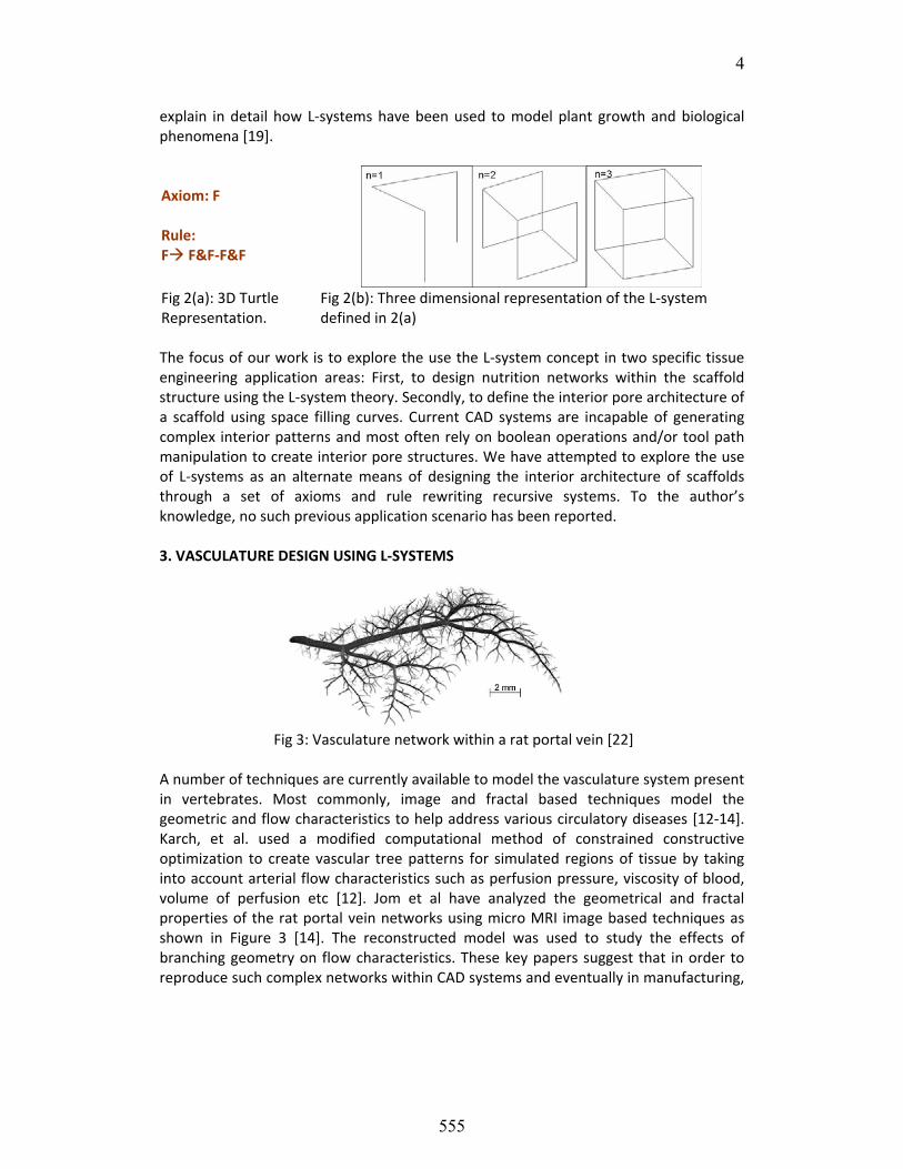
explain in detail how L‐systems have been used to model plant growth and biological phenomena [19]. Axiom: F Rule: F F&F‐F&F
Fig 2(a): 3D Turtle Representation.
Fig 2(b): Three dimensional representation of the L‐system defined in 2(a)
The focus of our work is to explore the use the L‐system concept in two specific tissue engineering application areas: First, to design nutrition networks within the scaffold structure using the L‐system theory. Secondly, to define the interior pore architecture of a scaffold using space filling curves. Current CAD systems are incapable of generating complex interior patterns and most often rely on boolean operations and/or tool path manipulation to create interior pore structures. We have attempted to explore the use of L‐systems as an alternate means of designing the interior architecture of scaffolds through a set of axioms and rule rewriting recursive systems. To the author’s knowledge, no such previous application scenario has been reported. 3. VASCULATURE DESIGN USING L‐SYSTEMS
Fig 3: Vasculature network within a rat portal vein [22] A number of techniques are currently available to model the vasculature system present in vertebrates. Most commonly, image and fractal based techniques model the geometric and flow characteristics to help address various circulatory diseases [12‐14]. Karch, et al. used a modified computational method of constrained constructive optimization to create vascular tree patterns for simulated regions of tissue by taking into account arterial flow characteristics such as perfusion pressure, viscosity of blood, volume of perfusion etc [12]. Jom et al have analyzed the geometrical and fractal properties of the rat portal vein networks using micro MRI image based techniques as shown in Figure 3 [14]. The reconstructed model was used to study the effects of branching geometry on flow characteristics. These key papers suggest that in order to reproduce such complex networks within CAD systems and eventually in manufacturing,
555

5
additional work is required that follows a Design for manufacturing (DFM) approach. To enable this, there is a need for design algorithms to include manufacturing constraints while developing the artificial nutrient delivery network tree. The use of L‐system is particularly attractive for vascular network design scenario for the following reasons: 1) The axiom and rule based rewriting scheme presents a simple yet powerful method to create fractal based networks. 2) Ease of inclusion of parameters and constraints within the rewriting system to meet specific design criteria through the use of conditional constraints. 3) Ability to associate ‘features’ or geometric entities within the rewriting system. 4) Ease of extensibility since L‐systems were originally developed for plant modeling where branches, roots and nodes are common design features. The following sub‐sections describe how L‐systems can be used in the creation of vascular patterns with sample scaffold shapes. For illustrative purposes, we have hypothesized a square shaped scaffold. The figures were created using a trial L‐system software [15]. The generated vascular patterns are examples of circulation networks that can be used within cell encapsulated hydrogel scaffolds. 3.1 Layered Patterning of Branching networks Layered Manufacturing (LM) systems obtain layer by layer contour information from CAD models. Therefore, it is conceivable that 2D vasculature patterns can be laid out on specific layers and then transferred to the LM systems for fabrication. To create branch patterns, parametric L‐systems can be used of the form shown in Figure 4(a). Successive generation of patterns yield branches of reduced length set forth by the parameter ‘s/R’ as shown in Figures 4(b‐c). The amount of branching steps will depend on several factors namely, resolution of LM system, perfusion necessity, material characteristics etc. Each of the patterns can be arranged within specific layers of the scaffold as needed and processed to obtain the necessary tool path instruction set as depicted in Figure 5.
Fig 4(a): Parametric L‐system Fig 4(b): Branching pattern at n=5
Fig 4(c): Branching pattern at n=10
556

6
Fig 5: Final assembly of branching patterns on specific layers within the scaffold.
3.2 3D Branched network Branched patterns to form a three dimensional network can be formed within the interior of the scaffold through parametric L‐system representation that branches out in three dimensions. An example of a branched network rewriting system is shown below in Figure 6 and graphically displayed in Figure 7. The length of the sub‐branches is controlled by the factor ‘R’. The symbols ‘\’ and ‘&’ instruct the system to branch out in adjacent planes. The model can be further sliced to obtain the layer information and processed to instruct the specific RP system used. It should be noted that not all RP systems will be capable to generate a branched network. A nutritional flow channel network of the nature shown in Figure 8, known as the 3D Hilbert path is constructed and can be incorporated into a hydrogel scaffold. If cells are encapsulated in the scaffold, medium flowing through the channels can diffuse into the surrounding structure and thereby maintain cellular needs. It is therefore seen that complex pathways can be generated by recursive rewriting systems that do not require expensive computing systems.
Fig 6: 3D Branching L‐System
Fig 7(a): N=1 branch Fig 7(b): N=2 Branches Fig 7(c): N=4 branched network
557

7
4. FABRICATION USING DLP™ BASED MASKLESS PHOTOPOLYMERIZATION Recent advancement in manufacturing methods such as patterning and deposition technologies have enabled researchers to spatially control hydrogel architectural features through the use of soft lithography [16‐18], photolithography [19‐20] and solid freeform fabrication [21‐24]. These techniques have produced patterned hydrogels with desired chemical and mechanical properties capable of designing biomimetic microenvironments. Soft lithographic techniques have produced feature sizes in ranges of 20μm and above but have limited 3D capability. Solid Freeform fabrication technologies enable the production of complex 3D hydrogels due to its CAD integration but are generally limited to a minimum of 100μm feature resolutions. Photolithographic methods have produced hydrogels by the direct exposure of the polymer solution to UV radiation to produce micro‐patterned scaffolds with feature sizes in the range of 50μm or more. Until recently, the photolithographic technique had limited capability in producing three dimensional scaffolds due to the lack of true three dimensional formation capabilities. With the development of the maskless projection photolithographic and micro‐stereolithography, it is now possible to create complex three‐dimensional scaffolds with defined architecture and minimum feature sizes on the order of 50μm [25,26]. The maskless projection photolithography has the capability of producing hydrogels with well defined, repeatable and complex 3D features due to its integration with CAD systems. This automated technique can be extended to potentially create multi‐material heterogeneous cell constructs. An experimental setup was designed for photo‐patterning of the PEGDA hydrogels as shown in the Figure 8. The main components of the setup include a UV light source (Cure Spot™ 50), UV Fused Silica Planoconvex collimating lenses (f=50mm, Newport, CA), 365nm filter (Edmund optics, NJ), Texas Instruments DMD, projection lens (f=25mm, Newport, CA) and a mold to contain the pre‐polymer solution. The function and working of the DMD have been detailed in Sun et al and Liu et al and the readers are referred to those papers for further information on the setup and functioning [25,27].
Fig 8: Schematic of the maskless DLP™ photolithography process.
558
8
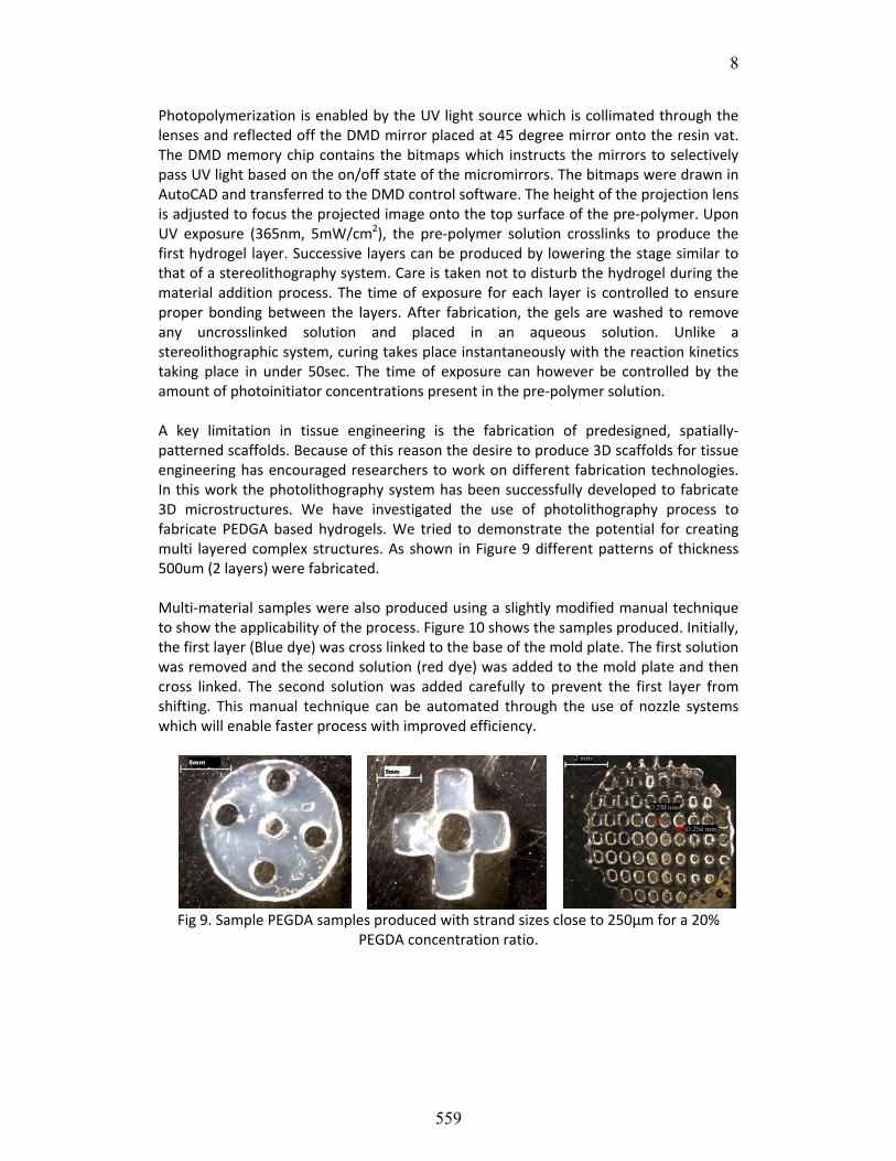
Photopolymerization is enabled by the UV light source which is collimated through the lenses and reflected off the DMD mirror placed at 45 degree mirror onto the resin vat. The DMD memory chip contains the bitmaps which instructs the mirrors to selectively pass UV light based on the on/off state of the micromirrors. The bitmaps were drawn in AutoCAD and transferred to the DMD control software. The height of the projection lens is adjusted to focus the projected image onto the top surface of the pre‐polymer. Upon UV exposure (365nm, 5mW/cm2), the pre‐polymer solution crosslinks to produce the first hydrogel layer. Successive layers can be produced by lowering the stage similar to that of a stereolithography system. Care is taken not to disturb the hydrogel during the material addition process. The time of exposure for each layer is controlled to ensure proper bonding between the layers. After fabrication, the gels are washed to remove any uncrosslinked solution and placed in an aqueous solution. Unlike a stereolithographic system, curing takes place instantaneously with the reaction kinetics taking place in under 50sec. The time of exposure can however be controlled by the amount of photoinitiator concentrations present in the pre‐polymer solution. A key limitation in tissue engineering is the fabrication of predesigned, spatially‐patterned scaffolds. Because of this reason the desire to produce 3D scaffolds for tissue engineering has encouraged researchers to work on different fabrication technologies. In this work the photolithography system has been successfully developed to fabricate 3D microstructures. We have investigated the use of photolithography process to fabricate PEDGA based hydrogels. We tried to demonstrate the potential for creating multi layered complex structures. As shown in Figure 9 different patterns of thickness 500um (2 layers) were fabricated. Multi‐material samples were also produced using a slightly modified manual technique to show the applicability of the process. Figure 10 shows the samples produced. Initially, the first layer (Blue dye) was cross linked to the base of the mold plate. The first solution was removed and the second solution (red dye) was added to the mold plate and then cross linked. The second solution was added carefully to prevent the first layer from shifting. This manual technique can be automated through the use of nozzle systems which will enable faster process with improved efficiency.
Fig 9. Sample PEGDA samples produced with strand sizes close to 250µm for a 20%
PEGDA concentration ratio.
559

9
Fig 10: Multi Material scaffolds. Two different dyed solutions were cross linked to produce the desired branched structure. For clarity purposes, images with 3 layers are not shown. (Scale bar: 5mm, strands at 160‐180µm) 5. DISCUSSION Based on the preliminary results shown in sections 3.1 and 3.2, the L‐systems used to generate the branched networks were selected with no prior definition of design criteria. The selected parameters are arbitrary and are shown primarily to prove the applicability of using the formulation of the L‐system theory to the generation of complex vascular patterns. The benefits of using the L‐system theory are: a) Use of recursive systems to generate complex patterns without the excessive use of CAD graphic resources. The pattern trajectories can be generated in real time and can be implicitly associated with the outer architecture of the scaffold structure prior to manufacturing process plan generation. b) Although not described in this paper, the L‐system formulation can be modified to incorporate engineering design constraints into the axiom and rule definition through the use of conditional statements. c) The L‐system can be parameterized to generate branched networks for specific application depending on nutrition delivery needs. Thus a single L‐system definition can be used to generate several topological networks while maintaining geometry. d) STL files need not be generated and can be directly converted to process tool path instructions for fabrication, thus avoiding the bottlenecks of having to convert multi‐scale models to the triangulated format. e) The L‐systems can be used to incorporate multiple material definitions within the formulation, hence providing the capability to generate heterogeneous models. The fabrication process although preliminary at this stage, shows promising results to the capability of producing scaffolds with complex interior architecture and feature resolution at about 100µm and larger. The swelling effects of the PEGDA prevents the fabrication of highly repeatable samples below 100µm. This effect can be negated by the addition of other polymer blends into PEGDA such as Poly Lactic Acid (PLA) to increase the mechanical strength and biocompatibility of the polymer matrix.
560

10
6. CONCLUSIONS AND SUMMARY Modeling, design and fabrication of tissue scaffolds to meet multiple biological and biophysical requirements is always a challenge in tissue engineering. This is further amplified when designing load bearing scaffolds for bone and cartilage tissue application. In these cases, tissue scaffolds need to be designed with intricate architecture, porosity, pore size and shape, and interconnectivity in order to provide the needed structural strength, transport nutrients, and the micro‐environment for cell and tissue in‐growth. By selecting the appropriate unit cell interior structures, properties such as the effective mechanical properties, diffusion and permeability characteristics can be controlled. Depending on the fabrication method used, varying complex internal patterns can be fabricated. In this paper, we have presented the use of Lindenmayer systems in designing vasculature networks that could potentially be incorporated in hydrogel scaffolds. The use of a recursive based rewriting system provides a powerful method to create complex architecture patterns within the interior of scaffolds. Future research efforts will be undertaken to explore the development of L‐system axioms and rules that incorporate feature and manufacturing constraints. The goal would be to design scaffold interior architecture designs which take into account manufacturing process constraints and design specifications. It is hoped that by providing complex internal patterns that mimic the cellular structure, cells can be guided to form the intended structure. On the manufacturing front, the system will need to be automated to provide a fully integrated SFF system capable of repeatable and stable fabrication process through accurate modeling and control of the various fabrication parameters. 6. ACKNOWLEDGEMENTS The research results discussed in this publication were made possible by the OHRS award #HR07‐158 from the Oklahoma Center for Advancement of Science and Technology (OCAST) and the Office of Vice President for Research at the University of Oklahoma. 7. REFERENCES [1] Griffith LG.: Emerging design principles in biomaterials and scaffolds for tissue
engineering, Ann N Y Acad Sci., 961: 2002, 83‐95. [2] Tran KT; Griffith L; Wells A.: Extracellular matrix signaling through growth factor
receptors during wound healing, Wound Repair Regen., 12(3), 2004, 262‐8. [3] Pirone DM; Chen C S.: Strategies for engineering the adhesive microenvironment,
Mammary Gland Biol Neoplasia., 9(4), 2004, 405‐17. [4] Langer R.; Vacanti, J. P.: Tissue Engineering, Science, 260, 1993, 920‐926. [5] Prasad C K; Krishnan L K.: Effect of passage number and matrix characteristics on
differentiation of endothelial cells cultured for tissue engineering, Biomaterials, 26(28), 2005, 5658‐67
[6] Hutmacher DW; Schantz T; Zein I; Ng KW; Teoh SH; Tan KC: Mechanical properties and cell cultural response of polycaprolactone scaffolds designed and fabricated
561

11
via fused deposition modeling, Journal of Biomedical Materials Research, 55, 2001, 203‐216.
[7] Christopher S. C; Mrksich M.; Huang S.; Whitesides G.M.; Ingber D: Geometric Control of Cell Life and Death, Science, 276, 1997, 1425‐28
[8] Li Y; Ma T; Kniss DA; Lasky LC; Yang ST: Effects of filtration seeding on cell density, spatial distribution, and proliferation in nonwoven fibrous matrices, Biotechnol Prog, 17(5): 2001, 935‐44.
[9] Taguchi T; Xu L; Kobayashi H; Taniguchi A; Kataoka K; Tanaka J: Encapsulation of chondrocytes in injectable alkali‐treated collagen gels prepared using poly(ethylene glycol)‐based 4‐armed star polymer, Biomaterials, 26(11) 2005, 1247‐52.
[10] Sachlos E.; Czernuszka JT.: Making tissue engineering scaffolds work. Review: the application of solid freeform fabrication technology to the production of tissue engineering scaffolds, Eur Cell Mater, 5, 2003, 29‐39.
[11] Prusinkiewicz P.; Lindenmayer A.: “The Algorithmic Beauty of Plants”, Springer, ISBN0387972978 http://algorithmicbotany.org/papers/#abop
[12] Karch R.; Neumann F.; Neumann M.; Schreiner W.: Voronoi Polyhedra Analysis of Optimized Arterial Tree Models, Annals of Biomedical Engineering, 31(5), 2003, 548‐563.
[13] Beard D. A.; Bassingthwaighte J. B.: The fractal nature of myocardial blood flow emerges from a whole‐organ model of arterial network, J. Vasc. Res., 37, 2000, 282–296.
[14] Buijs J.D.; Bajzer Z.,, Ritman E.L.: Branching Morphology of the Rat Hepatic Portal Vein Tree: A Micro‐CT Study, Annals of Biomedical Engineering, 34(9), 2006.
[15] http://algorithmicbotany.org/virtual_laboratory/ [16] Vozzi G, Flaim CJ, Ahluwalia A, Bhatia SN “Fabrication of PLGA Scaffolds Using Soft
Lithography and Microsyringe Deposition”, Biomaterials, 2003; 24: 2533‐2540. [17] Vozzi G, Flaim CJ, Ahluwalia A, Bianchi F, Bhatia SN, “Microfabricated PLGA
Scaffolds: A Comparative Study for Application to Tissue Engineering”, Materials Science & Engineering C, 2002; 20(1‐2):43‐47.
[18] D. J. Beebe, J. S. Moore, J. M. Bauer, Q. Yu, R. H. Liu, C. Devadoss, and B. H. Jo, “Functional hydrogel structures for autonomous flow control inside microfluidic channels," , Nature, 2000: 404‐588
[19] Albrecht DR, Liu Tsang V, Sah RL, Bhatia SN, “Photo‐ and Electropatterning of Hydrogel‐Encapsulated Living Cell Arrays”, Lab on a Chip, 2005;5: 111‐118.
[20] Liu VA, Bhatia SN, “Three‐Dimensional Photopatterning of Hydrogels Containing Living Cells”, Biomedical Microdevices, 2002:4(4):257‐266
[21] Hahn MS, Taite LJ, Moon JJ, Rowland MC, Ruffino KA, West JL, “ Photolithographic patterning of polyethylene glycol Hydrogels”
[22] Khalil, S., Nam, J., Sun, W., “Multi‐nozzle Deposition for Construction of 3D Biopolymer Tissue Scaffolds,” Rapid Prototyping Journal, 2005;11(1):9‐17.
[23] T. Xu, J. Jin, C. Gregory, J. J. Hickman, T. Boland; “Inkjet printing of viable mammalian cells.” Biomaterials, 2005; 26: 93–99
562

12
[24] Yongnian Yan, Xiaohong Wang, Yuqiong Pan, Haixia Liu, Jie Cheng, Zhuo Xiong, Feng Lin, “Fabrication of viable tissue‐engineered constructs with 3D cell‐assembly technique”, Biomaterials,2005;26(29): 5864‐5871
[25] Lu Y, Mapili G, Suhali G, Chen S, Roy K., “A digital micro‐mirror device‐based system for the microfabrication of complex, spatially patterned tissue engineering scaffolds. J Biomed Mater Res A. 2006;77(2):396‐405.
[26] Itoga K, Kobayashi J, Yamato M, Kikuchi A, Okano T. ,“Maskless liquid‐crystal‐display projection photolithography for improved design flexibility of cellular micropatterns” Biomaterials. 2006 May;27(15):3005‐9.
[27] Sun C., Fang N., Wu D.M., Zhang X., “Projection micro‐stereolithography using digital micro‐mirror dynamic mask”, Sensors and Actuators A 121 (2005) 113–120
[28] Wang, F.; Shor, L.; Darling, A.; Khalil, S.; Sun, W.; Güçeri, S.; Lau, A.: Precision Extruding Deposition and Characterization of Cellular Poly‐e‐Caprolactone Tissue Scaffolds, Rapid Prototyping Journal, 10(1), 2004, 42‐49.
563