Embed Size (px)
Citation preview


Lawrence Berkeley Laboratory is an equal opportunity employer. OCR Output
This report has been reproduced directly from the best available copy.
poses.
and shall not be used for advertising or product endorsement puror any agency thereof or The Regents of the University of Californianot necessarily state or reflect those of the United States GovernmentCalifomia. The views and opinions of authors expressed herein doemment or any agency thereof, or The Regents of the University ofdorsement, recornrnendation, or favoring by the United States Govturer, or otherwise, does not necessarily constitute or imply its enproduct, process, or service by its trade name, trademark, manufacvately owned rights. Reference herein to any specific commercialor process disclosed, or represents that its use would not infringe pricompleteness, or usefulness of any information, apparatus, product,plied, or assumes any legal liability or responsibility for the accuracy,nia, nor any of their employees, makes any warranty, express or imnor any agency thereof, nor The Regents of the University of Califor
United States Government. Neither the United States Government
This document was prepared as an account of work sponsored by the
DISCLAIMER

Sciences Division, of the U.S. Department of Energy under Contract No. DE-AC03—76SF00098. OCR OutputThis work was supported by the Director, Office of Energy Research, Oftice of Basic Energy Sciences, Materials
Orsay, FranceUniversité Paris SudAtomique et Ionique
Laboratoire de SpectroscopieF.], Wuilleumier
and
Berkeley, Califomia 94720 USAUniversity of California
Lawrence Berkeley LaboratoryAdvanced Light Source
A.S. Schlachter
Edited by:
June 28—July 10, 1992held in Maratea, Italy
Soft X -Ray Synchrotron Radiation SourcesNew Directions in Research with Third-Generation
NATO Advanced Study InstituteTo be published in the Proceedings of the
Berkeley, California 94720 USAUniversity of California
Lawrence Berkeley LaboratoryM.R. Howells
Mirrors for S ynchrotron-Radiation Beamlines
UC-406
LBL-34750

OCR Outputl` ' I I T
the sine condition, are to be successfully used. OCR Outputsymmetry axis. The names must be strictly defined if rules for aberration correction, such asdiscussion of the naming conventions of the aberrations for systems with and without aof some of the terms of the optical-path function expansion in the Appendix, together with acan have practical importance. In order to study the aberrations quantitatively, we give a tablemirror systems, the same principles apply to grating systems for which aberration cancelingbenefits of such aberration-canceling schemes are not normally necessary for beamlinesee the benefits of double-reflection schemes such as the Wolter telescope. Although theunderstand some of the special limits that apply to single grazing·incidence reflectors and toradiation beams reflected from the surface. We study the "sine condition" as a way toidentify the terms involved in approximating a surface with particular aberrations of theby using series expansions. The latter both simplify calculations and make it possible toquantitative geometrical descriptions of the important mirror shapes, both in an exact way andstandard way to initiate the process of design based on a paraxial analysis. We consider
In this paper, we consider the functions of mirrors, the shapes one can conceive, and thetechnology is one of the major limits to the performance of a beamline.known that there are important limits to what it is possible to manufacture, so that mirrorbecome an important and challenging branch of optical technology. It is becoming wellsophistication of optical designs and increased power in the radiation beams, they havefacilities. They are almost always used at grazing incidence, and with the increasedMirrors are the standard way to manipulate radiation beams at synchrotron-radiation
1. Introduction
required if attempts at correction are to be based on the sine condition.shape and discuss the question of correct naming of aberrations. In particular, a strict definition of coma isthose of the Wolter type. In an appendix, we give the theory of point aberrations of reflectors of a generalinevitable in single—reflection, grazing-incidence systems but coxrectable in two-reflection systems such asand describe its role in correcting the coma of axisymmetric systems. We show in detail how coma isin detail with particular attention to their aberration properties. We give a treatment of the sine conditionconsiderations involved in their design. We discuss toroidal, spherical, elliptical, and paraboloidal mirrorsABSTRACT. We consider the role of mirrors in synchrotron-radiation bearnlines and discuss the optical
Berkeley CA 94720, USALawrence Berkeley laboratoryAdvanced Light Source
MALCOLM R. HOWELLS
MIRRORS FOR SYNCI-IROTRON·RADLATION BEAMLINES

V ‘ 1
paraboloidal
toroidal, or no for crystal monochromators OCR OutputFocusing Low power, spherical, Yes for grating, Plane grating and crystal
pair, or ellipsoid
Formation Kirkpatrick·Baez resolution microanalysisMicroprobe Low power, Sets spatial MicroscoPY» fluorescence
width of a given crystalspread to the rocking curve
paraboloidal match the beam angularspherical, toroidal, or monochromators, e.g., to
Collimation _ High power, Yes Plane grating and crystal
power)ellipsoidal power), exit slit to sample (low
NoCondensation Spherical, toroidal, or Source to entrance slit (high
flat unwanted photon energies
NoPower Absorption High power, often Rejection of power at
suppression
Energy Filtration Any No Low—pass energy filter, order
portflat
Deflection NoHigh power, often Separation of branches from a
Function (typical) determining? ApplicationsType of mirror Resolution
TABLE 1. Functions of beamline mirrors.
index of the mirror coating. The cutoff energy varies by about a factor of 2-2.5 between the
critical angle ~/5%, where 5 is the difference from unity of the real part of the refractiveRoughly speakin the mirror reflects efficiently only for grazing angles smaller than thesynchrotron radiation-research and has been analyzed, for example, by Rehn (1985).
The use of mirrors as energy filters has been practiced since the earliest days of
bellows to act as a "knuckle.’
only recourse is to place the experiments on a rotating platform centered at a beamlinegrazing reflections is too small for large experiments like surface-science stations, and themonochromators. After the exit slit of a monochromator, the separation achievable withunder computer control. This is easier to do nearer the source, such as in switching betweenswitching of the beam between the users then involves a mirror or mirrors that can be movedbeams are difficult to split between simultaneous users and are often time·shared. Theseparation in the distance of the experiments from the source. On the other hand, undulatorgrazing angles), such separation can be difficult to achieve, and one must resort to alines derived from the same bending-magnet port. At higher photon energies (smallerbeamline. Horizontal deflection of the beam is necessary to achieve separation of branchquestion of whether the optical quality of the mirror limits the spectral resolution of theWe show in Table 1 the main functions of mirrors in bcamlincs and address thc important
2. Mirrors in Synchr0tr0n·Radiati0n Beamlincs

T ` T T Ti
(2) OCR Outputf,=éRcos¢z f_,=é§
the toroid. Thus we see that the tangential and sagittal focal lengths, L and fs are given bywhere r is the object distance, r' the image distance, R the major axis, and p the minor axis of
r r' Rcosa r r' p,: +=_ (1)1;2 lLZ£2*£
importance in beamline design. They arefocusing behavior of a toroid, known as Coddington’s equations, thus assume a specialcalculate during the paraxial analysis will remain valid. The equations that govem thethe surfaces later, the paraxial properties, focal lengths, image positions, and so on that weapproximated as toroids. Even though we shall consider aberrations and the exact shapes ofsurfaces that have a curvature that varies with position, such as ellipsoids, are effectivelysurface are approximated by the two principal curvatures at the mirror center (pole). That is,manifestation of this level of approximation is that the curvatures at every point of an opticalplane. Third- and higher-order effects (aberrations) are neglected at this stage. Oneoptical path function, that is, focusing effects in the tangential and (separately) in the sagittalThis is a preliminary design process that only considers behavior that is second order in theThe first step in designing a beamline is the same as for any optical system: paraxial design.
3. Paraxial Design: Coddingt0n’s Equations
(often-multilayer-coated) mirrors are used at normal incidence.the latter occur when the grazing-incidence "forgiveness factor" is not in effect and themicroscopy or microanalysis, they determine the spatial resolution. The most critical cases ofexit slit, they affect the spectral resolution. When _they are used as concentrators for
Finally mirrors may be used for focusing. ` When they focus the light from a grating to anindependent focal position at infinity. Such mirrors are resolution determining.diffraction gratings can also profit from a collimation mirror that leads to a wavelengthof commonly used crystals. Thus there is a motivation to collimate the radiation. Planeof a typical high-energy storage ring is about 5-10 times larger than the rocking curve width
The natural vertical opening angle of the synchrotron radiation from the bending magnets
resolution.
tolerances leads to a loss of `flux and/or spatial resolution but not to a loss of spectraltolerances are set by the sizes of the object and image in each case, while failure to meet thefirst type of mirror is normally high power and the second, low power. The surfacethe entrance slit of a monochromator or relay the beam from the exit slit to the sample. The
Many beamlines have condensing mirrors that either deliver the beam from the source into
load.
resolution—determining (with correspondingly tighter tolerances), to operate at lower powerapproach allows subsequent components, which may have a higher grazing angle and may beof operation, it is usual to absorb such x rays in the first mirror at grazing incidence. This
In cases where significant power is carried by x rays with energy above the intended range
monochromators.
often important for suppressing unwanted high-order diffracted beams from gratingmost and the least ref`lective coatings. The ability of mirrors to carry out this crude filtering is

r · r s ~·
or r —->¤¤ for a focusing one, the rays always traveling to the right. OCR Output*Parab0l0id of revolution arjs are obtained from those of the ellipse by setting r'—>¤<>for a collimating parabola
5sin2a(l IY 1 0 —— --7 +—7 16 r r 4rr
am"; "7 r rsina l l I0
4,,,3 L? 1'*""* 2 (r + r ) 2GOZSID 2a¤¤S¤<r+*'> |°| 3 . 2 3 ml cotzcz |°
,0 @(1-;) 2 2 r w
4rr’cosa **023 . 2 TTCOS(Z Sm °‘*l 4’2r+r’
TABLE 2. Ellipsoid of revolution* agjs.
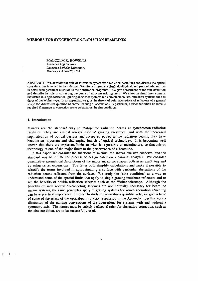
a point at distance R. From these, one can get the aijs of the paraboloid of revolution andof revolution and the bicycle—tire toroid which is an arcof the minor radius (p) rotated aboutin wave fronts reflected from a mirror. We give in Tables 2 and 3, the a,y’s for the ellipsoidMaclaurin’s series can provide some insight into the nature of the distortions to be expectedThese coefficients are associated with particular point aberrations, and a study of thethe aberration series given in the Appendix, which is therefore universal for all mirror shapes.The coefficients in this series, the aifs, are used as descriptors of the minor surface shape in
X = LaUy‘ Z
the mirror pole and whose x axis is the normal at the pole. That isMaclaurin’s series with respect to a coordinate system whose y-z plane is the tangent plane atAnother useful way to approximate a mirror surface is to express it as a two·dimensional
4. Geometrical Descriptions of Mirror Surfaces
equal to zero (see Eq. Al and Table A1).can be proved by a geometrical argument (Longhurst, 1962) or by setting F 200 and F 020and if one desires that j$ =f$ (stigmatic image), then evidently r/R = cosza. These equations
the image of a point or a line is to produce an asymmetry of the delivered image. OCR Outputoutgoing ray in the same direction for all points in the mirror aperture, so that the effect onaperture. This type of twisting of the wave front (which we call aperture defect) moves thesimilar error in the reflected wave front) that varies linearly with the position, y, in thefrom Eq. (4) that the change in ago represents an error in the mirror curvature (and hence asphere when y is positive and lag behind it when y is negative. Altematively one can also see(ellipse) value and according to Eq. (3) would cause the wave front to lead the referenceof elliptical, ago would be zero (according to Table 3), which is larger than the correctneeds an ago term of the proper value as given in Table 2. If the mirror were circular insteadimage of the axial object point, that is, a circular wave front in the image space, the ellipsethat diminishes with increasing y as it should (Fig. 1). ln order to produce an unaberratedhave r'< r, so that ago will be negative and the linear term in Eq. (4) will represent a curvatureSuppose the segment of the ellipse is chosen to demagnify the object (Fig. 1). We will then
dyz2 2a2o +6L23Oy+12lZ4Oy +..
dzx
Hence the curvature is given by
x=a2oy+a30y+a4Oy+.. (3)2 34
does not depend on z, so we may write itcylinder mirror such as one might get by bending techniques. The height x of the surface
As an example of how useful this representation is, consider the case of an ellipticalsetting j = 0 and those of the sphere by setting R = p.explained in the table footnotes. Those of the corresponding cylinders are obtained bythe apple—core toroid (an arc of radius R rotated about its chord at maximum distance p ) asa point at distance R. From these, one can get the aifs of the paraboloid of revolution and
replacement Rp —,» Rp in ag;.z2*Apple core toroid a,js are the same as those given in this table except for the
8R3l I O
O I O
4R‘p2R
1 I 0
O I O
0 I 0 I L
JI 0 I 1
TABLE 3. Bicycle-tire tor0id* agfs

V ‘ 1 is
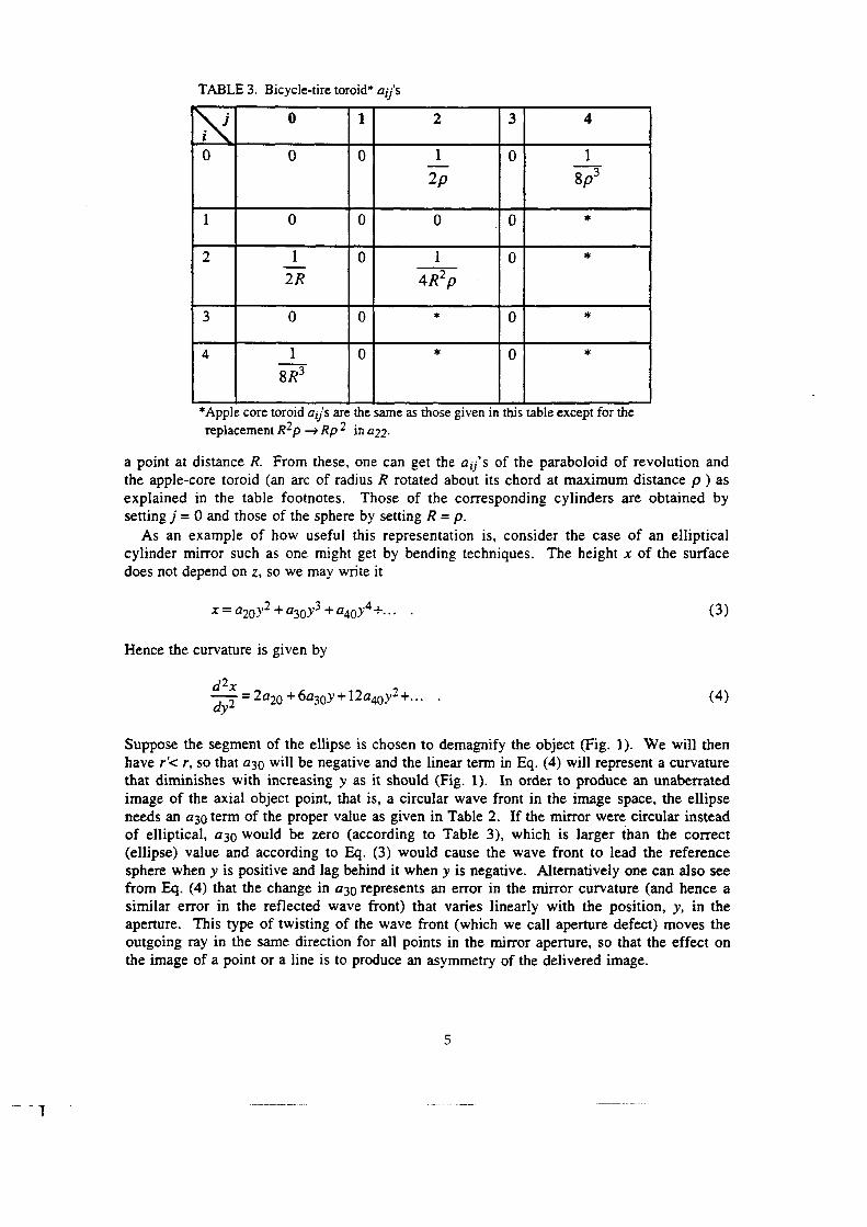
Welfofd (1965): Flgg, FH], and F]20. Thus, OCR Outputrespect to w and substitute for l from Eq. (5). There are three such terms as discussed byso we need those terms that give a Ay' proportional to Az’2, after we take the derivative with
(5)Az’=lr’(S+S') ,
applying Eq. (A5) to the astigmatism term (which dominates in determining Az') thatof the ray intersection point relative to the Gaussian image point as origin]. We know from"Ay' = kAz'2 " type of relationship in the image plane [where (Ay', Az') are the coordinatesmonochromator entrance slit. We will start by evaluating this effect. We are looking for athe tangential line image, which is the one we would normally like to use to deliver light into a
The steep sagittal curvature of the grazing-incidence toroid typically leads to a curvature ofwe will simply call a toroid.image quality that can be achieved by using a bicycle-tire toroid mirror, which from now onconics), one can use a large lap, which is a great advantage. This leads us to investigate themaintaining contact with the mirror surface at all points. Thus for toroids (but not forand finish because it is possible to move the lap in a pseudo-random motion while stillThe surface of the bicycle-tire toroid is the easiest aspheric one to fabricate with good figure
5. Toroidal Mirrors
surface we are discussing, while those that do depend on z cannot.aberrations can, in principle, always be corrected by altering the shape of the single reflectinglead to point aberrations (that is, those that do not depend on the z coordinate). Suchmirror from the ideal ellipsoid of revolution. It is important to recognize that incorrect a,y’s
Similar arguments can elucidate other types of image defect due to other departures of the
Figure l. Ellipse geometry and notation.
36
Object Image
X¤Y¤
or opposite signs. OCR Output
formed by displacing either curve along the other as shown in (c). The two effects can have either the sameat the entrance slit, called "astigmatic curvature" by Beutler. In practice the two are combined into a shapecalled "enveloping curvature" by Beutler, and (b) shows that of the astigmatic focal line due a point sourceFigure 2. The two types of line curvature. (a) shows the one due to the finite length of the entrance slit,
(cl
(bl
(al
Using the above equation for fs, this becomes
(7)
AMC = —-·:——#+v-(+$)2(S + S r r r r11 1 , t 0: S S 2 S + S LJ$’22 {2[)F 102 and F1]; from (Noda, 1974), we now haveshown in Fig. 2 (Welford, 1965). Retuming to Eqs. (5) and (6) and the Appendix, and takingenveloping curvature by Beutler. In practice, both may be present and would be combined asdirection (for example, a slit). The latter type comes from Fwz, with z ¢ 0 and was namedBeutler (1945). There is another type that arises when the source has a finite extent in the 2some astigmatism. This leads to a type of line curvature named astigmatic curvature byWe consider the case in which the source is a point in the symmetry plane (z = O) and there isNote that none of these terms depends on z (only on z'), so that this is still a point aberration.
6) (. wlZF + IF + F 120 W 111 W 102r' 8 l ’ =—;——>’1c cOSa8w(2

V t' 1 t "’
BOO cosaélw 2300 12 ( ) OCR Output' 8 {1 A ’ = L- - 3w} F
defect. The ray aberration Ay 'ggg is given byWe turn now to the next-largest toroid aberration after the line curvature, namely, aperture
when a toroid will work best is when it is acting as a weak lens.feeling for the amount of line curvature to be expected and shows that, in general, the timewhich is the sag of the toroid in the minor radius direction. This gives a useful "worst-case"
(1 1)Ayic = it
to
being the furthest from unity magnification. At grazing incidence (sina =l), Eq. (9) reducesstigmatic, and the source point is at infinity (M = O). This is the worst case for using a toroid,for using toroids in practical situations. Suppose that the radii are chosen for the image to be
We can derive a useful rule of thumb from Eq. (9) that helps in thinking about possibilitiesmagnification value where it passes through zero.also. It is also significant that the line curvature has opposite signs on opposite sides of theso that there is always an M S that gives zero line curvature. This equation is potentially useful
1+ M ,(10)M , = 4
2M
us that the curvature of the tangential focal line will be zero provided thatin the tangential and sagittal planes. Thus M ,= r',/r and M S = r',/r. Equation (8) now tells
To see the usefulness of Eq. (8) let us define separate magnifications and image distancesmagnification has several practical applications in beamline design.aberration), as we discuss below. The good·quality image provided by a toroid at unityfurther than eliminating line curvature. It also eliminates the aperture defect (F 300a better approximation there than elsewhere. The advantage of unity magnification goes(minimum) values in the Y-Z plane. Therefore, a toroid, which has two constant curvatures, iscurvatures of an ellipsoidal mirror vary with position on the surface but take stationaryan ellipsoid with the mirror pole in the symmetric position in the Y-Z plane (Fig. 1). Now thesince the mirror surface needed for aberrationless imaging of a point at unity magnification isline—curvature aberration is evidently zero for unity magnification. This is sensible intuitivelychoices of the conjugates in both Eq. (8) and Eq. (9). When there is a stigmatic image, the
It is noteworthy that the undesirable broadening Ayjc, passes through zero for particular
— M -1 ylc 2 D ( )l lz sin tz A ' =-—
important special case is the stigmatic image (jf, =j). Using j} = (1/r+1/r') 'I, Eq. (8) becomesof the curved line image in the general case where some astigmatism is present (I} ¢j$). Anwhere M (= r/r') is the magnification. This a useful equation for calculating the depth (sag)
(8)Ay;C=...3M+]..._I2 * a}iLq[&] 4fS fs

image of an erect object is formed in a plane steeply inclined to the outgoing principal ray. OCR OutputThe lowest-order aberration is a familiar one from grating theory where it is known that the
optical quality of the beam.required to deliver x rays at modem synchrotron radiation facilities without degrading thethe best figure and finish accuracy. It is often the only way to get optics with the tolerancesparticular value of the radius. The use of spherical optics is now established as the way to geteven easier than a flat. From a fabrication point of view, a flat is like a sphere with aeasiest surface of all is a sphere with a loose tolerance on the radius, which is in many ways
Just as toroids are easier than conics to fabricate, so spheres are easier than toroids. The1988) or to condense a beam into a monochromator entrance slit.but is now more often used in a demagnifying geometry to form a microprobe (Underwood,used in a magnifying microscope configuration in the 1940s and 1950s (Kirkpatrick, 1948),stigmatic toroid at the same grazing angle and is easier to make with good tolerances. It wasin two dimensions as shown in Fig. 3. Such a scheme has less aberration than a singlesecond spherical mirror focusing in the sagittal plane of the first to achieve a focused imagefirst sight, this appears to be a disadvantage, but in fact it is very useful because one can use asagittal plane and the rays continue to diverge (or converge) at the same angle as before. Atastigmatism is essentially complete. That is, the mirror achieves almost no focusing in theln fact, when spherical mirrors are used at extreme grazing angles (a few degrees or less), theR. In view of this, a stigmatic image is not obtainable using a spherical mirror unless tx = O.The theory given so far for toroidal mirrors applies to spherical ones in the special case p =
6. Spherical Mirrors: Kirkpatrick-Baez Systems
above, it vanishes at unity magnification or, more generally, it is zero on the Rowland circle.
use on an undulator beamline with a monochromator that has an entrance slit. As we notedaperture defect is the dominant aberration in spherical condensing mirrors such as one wouldthat half the rays have aberrations less than one-quarter that of the marginal ray. Theray and is thus a rather pessimistic estimator of image degradation. One can see, for example,involved. lf w is the mirror half-width, then this equation gives the aberration of the marginalwhich applies equally to spherical and toroidal mirrors since the sagittal properties are not
yw us)% ·Aé=§
of thumb
or in the common case of grazing incidence (sina =l) and M<<l, we get another useful rule
’ 2 R(14)Ayéwzw
éz sin0:(M—l)
the tangential focus so that we can apply Coddington’s equations, this reduces toSpecializing to the case of a toroid for which (230 = O and :120 = 1/2R and assuming we are at
A `, _ J 2 . , )3OO —-:W {Sli'] G(M—1) COS(Z·+··2020 ·4l' 0301 1 (;;;)
which leads, in the general case to

i- ‘ 1 FT
10 OCR Output
does extend up to 1.5 meters but with some worsening in cost, weight, and tolerances forlimit is the difficulty of making mirrors larger than about one meter long. Current capabilityperformance for the spherical condensing mirrors that are now quite widely used. Anotherthe aperture defect, which we have already discussed and which is typically the main limit to(Hogrefe, etal., 1986). The largest aberration for long·radius spherical mirrors is thereforeEq. (2) and the line image becomes essentially straight as one would expect [see Eq. (8)]Without the steep curvature of the toroid we now have p large and therefore f, large bysynchrotron source, then the defect becomes tolerable and the spherical mirror is very useful.fields. However, if one only wishes to image a small distant object such as a slit or thein popularity of the Kirkpatrick-Baez microscope as a device for imaging extended objectavoiding the loss of performance caused by this defect was partly responsible for the declinethe grazing angle: obviously a very unfavorable condition for imaging. The difficulty inwhere ag is the grazing angle of incidence. The angle Q is seen to be always smaller than
Br' , M +1,3,, G = KQ) = ESQ
the principle ray is given bycondition F 200 = 0 and noting that the tangent of the angle 9 between the focal plane anddescription. Nonetheless, the behavior can still be described by considering the focusingplane field aberration and there is no field coordinate in the symmetry plane in the Nodaobliquity of field, is not represented in the listing in the Appendix because it is a purely inOne example of such an inclined focal plane is the Rowland circle. This defect, known as
planes perpendicular.Figure 3. The layout of the two spherical mirrors in the Kirkpatrick-Baez microscope with their tangential
•’ object
Image /•

l" _ l S Ti
11
,, . X0=iGwl·YO2 fg%
The coordinates of the pole of the mirror are
bz = a2l — e(z)(16) OCR Output(2ae)2 = rz + r'2 —2rr’cos 201
Za = r + r'
the geometry of Fig. 2:quantities r, r' and tz by means of the focus—directrix definition of the shape of the ellipse andellipse parameters a, b and the eccentricity e can be expressed in terms of the user-specifiedX2/a2 + Y2/b2 = l where a and b are the semi-major and semi-minor axes, respectively. Theconjugates r and r' and the included angle 20: (see Fig. 1). The equation of the ellipse is
First consider an elliptical mirror whose action is defined by the object and imagethe surfaces of revolution, but the polishing problem described above still remains.the surface to be manufactured as a flat. Diamond tuming is an acceptable way to generateopinion, is to use bending, which is only applicable for an elliptical cylinder but does allowThe most promising strategy for obtaining an ellipse of high accuracy, in this author'swere similarly limited in resolution by the fabrication tolerances of their parabolic mirrors.resolution. The plane-grating monochromators at the National Synchrotron Light Sourcethose systems, and their manufacturing tolerances determined the achievable spectralcategory. The ellipsoidal mirrors in the SX700s have always been the limiting component ofthan using a large lap. The result is that it is hard to get good-quality mirrors in thisan approach gives much worse errors in figure and finish and with greater effort and costpolishing, so one must have recourse to zone polishing using a small or a flexible lap. Suchrotation in a single direction for the surfaces of revolution. This is not sufficient for goodsurface without losing contact is a linear motion in a single direction for the cylinders andcontact with any of these surfaces, then the only possible motion of the lap relative to thediscuss it further in the section on the sine condition. Secondly, if one puts a full-size lap inobject point, and other points are imaged poorly. This is not a fatal disadvantage, and weuseful than they might appear. Firstly, the ideal imaging property only applies to the axialwith one conjugate equal to infinity. However, it often tums out that these cases are lessobvious applications and, as we have seen, can often be regarded as a special case of an ellipsepoint·to-point imaging. Paraboloidal cylinders and paraboloids of revolution also havechoices for many applications as the two-dimensional and three-dimensional surfaces of exactSX70O plane-grating monochromator (Petersen, 1982; Nyholm, 1986). They are obvioushave been used on beamlines. For example, both have been used as focusing mirrors for theMirrors shaped as elliptical cylinders and as ellipsoids of revolution are both of interest and
7. Ellipse- and Parabola-Shaped Mirrors
undulator beams.
photon energy is above a few-hundred eV. However, such systems are well suited to use withKirkpatrick-Baez systems used on bending magnets are rather severely restricted when thefigure and finish. The consequence of this size limit is that the horizontal collection angles of
L . ,
12
, s1n¢ cpp(23) OCR Output—?i“‘°—@
1976) states that for all rays one must haveincidence systems with an axis of symmetry. Thesine condition (Abbe, 1879; Welford, 1962,We tum now to the role of the sine condition in determining the aberrations of grazing
8.1. GENERALARGUMENTS
8. The Sine Condition and Coma in Axisymmetric Grazing-Incidence Mirrors
1968; Combleet, 1984; Korsch, 1991).in the literature that deal with conic and similar mirrors at a deeper level (Brueggemann,fronts in a more complete way. In such cases, the reader is referred to one of the treatmentsa simple shape, this situation changes and one needs to understand the behavior of the waveFor applications in which a high-resolution image is required, as opposed to reproduction ofquite unsophisticated, and one has little need to understand the geometry in a serious way.
The applications of conic mirrors that one encounters in synchrotron practice are usuallysystems.
for paraxial design, and 6 for making coordinate transforms between the X-Y and x-yand the angle 6 between the tangent at the mirror pole andthe x axis is cot -*:1. Rp is useful
P cos3 0:22 ( )O R =-——
2a
Rp is given by
(21)X0=a0tanl0z YO=2aOtana
while the pole of the mirror is the point
do = rcos‘ a
4a0X, where ag is the semi-latus rectum. The latter is given byFor a parabola, defined by the focal length r and included angle 2a , the equation is Y2
(19)6 = cos-] g(g) e
and the angle 6 between the tangent at the mirror pole and the x axis is given by
,18()R =——rrr3/2
than r'. The tangential radius of curvature Rp at the pole of the mirror is given bywhere the square root is +, 0, or —, depending on whether r is greater than, equal to, or less

l' ‘‘l i TF
13 OCR Output
the ray intersection point P be the circle AB is equivalent to the sine condition.the object and image points O and I. Draw a circle on AB as diameter. The requirement that the locus ofFigure 4. The geometrical form of the sine condition. Let A and B be harmonic conjugates with respect to
li-\——V—>|
N ~\
\—i P~\ /
systemUptlcal / \— Principal surface
corresponding outward rays to I should be the sphere AB. This locus, called therequirement that the locus of the intersection points P of the inward rays from O and thesphere with AB as diameter. It can be shown that the sine condition is equivalent to theThat means that B divides OI extemally in the same ratio that A divides it intemally. Draw aconstruct a new point, B, such that A and B are harmonic conjugates with respect to O and I.I lying on the axis and distant u and v, respectively, from the center A of the system (Fig. 4),
The first important idea can be expressed as follows. Given object and image points O andfollows and discuss the possibility of applications to synchrotron-radiation systems.implement the ideas effectively became available. We give a distillation of these ideas in whatfirst described by Wolter in a landmark paper in 1952, long before the technology needed tosystems are widely used in x-ray telescopes. The main ideas on which they are based were
Of course, there are grazing·incidence systems that do have a symmetry axis. Suchthey are not corrected by obeying the sine condition.aberrations of greatest interest to us-line curvature and aperture defect—are not really coma,aberrations is discussed further in the Appendix. Here we only emphasize again that since thecorrected by obeying the sine condition or any derivative of it. The proper naming ofplane of symmetry (which have been loosely called coma by some workers) cannot bepointed out by Underwood (1992), the aberrations of grazing-incidence systems with only ameasured from the symmetry axis and is defined, for example, by Born and Wolf (1980). Asstrictly the aberration of the axisymmetric system, which depends linearly on the field anglesystem free of spherical aberration is also free of coma. The coma involved in this theorem isand cp], are the same thing in the paraxial regime. Satisfying the condition guarantees that awhere ¢ and ¢'are the angles of the inward and outward rays to the symmetry axis and gb,

14 OCR Output
radius of the circle Rc must be given byinclined to the axis by 5, the image will be a circle centered on F, and, from (25) and (26), theBy considering other reflection points on the ring PlP2P3, we can see that, for the rays
(26)y = r'5
while F2 has
cos yry=—- . (25)
i‘?
same, and both have
where r' = PIF and the angle 21;/= PIFP3. If we now take 5 << 1;/, Fl and F; become the `
1_...32cos(t;1+5) cos(1;1-5)(24)E?.§. Fp:.l§1rL‘§.. pp=,*mn5
is above F. From the geometry of the figure we can see thatprojection, in which the ray is seen through P2, it appears undeflected and arrives at F2, whichdownward and will meet the focal plane at F2 and F3, which are both below F. In the5 below the axis-parallel ones, the reflected rays from P] and P3 will both be deflectedThus, there is no spherical aberration. For the rays (shown dashed) that enter at a small angleparallel to the axis, shown as thin lines, the image is perfect and the rays unite at the focus F.consider the image formed by a thin ring of reflecting surface P]P2P3. For the rays that enterFirst consider a paraboloid of revolution being used to focus parallel light (Fig. 6) and
8.2. CALCULATION OFTHE COMA CIRCLE
principle can be used to correct it.plausibility arguments showing how coma is produced and how the double-reflectionbeen widely used in recent years, particularly as x-ray telescopes. In the next section, we givereflection as in the Wolter telescope and microscope systems (Fig. 5c). Variants of these havesimilarly high degree of coma correction in a grazing-incidence system is to use a doublecondition. A high degree of coma correction is therefore expected. One way to achieve aitself, but now it closely approximates the spherical surface required to satisfy the sinethe foci but this time in normal incidence. In this case, the principal surface is still the mirrordifferent segment of the ellipse (Fig. Sb) again operating with the object and image points atsine condition grossly and can never be coma-corrected. On the other hand, consider a1978). It is obvious from this that any single-reflection grazing-incidence mirror violates theto the spherical surface that it would need to be to obey the sine condition (Underwood,principal surface in this case is the surface of the mirror itself, and it is roughly perpendicularwith object and image points at the foci of the ellipse (Fig. 5a). We immediately see that the
Suppose now that we have a segment of a single grazing·incidence ellipsoid of revolutionplane through A normal to the axis will be a reasonable approximation to the sphere.point of view of grazing-incidence systems, which generally have small deflection angles, the"Knieflache" by Wolter, is usually translated "principal surface" in English. From the

l" T
15 OCR Output
that the radius of the circle is actually given byThis has been an approximate treatment (Howells, 1980). Wolter's more accurate one reveals
.. 2 cos up (27)Rc ='6 l r
in which the principal surface is a much better approximation to the desired surface than in (a),surface almost coincide and thus lead to much higher quality imaging. (c) Double-reflection Wolter systemAnother single-reflection geometry but now at near normal incidence; the mirror and the desired principalis roughly perpendicular to the principal surface (shown dashed) needed to satisfy the sine condition. (b)Figure 5. (a) Single·reflection imaging geometry in which the principal surface is the mirror itself, which
Hyperbola
Ellipse
ze<¤>LZ- Principal surface
. EllipseAct al rinci al surface U p p -7
(blsurfacesprincipalDesired
Ellipse
(a) Actual principal surface

l` ` `I
16 OCR Output
= O.
well-corrected coma. For this case, the value of 1;/is roughly 180° leading to (1 + COS1;/)/COS\;/It is also clear from the above treatment that the normal-incidence conic has the expected
coma (Welford, 1962).once round the ring P]P2P3, the ray traces out the circle twice, which is again characteristic ofcircular aberration figure in the focal plane. Furthermore, each time the reflecting point runswith the field angle 6 and also because each circular zone of the aperture contributes a
That this aberration is really Seidel coma can be seen from the fact that it varies linearlysuch as t0 pass through the paraxial image point.conclusion is that the image of an ajjiaxis point is a circle centered on the axis with a radiusRc = (r7r)A or A times the magnification. Moreover, (1 - COSI;/)/COSW = O so s = 0. TheSince 1;/ is small for grazing-incidence systems, we have (l + COSI;/)/COSl;/‘-= 2. Consequently,finite distance r from PIPZP3 and displaced a distance A from the axis so that 6= A/T.Now consider a grazing-incidence ellipse in the same geometry but with the object point at a
S=_ (29)r tanl— cosw5() 2 cos1|/
and that the center is shifted off axis by s where
RC= (28)r’tan6l+cos1[p) 2 cos 1;/
reflection, grazing-incidence mirror with a symmetry axis.Figure 6. Definition of the points F, F], Fl', F2, F3 used in explaining the origin of coma in the single
_
1 — -· - _ _
K IP`\ I
i FP1=FP2=FP3=rI
F3 \\1 ' \\
___
. rsin5 - /"·———~--_<>*+—/— -/
’F2 /; ,1 //
5 /’/ 8’/I Z / ////////I //
/ /

17 OCR Output
nearly axisymmetric) shape is implemented over a segment of angular width Q = l6.5°Figure 7. Explanation of how coma leads to a "bow-tie" image when a mirror with an axisymmetric (or
Gaussian image
\z , ` `/\ Z { s § ' {
'""''“''` F ’":`'""`'```Z II
•—•-—·————-—·-11-ri-••!*·•!'.§1*•*•·O*•*
/ ~ ` _I` ` `
Actual “image”
behavior becomes significantly different for magnifications far from unity.aberrations are no longer strictly Seidel coma. Although there is no sudden change, thecontinues roughly similarly, but the symmetry of the system has been broken and theimage lying on it. However, as the magnification departs from unity, the behavior initiallytoroid, which does have a type of symmetry axis with the center points of the object andFig. 7. Note that this behavior also follows the theory closely for a unity-magnificationsynchrotron radiation sources often are, the result is a "bow-tie" image as explained inpoint. When the object is extended in one direction much more than the other, asbe an arc of the image circle of angle 2Q passing through the paraxial image of the objectrevolution that subtends a maximum angle Q at the axis. The image of an off·axis point willwidespread. Consider a unity-magniiication mirror comprising a segment of an ellipsoid oftroublesome at synchrotron radiation facilities before low-emittance electron beams becameincidence mirror, we can understand the well-known "bow—tie" shaped image that used to be
With this insight into the dominant field-angle-dependent aberration of the single grazing
18 OCR Output
proposed, and we can understand their operation in terms of the principles described above.mirror pairs in general are not useful. Indeed, there are already several examples existing andprobably do not have a role in beamline systems for the time being. This is not to say that"lens" is an oversimplification of what is needed. The conclusion is that Wolter opticsgrating monochromators must be combined with those of the grating, and the use of a betterbeamline component. Moreover, the aberrations of focusing and collimating optics inhigh cost of a Wolter system of sufficient optical quality being considered acceptable for asystem. However, even when such advantages are taken into account, it is hard to imagine theilluminating crystal monochromators which could probably be avoided by using the Wolterand vertical divergences of the beam from a bending magnet, and this is a disadvantage inwould have certain advantages. For example, even a perfect paraboloid mixes the horizontalfocusing system for a monochromator. This is a different case and the higher-quality "lens"
One might ask whether there could be a role for the Wolter system as a collimating oraccompanying systems.
and would scarcely repay the investment needed for an extra aspheric mirror and all itsthe flux that could pass through a slit would hardly make up for the losses of the mirror itselfsystem as a condenser would be to eliminate the bow·tie effect, but as Fig. 7 shows, the gain inis not significantly enlarged. The only useful improvement one would get by using a Wolternot accurately reproduced in the image is unimportant provided the overall size of the imagefact that detail features within the object (which is usually the synchrotron source or a slit) areuseful in x-ray microscopes. However, beamline mirrors are generally condensers and theWolter system is useful in imaging systems such as x—ray telescopes and may eventually begeneration of improved beamline mirrors. The kind of high—quality image provided by aunderstanding of grazing—incidence minor systems, it does not provide a blueprint for a new
Although this discussion of the Wolter double-reflection principle contributes to ourthe principal surface for the double-reflection system as shown in Fig. 5.normal-incidence conic. This is in accord with expectations based on the sine condition andallows one to design grazing-incidence systems with image quality similar to that of theintroduction of the double reflection brings about a large reduction in the aberration andwhereas the corresponding factor in Eq. (28) for Rc was approximately equal to 2. Thus theEquation (31) for R,. has the factor (1 —cosy1)/cost;/= 0 for a grazing-incidence system,
RW 2 (31)@(1121) 2 cos 1;/
a Wolter system, has a radius RW given bywhile the ray through P2 continues to have y = r'6, so that the aberration circle, in the case of
cos 1;/(30)y=+.[._i
downward and arrive at Fl' as shown in Fig. 6. The rays through P] and P3 now havebehaves as before, while the rays through P1 and P3 are now deflected upward by 6 instead ofjust in front of and just behind the joint. Considering the same three rays, we find that P2F2P1P2P3 contains the joint between the two reflectors and imagine the rays to be reflected twice,elucidating the principle of the Wolter double-reflection system. Suppose that the ringWe now retum to the analysis of the focusing system shown in Fig. 6 with a view to
9. Mirror Pairs in Wolter Geometry

V i T
19 OCR Output
and line curvature), while (b) and (d) are not.configured for approximate cancellation of point aberrations depending on an odd power of w (aperture defectingoing side; (b) and (d) satisfy the sine condition in this sense. On the other hand, (a) and (c) arecondition grossly because the angle to the axis decreases at the outgoing side when it increases on theFigure 8. Four possible ways of combining two toroidal mirrors in pairs: (a) and (c) violate the sine
(d)
tc)
(bl
(al
ideal paraboloid), we would expect the wave front emerging from the first mirror to bemirror is too weak on the upstream side and too strong on the downstream (compared to theFig. 8a and take F 300 as an example. Based on the fact that the circular curvature of thesymmetry axis and the sine condition has an exact meaning. First consider the toroid inexpect a high degree of correction to be achieved only if there is an exact or approximateanalyze this possibility in terms of wave-front errors. Even for the field aberrations, wenot be improved by obeying the sine condition, but they can still be made to cancel. We willdisobey it (¢' decreases when dg increases). The dominant point aberrations F 300 or F12;) willwhich tend to obey the sine condition (¢' increases when ¢increases). Others radicallyChrisp, 1983). Figure 8 shows several contigurations involving two identical toroids, some oftwo mirrors or a mirror and a grating (Pouey, 1981, 1983; Aspnes, 1982; Hunter, 1981;There have been several studies carried out to identify the best way to combine the action of
10. Mirror Pairs in General

r- ‘ 1 ‘—·
20 OCR Output
Sciences, of the U.S. Department of Energy, under contract DE—AC03—76SFOOO98.This work was supported by the Director, Office of Energy Research, Office of Basic Energy
Acknowledgements
advantage of conics.likely to be larger for a conic than a toroid and will often more than outweigh the aberrationimaging surfaces. However, it is important to recognize that manufacturing tolerances arethese have no point aberrations, whichever way round they are, since they are the ideal point
One can obviously design mirror pairs analogous to those in Fig. 8 using conics. Naturallyto explore further can refer to the paper by Namioka et al. (1983).
This discussion does not exhaust the possibilities of two-mirror systems. Readers wishingnormally be one that corrects the point aberrations.small source sizes of modem storage rings, the best system design for a condenser willone. On the other hand, the potential damage due to point aberrations is unlimited. For theeffect that enlarges the short dimension of the synchrotron source `or slit to equal the longRoughly speaking, the worst that can happen due to a field aberration is an extreme bow·tieseparately and their relative importance depends on the source size and aperture size.vanish at that value. As we have seen, the point and field aberrations must be consideredaberrations, line curvature and aperture defect, which would normally be dominant, happen tolimited to unity or infinity. The choice of unity has special consequences because the pointinterpreting the results given by Aspnes because the toroids used had magnification valuessine condition reported by Aspnes (1982) and Hunter (1981). One has to be careful in
There are some similar comparisons between pairs of mirrors that do and do not obey thenot be met in real beamlines.
magnitudes (although maybe not the same signs) in each mirror. This is a condition that maytogether that each ray is reflected at aperture coordinates (w, l ) with substantially the sameof arguments depend on the aberrations being small enough and the mirrors close enough8b) can be verified by ray tracing for particular geometries. It is noteworthy that these typesindeed gives a better image of the axial point than the inverse configuration (shown in Figcanceling for the same mirror configuration (Fig. 8a). That the configuration in Fig. 8acorresponding to line curvature (which also depends on an odd power of w) will also be selfstrongly disobey.: the sine condition. Similar arguments show that the wave-front errorsreflection, provided its direction is as shown in Fig. 8a. Note that this is the direction thatsecond mirror, we see that wave-front errors of opposite sign will be introduced by the secondsphere above the principal ray and lagging it below. If we apply the same argument to thetwisted, as described earlier, by an amount proportional to w-* and to be leading the reference

21 OCR Output
Figure A1. Coordinate system used discuss the optical path function analysis (after Noda, 1974).
=El:jk(a,T,Z)+Eiik(B,T,,Z/) ,
possibility that the grating is a holographic recording. This leads tosubgroup of the expressions for the F ;ik`s. First we reject the parts that represent thethey do not represent aberrations. For the study of mirrors, we can use a still more restrictedomitted, being equal to zero by symmetry, and terms that have i = j = 0 are omitted because+ k S 4) and are exactly those given by Noda et al. Those that have j + k = odd have beenrepresents a particular geometrical optical aberration. The terms go up to fourth order (i + jand k are the powers of w, I, and z (or z' ) in the series expansion of F , each term of which100 term. F is the actual path length AB, and w and l are defined in Fig. Al. In F {ik, i, j,We have included the 102 term explicitly, whereas Noda ez al. included it implicitly in the
(Al)
22%4%2£2%3%2+%WlF22O +IF04O +WF2O2 +·lF022 +lFO3l +WlF2l 1+..- · 4 F- WFIOO +wF1O2 +]},:0]] +:W FZOO +5l F020 +5W Fm +:wl F120 +wlF]1] +:W F4OO
I 2 I 2 1 3 I 2
According to Noda etal. (1974), the diffraction·grating optical, path function is given by
Appendix. The Optical Path Function Expansion for Gratings and Mirrors

r · w 2 me
22
JT 404Tsin‘ 0: ·· 80COS (Z
4dgO · T-4030 Slll 2a4 I 2
r
Tsina *"""" ’ 2(I30 Cosa
r
2Ssin‘ 0: -7- - 4a22 cos a
0 I 4¤z¤¤¤z—T5·2¤i2Si¤2¤ .I 0
r
- smc S s`ntz 0 I —L-—2a]2c0sa
°l— - Xara coscx OCR OutputOI 4 2 #$2 £
TABLE Al. Values of Ei;O(<1,r,0).
the mistake of regarding z or z' as directly analogous to the "axisymmetric" type of fielddepend on it, such as Seidel coma, have no analog in the present study. One should not makemeasured from the axis, no longer exists in the absence of an axis and so aberrations thatcompletely different. In fact, the conventional field angle or field coordinate, which would behas only a plane of symmetry rather than an axis, the notion of field coordinates isthe same as the aperture coordinates of an axisymmetric system. However, since our systeman axisymmetric optical system. The aperture coordinates w and I, for example, are basically
The terms in Eq. (Al) have some similarities with the terms in the aberration expansion ofparameters have been discussed in detail for some important surfaces in the main text.S 'and T ’ are also defined and are the same as S and Texcept that r is replaced by r'. The aij
(A4)gg2T=-;--—2a20 com s=:-zaozeom
The function E;j0(¢2, r, O) is therefore tabulated in Table A-1, which uses the notations
FUD = EU0(a,r,O)+ Eii0(-¢1,r',O) (A3)
0. We also know that from the law of reflection that B = -0:, so that (A2) becomesconsider a point source located in the symmetry plane of the mirror. This means z = z' = 0, kwhere Eyk is the expression given in Table A1. For a beamline mirror, it is often sufficient to

23 OCR Output
and
<A5>Ayiio = r' BF ——(—] cosa Bw UO
(displacements from the paraxial image point), which in our notation are known as Ay'andapproximation. For each term of the aberration series, we calculate the ray aberrationsparticular aberration. We now proceed to address that issue in the geometrical opticsthing, which is the extent of degradation (blurring) of the image that will be caused by anyOf course, the treatment given so far does not enable one to calculate the most interesting
F211 211 aberration
F031 031 aberration
F022 022 aberration
F202 202 aberration
Higher-order astigmatismF040
F220 220 aberration
F400 Spherical aberration
F111 Line curvature
Line curvatureF120
F200 Aperture defect
Astigmatism (sagittal defocus)F020
F200 Tangential defocus
Law of reflection in the sagittal planeF011
F102 Line curvature
F100 Grating equation
only when the analogy is fairly complete. The following system of names is proposed:section on the sine condition). Therefore we propose to continue to use traditional namesUnderwood (l992).that this can lead to important errors in the treatment of coma (see theThe present author has been among those guilty of this. It has been pointed out bythere could be no similarity in their dependence on the field coordinates, as explained above.aperture coordinates as conventional coma, have been referred to as "coma," even thoughsystem. For example, the F 120 and F 300 aberrations, which have the same dependence on the(Al) based on only partial similarities to the corresponding aberrations of the axisymmetricsynchrotron-radiation community of giving traditional names to the aberration terms in Eq.
In light of the above, it is perhaps unfortunate that a tradition has grown up in the
coordinate.
and none of our coordinates w, l, or z (or z') can be identified as a conventional Heldterms. But these terms are both symmetry-forbidden. There is no coma in the usual sense,same error might lead us to look in Eq. (AI) for terms like wz or wlz to End the coma3zsymmetric system, the restriction to the tangential (symmetry) plane implies z = z' = O! Theaxisymmetrical system still has a field coordinate measured from the axis, but for the planespecialized to two dimensions so that only their tangential planes are considered. Thecoordinate. To scc thc error of this, consider the case in which both types of system are

V ‘ `[ ‘ _“OCR Output
24
mirror. The rays travel from left to right.This figure shows the pattem of intersections of the rays with the tangent plane at the pole of the toroidalFigure A2. Layout of the 5 >< 15 ray points and their plot labels used in the ray trace shown in Figure A3.
Position (cm)
-10 10
.50
general case, we approximate Ax' and Ay' asexplain the general features of the ray traces in terms of the lowest-order aberrations. In theEqs. (A5) in determining the pattem of ray intersections in the receiving plane, we try toaberrations up to very high order are accurately represented. To illustrate the action ofFig. A3. The rays traced are shown in Fig. A2 and are done in double precision, so all
As an example of the application of Eqs. (A5) and (A6), we show some ray traces inas provided, for example, by McKinney and Palmer (1987).approximation. For very fast systems of f-1 and faster, more complex expressions are neededray. For the slow systems involved in grazing-incidence optics, Eqs. (A5) give an excellentinvolved in rotating the exit pupil so that it can be perpendicular to the outgoing principalfactor 1/coszz in the first of Eqs. (A5). This arises simply from the coordinate changethe case of grazing incidence, which differs from the standard case of axial symmetry by theexample, by Welford (1962) and Bom and Wolf (1980). Neither of these authors includesEquations (A5) are central to the geometrical theory of aberrations. Proofs are provided, for
(A6)Ay'=ZAy£i0 and Az'=ZAz$0
when done deliberately) is possible and is sometimes useful.This means that partial or total cancellation of aberrations (known as "aberration balancing"The total ray aberration in the Ay' (Az' ) direction is the algebraic sum of the Ay'Ug's (Az'Ug's ).
U, , rAZ,. : r —. Oa) [al no

25 OCR Output
transverse scale so that the residual aberrations can be seen.the line image indeed becomes straight as predicted. Figure (d) is the same as (c) but with an expandedthat the value of p has been increased to the value (0.l744974840 m) given by Eq. (10) to demonstrate thatdownstream of the focus and with a 5 x 31 ray pattem. In Figure (c) the system is the same as in (a) exceptplane for the above system. Figure (b) shows the image from the same system but in a plane 15 cmextreme precision for calculated numbers input to the ray·trace code. Figure (a) is the image in the focalmm2. R and p are calculated to give a stigmatic image, and we follow the standard practice of usingp = 0.1 163316560 m. The mirror area (tangential x sagittal), measured in its tangent plane, is 300 x 40parameters of the system for the image shown in (a) are: r = 10 m, r' = 2 m, a = 88°, R = 95.55123612 m,conditions. The 5 x 15 pattem of incoming rays and their plot symbols are shown in Figure A2. TheFigure A3. Ray traces of the images of a point source produced by a toroidal mirror under various
Position (mm) Position (mm)
-5 0 5 -0.3 -0.2 -0.1 0.0
. 1 (¤>(¤>
Position (mm)Position (mm)
-2.0 -1.5 -1.0 -0.5 0.0-1.5 -1.0 -0.5 0.0
-1.0
-0.5 •··°"$
0.0
<il"`W¢n
O·-°__;\0.5
(b)(a)1.0

l" ` T ` T`
26 OCR Output
hallmark of the F 220 effect.line curvature with equal sizes but opposite signs for positive and negative values of w: theshould be, since we are now in focus. Moreover, we see another aberration that gives a slightreveals that the only horizontal shift along the Ay' axis is the wz one (aperture defect), as itcorrectly delivers a straight focal line. Examination of the expanded diagram in Fig. A3(d)(long focal line) and no defocus, and we see clearly that application of Eq. (10) in choosing pthe Ay' axis are intelligible on this basis. Tuming to Fig. A3(c), we see a large astigmatismStarting from the plus sign at (O, 0), we can see that the sizes and directions of the shifts alongwe have two effects determining Ay', a w effect (defocus) and a wz effect (aperture defect).but it continues to show, basically, a family of parabolas. In the symmetry plane (l = Az = O),i.e., Az' proportional to I3. Figure A3(b) shows more aberrations because now FOQQ, F 200 ¢ O,at which Az' increases with l (measured in plus-sign intervals) shows it to be an F040 effect,at low l, but at high l, some higher—order aberrations give an increase in Az'. Study of the rateEq. (A7) predicts that Az' = 0. The line traced out by the plus signs does show this behaviorseen in Fig. A3(a). On the other hand, when F020 = w = O (the plus signs in Fig. A2),with increasing w and a Ay ’—directed shift proportional to wz. Most of these features can beA3(a), Eq. (A9) predicts a family of parabolas, each with a semi·latus rectum that increasesF O20 = F 200 = O representing a stigmatic focus, which is the condition prevailing in Fig.Equation (A9) shows some of the characteristics we see in the ray traces. For example, when
—+F w+—F0Ow 2 2°° * 3 (A9)' Ay’=— F ”°cowl 2,·2(g,,,, + gww)1 2Aziz
(p << R). Substituting for lfrom (A7) into (A8) we getcurvature aberration. This is valid provided we are dealing with a steeply curved toroidNotice we are ignoring the second and third terms in Eq. (6) in our representation of the line
(A8)A ’=——F l‘+F w+-F w N 120 200 sooT, I com [2 3 2] 2
and
(A7)Az' = r'[F02Ol + 1·;20w1]

27 OCR Output
R6ntgenstrahlen," Ann. Phys. 10, 94-114 (1952).Wolter, H., "Spiegelsystem Streifenden Einfalls als Abbildende Optiken fiirWelford, W.A., Geometrical Optics (North Holland, Amsterdam, 1962).
292 (1976).Welford, W., "Ap1anatism and Isoplanatism," Progress in Optics, edited by E. Wolf, 13, 268
edited by E. Wolf, 4, 241-280 (1965).Welford, W., "Aberration Theory of Gratings and Grating Mountings," Progress in Optics,
Multilayer Mirrors," Nucl. Instrum. Methods A266, 296-302 (1988).Underwood, J.H., A.C. Thomson, Y. Wu, and R.D. Giauque, "X—ray Microprobe UsingUnderwood, J.H. (private cornrnunication, 1992).Underwood, J., "X-ray Optics," American Scientist 66, 476-486 (1978).Rehn, V., "Optics for Insertion-Device Beamlines," Proc. SPIE 582, 238-250 (1985).
Grating Monochromator," Nucl. Instrum. Methods 195, 223-232 (1983).Pouey, M., Howells, M.R., and Takacs, P.Z., "Optical Design of Grazing Incidence Toroidal
Mirror-Toroidal Grating Combinations," Proc. SPIE 315, 37-43 (1981).Pouey, M.R., M.R. Howells, and P.Z. Takacs, "Visib1e Ultra Violet Optical Design of Toroidal
Monochromators," Opt. Commun. 40, 402-406 (1982).Petersen, H., "The Plane Grating and Elliptical Mirror: a New Optical Configuration for
Synchrotron Facility," Nucl. Instrum. Methods A246, 267-271 (1986).Nyholm, R., S. Svenson, and J. Nordgren, "A Soft X·ray Monochromator for the MAX
64, 1031-10366 (1974).Noda, H., T. Namioka, and M. Seya, "Geometrical Theory of the Grating," J. Opt. Soc. Am.
Ring Source at the Photon Factory," Nucl. Instrum. Methods 208, 215-222 (1983).Namioka, T., "Design Studies of Mirror-Grating Systems for Use with an Electron Storage
Concave Grating Spectrometers," Appl. Opt. 26, 3108-3018 (1987).McKinney, W.R., and C. Palmer, "Numerica1 Design Method for Aberration-ReducedLonghurst, R.S., Geometrical and Physical Optics (Longmans, London, 1962).Korsch, D., Reflective Optics (Academic, Boston, 1991).
38, 776-774 (1948).Kirkpatrick, P., and A.V. Baez, "Formation of Optical Images by X-Rays," J. Opt. Soc. Am.
Toleration," Proc. SPIE, 315, 19-29 (1981).Hunter, W.R., "Aberrations of Grazing Incidence Systems and Their Reduction or
19, 4027-4034 (1980).Howells, M.R., "Beamline Design for Synchrotron Spectroscopy in the VUV," Appl. Opt.,
Radiation Spectroscopy," Proc. SPIE 733, 274-285 (1986).Hogrefe, H., M.R. Howells, and E. Hoyer, "Application of Spherical Gratings in SynchrotronHaber, H., "The Toms Grating," J. Opt. Soc. Am. 40, 153-165 (1950).Combleet, S., Microwave and Optical Ray Geometry (John Wiley, Chichester, .1984).
1518 (1983).Chrisp, M.P., "Aberrations of Holographic Toroidal Grating Systems," Appl. Opt. 22, 1508Brueggemann, H.P., Conic Mirrors (Focal Press, London, 1968).Bom, M., and E. Wolf, Principles of Optics (Pergamon Press, Oxford, 1980).Beutler, H.G., "The Theory of the Concave Grating," J. Opt. Soc. Am. 35, 311-350 (1945).
Comparison," Appl. Opt. 21, 2642-2646 (1982).Aspnes, D.E., "lmaging Performance of Mirror Pairs for Grazing Incidence Applications: a
Ges. Med. Naturwissen 13 (Sitz. Ber. VHl·2), 129-142 (1879).Abbe, E., "Ueber die Bedingungen des Aplanatismas der Linsensysteme," Sitz. Jenaisch.
References


![Lawrence Berkeley National Laboratory Title: Author: Bhat ...3H]Azidodantrolene photoaffinity... · Lawrence Berkeley National Laboratory Title: [3H]Azidodantrolene photoaffinity](https://img.pdfslide.us/doc/110x75/5e1fd0c77fb4f741772956eb/lawrence-berkeley-national-laboratory-title-author-bhat-3hazidodantrolene.jpg)