Embed Size (px)
Citation preview

Laura Vellante 6 December 20051
SW design methodology on Network Processors
Pisa, 6 December 2005
Laura VellanteCo.Ri.Tel

Laura Vellante 6 December 20052
Summary
People
Requirements for NGN
» Flexibility in New Generation Network
NP main features
» Pro&Con
Activity description
» Methodology description
» Organization activity
» Modeling activity
» Implementation activity

Laura Vellante 6 December 20053
People
ERI
CoRiTeL
CNR
Università Di L’Aquila

Laura Vellante 6 December 20054
Main features for NGN node
PSTN access
IP BB access
2G/3G
WLAN, WiMaxWireline accss
PLMNPSTN
RNCBSC
Transport backbone
MSG
BRAS
MSG
WSN MGW
GGSN
MGW
Flexibility
Convergence
Quality of Service
Network equipment requirements:
High reusability of HW platformHigh re-configurableLow Cost
Network processorsNetwork processorsA consistent answer to A consistent answer to meet suchmeet such requirementsrequirements

Laura Vellante 6 December 20055
NP : MAIN TOPICS
• It doesn’t exist THE Network Processor• It is an instruction set processor for network applications.• Short Time to Market, Long Time in Market (TTM & TIM)• Highly difficult software design.
– Hardware details could be considered.
• No reuse among different solution.– Sometimes “no reuse” among different generations.
Strict design methodology is Strict design methodology is necessarynecessary

Laura Vellante 6 December 20056
Methodology for SW design features
•PRO
• Low TTM (Performance analysis at system level)
•Implementation is obtained automatically by converting the language description used for mapping into machine code.
•The validation is based on the test benches developed during the system simulation phase.
•CONS
•Suitable trade off between accuracy of models and time to provide it
•HW model in case of NP could be very complex and require long time that impact on TTM for the products
Laura Vellante 6 December 20057
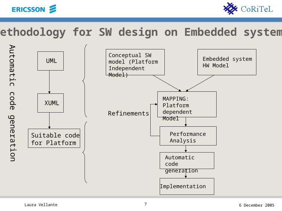
Conceptual SW model (Platform Independent Model)
Embedded system HW Model
MAPPING:Platform dependent Model
Automatic code generation
Implementation
Performance Analysis
UML
XUML
Suitable code for Platform
Au
tom
atic co
de
ge
nera
tion
Methodology for SW design on Embedded systems
Refinements

Laura Vellante 6 December 20058
Conceptual SW model (Platform Independent Model)
Embedded system HW Model
MAPPING
Automatic code generation
Implementation
UML
XUML
Suitable code for Platform
Au
tom
atic co
de
ge
nera
tion
Methodology for SW design on NP
Refinements
Performance Analysis
NP HW modeling is complex and long

Laura Vellante 6 December 20059
NP Activity main issues
CASE STUDY : SCTP on Freescale C5 SCTP in order to support IP signaling Protocol used in several nodes (core network, access, etc.)
Layer 4 protocol connection oriented
Protocol already implemented in Ericsson Node in order to have comparison w.r.t. implementation on existing nodes
ACTIVITY PHASES : Methodology development :
Research activity
Implementation activity

Laura Vellante 6 December 200510
Methodology development
1. Research activity on SW model based on Model Driven Based (MDB) approachCan be used also to other embedded system (e.g. FPGA)
2. Implementation activity in order to make experience on NP Platform
Two concurrent activities

Laura Vellante 6 December 200511
MDE FOR
NETWORK PROCESSORS
APPLICATIONS

Laura Vellante 6 December 200512
MDE : Motivations and ideas
“… “… Model Once, Generate Anywhere …”Model Once, Generate Anywhere …”
• Everything is a model– Design models instead of develop code.– Allowing to focus on problem specific issues rather than on
questions about its representation.
• Use models at different levels of abstraction– Integration is concerned on vertical level as well as on a horizontal
one.– Changes impacts are well localized during the whole process.

Laura Vellante 6 December 200513
What’s a model?
“… a model is an artefact that conforms to a meta-model and that represents a
given aspect of a system.…”
J.Bézivin 2004

Laura Vellante 6 December 200514
The Case Study
• Network Application :– STREAM TRANSMISSION
CONTROL PROTOCOL (SCTP)
SCTP Model
SCTP Implementation
Implementation
Conceptual SW Model
(PIM)
Embedded System Model

Laura Vellante 6 December 200515
… About the Domain…
• Different abstraction levels for the domain definition:– Generic Network Protocol. – 4th Layer Protocol.– 4th Layer Protocol Connection Oriented.
• Research activities in literature:– J.Pärssinen
• VTT Information Technology– Espoo, Finland
• 2000-2004
Laura Vellante 6 December 200516
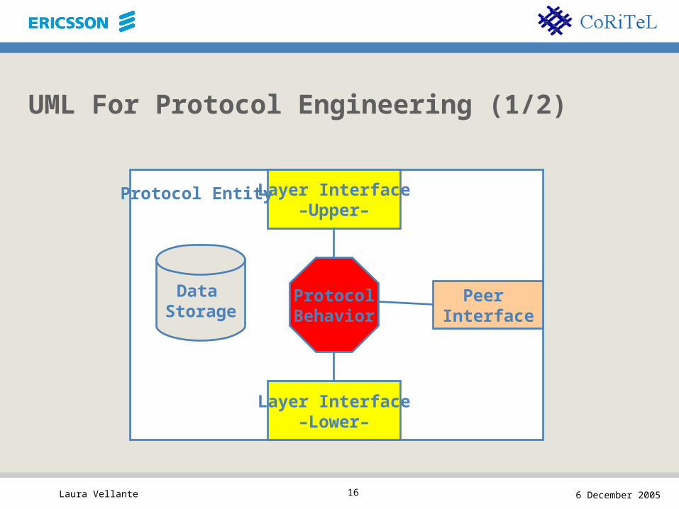
UML For Protocol Engineering (1/2)
Layer Interface–Upper–
Layer Interface–Lower–
Peer Interface
ProtocolBehavior
Data
Storage
Protocol Entity

Laura Vellante 6 December 200517
UML For Protocol Engineering (2/2)
• Protocol System Diagram– Names the protocol system, the system element instances it contains, and
creates associations between the system element instances. (Deployment Diagram)
• Protocol Interface Diagram– Specifies the sets of messages that can be sent and received between two
system elements, and it encapsulates these sets in one UML package. (Class Diagram)
• Protocol Entity Diagram– Defines the internal structure of a protocol entity. (Class Diagram)
• Behaviour Description Diagram – Describes the dynamic behaviour of the protocol entity. (State Diagram)

Laura Vellante 6 December 200518
Unified Modelling Language, UML
• UML is a language to analyse, to model, to specify, to visualize and to document a system project.
• UML isn’t a method, it doesn’t define a development UML isn’t a method, it doesn’t define a development processprocess
• It makes use of a series of diagrams

Laura Vellante 6 December 200519
Data Flow Diagrams, DFDs
• DFDs show the flow of data from external entities into the system, showed how the data moved from one process to another, as well as its logical storage.
• They are widely used in other fields (i.e. FPGA)• They assure not to lose any information, any data• They are not a development process.• They don’t show any control information or action, any
sequence of time

Laura Vellante 6 December 200520
DFDs & UML
• Their synergy seem to be very interesting to describe in a complete way the entire application (i.e. SCTP)
• DFDs allow to identify all the processes involved in the system (step1)
• UML allows to show control and temporal information (step2)

Laura Vellante 6 December 200521
Present Work
• Defining the network protocol model network protocol model (UML, DFD…)• Looking for the modeling approach (DFD, UML, and so
on), so to have a rigorous steps sequence to follow, and to be sure not to lose any element (data, functionalities…)
• Identifying the mapping subjectmapping subject, the “atomic functionatomic function”• Modeling SCTP by means of UML diagram, based on
Parssinen approach.

Laura Vellante 6 December 200522
Future Works and Open Issues
• Complete the model definition– static descriptions– dynamic descriptions
• Language Modelling (UML? Other languages?)• Working on the model transformations
– Choose an adequate target model– Specify the transformation rules– Implement a model-to-model transformation engine

Laura Vellante 6 December 200523
SCTP ON FREESCALE C5 NETWORK PROCESSOR

Laura Vellante 6 December 200524
FREESCALE C5e
• 16 channel processors grouped in 4 cluster (4 CP each)
• External memories (routing tables, packet to be processed)
Programming Language: C code and C-Ware Communication Programming Interfaces (C-Ware APIs), C libraries that provides to access to resources.
LEVEL 2 – LEVEL 3 APPLICATIONS

Laura Vellante 6 December 200525
NP and SCTP
Ethernet
SCTP
IPApplication designed for NP C5e (one cluster required)
Use of the code of a SCTP prototype library (sctplib)
How to map SCTP on the NP?How to map SCTP on the NP?

Laura Vellante 6 December 200526
Main Issues Related To The NP And SCTP
• Internal memories (DMEM e IMEM) limitations that impact on code development and data handling
• External memories handling
• SCTP code structures
• Data structures organization
• Packet & Chunk managing
• Lack of a clear and consistent documentation

Laura Vellante 6 December 200527
Instruction Memory Limitations
• Each CP has an internal 8 KByte IMEM• Each CP in a clustercluster shares an internal 32 KByte IMEM
CODE MAPPING ON THE NP

Laura Vellante 6 December 200528
Data Memory Limitations
• Each CP has an internal local 12kByte DMEM• Each CP in a cluster shares a local 48KByte DMEM
• It’s not possible to use the DMEM to storage large data (such the ones necessary for the associations management) and data that must be available for all CPs (because of the communication problems between CPs in different clusters.) It’s not possible to allocate DMEM in a dynamic way (i.e. doesn’t exist a malloc instruction)
• So the DMEM is used to storage only temporary data

Laura Vellante 6 December 200529
Data Structures Organization: What The NP Offers
• The TLU provides access to application-defined topology, control, and statistics tables in external SRAM.
• The BMU partitions the SDRAM into buffers. The BMU provides support for allocating and de-allocating buffers, reading from and writing buffers, and maintaining reference counts for multicast operations.
• The QMU manages all descriptor queues in SRAM and maintains per-queue status information.
Laura Vellante 6 December 200530
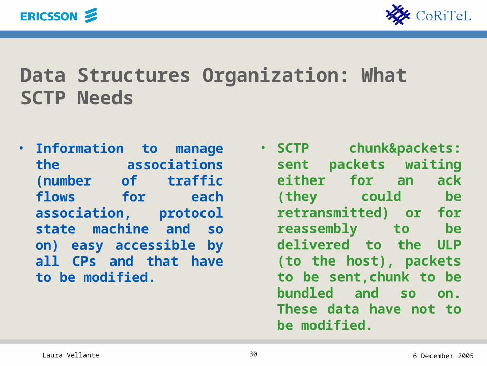
Data Structures Organization: What SCTP Needs
• Information to manage the associations (number of traffic flows for each association, protocol state machine and so on) easy accessible by all CPs and that have to be modified.
• SCTP chunk&packets: sent packets waiting either for an ack (they could be retransmitted) or for reassembly to be delivered to the ULP (to the host), packets to be sent,chunk to be bundled and so on. These data have not to be modified.

Laura Vellante 6 December 200531
SCTP Data On The NP
• Information to manage the associations
• SCTP packets
SRAM managed by TLU
SRAMs managed by BMU and QMU
Chunks&Packets
Chunks&Packets Descriptor

Laura Vellante 6 December 200532
SRAMs And Units Limits
• The SRAM are limited in size (!)• The units (TLU, BMU, QMU) are limited in number and kinds of
structures they can handle
The structures have to be arranged to fulfil both SCTP and NP requirements
This issue impacts on SCTP performance (i.e. maximum number of associations, maximum number of flows for association, and so on)

Laura Vellante 6 December 200533
SCTP On NP : Mapping
HOSTHOST NPNP

Laura Vellante 6 December 200534
SS
EE
NN
DD
HOSTHOST
RERE
CEI CEI
VEVE
SCTP On NP : Mapping

Laura Vellante 6 December 200535
SCTP On Clusters NP Mapping
• 1 Cluster for Ethernet/IP temination
• 2 clusters for SCTP (1 for sending operations and the other one for receive operations)
• 1 cluster is still not used
SEND FreeSEND RECEIVE Free
SCTP
Ethernet / IP

Laura Vellante 6 December 200536
SCTP Traffic Generator
• It doesn’t exist an SCTP traffic generator, we are developing it.
• The scope of the traffic generator is to validate the SCTP implementation (everything works right) and to do some performance evaluation.

Laura Vellante 6 December 200537
Performance Evaluation
• Performance evaluation means the valuation of the use of the NP in terms of memory occupation, execution time, number of memories access, number of read and write operations on external memories and so on.
It’s not possible to have system evaluationssystem evaluations in terms of delays, number of processed packets in a slot time and so on. They will be available at the end of the implementation!

Laura Vellante 6 December 200538
The methodology impact
• Mapping• Performance evaluation, in terms of both Network
Processor performance and system level performance
• Language code

Laura Vellante 6 December 200539
On Going & Future Works
• Implementing the receive function on the NP• Network Processor Performance Evaluation• SCTP Traffic Generator
• Realize an “SCTP peer” to communicate with the simulator, to simulate a whole SCTP data flow.

Laura Vellante 6 December 200540
Thank you for listening!
email: [email protected]
Thank you for listening!
email: [email protected]


![0. Cover [91484] 4/5/05 22:51 Page 2 - Laura Ashley …...Laura Ashley Holdings plcAnnual Report and Accounts 2005 Directors & Advisors Tan Sri Dr Khoo Kay Peng*+ Non-Executive Chairman](https://img.pdfslide.us/doc/110x75/5f2100b28e90ad1658597b54/0-cover-91484-4505-2251-page-2-laura-ashley-laura-ashley-holdings-plcannual.jpg)