Embed Size (px)
Citation preview

Lattice Design Optimization: Crowdsourcing Ideas in the Classroom
Dhruv Bhate The Polytechnic School, Arizona State University, Mesa, AZ 85284
Abstract
Crowdsourcing is a powerful method of generating ideas, particularly when there are many
possible solutions to a particular problem with no obvious process towards arriving at the optimum one. In this paper, results of a crowdsourcing exercise conducted in a 30-student classroom are reported. Students were tasked with using lattice design concepts to minimize the weight of a beam under bending, tension and torsion. Using the nTopology software, they approached the problem in three steps: (1) Selection/design of a unit cell, (2) Distribution of cell size, and (3) Optimization of the thickness of individual members. The first two steps were design decisions made by the students, the last step used nTopology's native solver. This work shares insights gained both in lattice design itself, as well as on the use of crowdsourcing in the classroom, particularly in the context of the rapidly evolving field of Design for Additive Manufacturing.
Introduction
Design for Additive Manufacturing (DFAM) is a popular subject being taught at several
universities including the Arizona State University (ASU), where it was offered for the first time in the spring semester in 2018 (January–May). The DFAM course has a special section towards the end of the course on cellular materials, and a key part of that section is the use of design tools to generate structures with these materials. For this first offering, 30 students enrolled in the course and used a non-commercial, beta version of nTopology’s Element version 1.20 software [1], with the ability to conduct analysis and parameter optimization. nTopology’s Element is a “nTopology's Element is a generative, function-based engineering application at the intersection of CAD, simulation, and industrial manufacturing,” to quote the company’s website. In particular, nTopology has established a presence in the AM design community for their ability to rapidly generate lattice structures in 3D objects with a range of user options and an easy-to-use user interface.
Cellular materials in AM is a relatively immature, but rapidly evolving space. Most
commercial design tools have only recently begun to incorporate design capabilities for these structures, especially with analysis and optimization capability. Thus, there are more questions to be asked than answers available. It was in this context that students were tasked with finding the answers to design questions that while simple on the surface, do not have ready answers to them. They were asked to use nTopology Element to explore the design space and in so doing, help the entire class identify possible solutions to the questions posed. This paper describes this process, the findings and conclusions from this exercise. It begins by identifying four key questions in the design process. Three of these questions were then posed to the students in the form of a project, which is then described. Findings from students work is then reported, followed by conclusions drawn not just about the exercise of using a classroom setting for generating design ideas, but also about the very nature of cellular material design optimization itself. But first, we begin with a discussion of what the key questions in cellular design even are, to set the stage for the project to follow.
32
Solid Freeform Fabrication 2018: Proceedings of the 29th Annual InternationalSolid Freeform Fabrication Symposium – An Additive Manufacturing Conference
Reviewed Paper

Background: The Four Questions of Cellular Material Design
From a practical standpoint, when it comes to incorporating cellular material designs into structures, there are four main questions that the designer needs to address:
• What specific unit cell(s) should be selected? • How best should the size of the cells vary spatially? • How best should the cell parameters be optimized? • How best should these cells be integrated with the larger form of the structure?
Each of these is discussed below in more detail. 1. Unit Cell(s) Selection
A designer can select from, quite literally, an infinitely large list of unit cells. Indeed, a
designer could even construct a cell with basic elements such as a beam or a face, instead of selecting from an available library. There are different ways to classify cellular materials, but it helps to think of cellular materials at the following four levels (inspired by nTopology [1]):
1. Dimensionality: Whether the cells occupy a volume or a surface 2. Tessellation: The compartmentalization of space into independent volumes of a certain
shape 3. Elements: The use of beams and/or shells/faces within the tessellated space 4. Connectivity: The actual arrangement of the elements within the tessellated space
Thus, a hexagonal honeycomb, for example, has volumetric dimensionality with a
hexagonal prism tessellation with shell elements arranged along the prism edge-walls. Other examples are shown in Figure 1 to demonstrate the range of these four levels.
Figure 1. A selection of cell shapes with a 4-level classification scheme inspired by nTopology's "Rule
Builder" [1]
2. Cell Size Distribution Once a cell shape has been selected, the larger structure needs to be populated with these
cells. The main concern then is one of size, and its distribution, which may be termed Cell Size
33
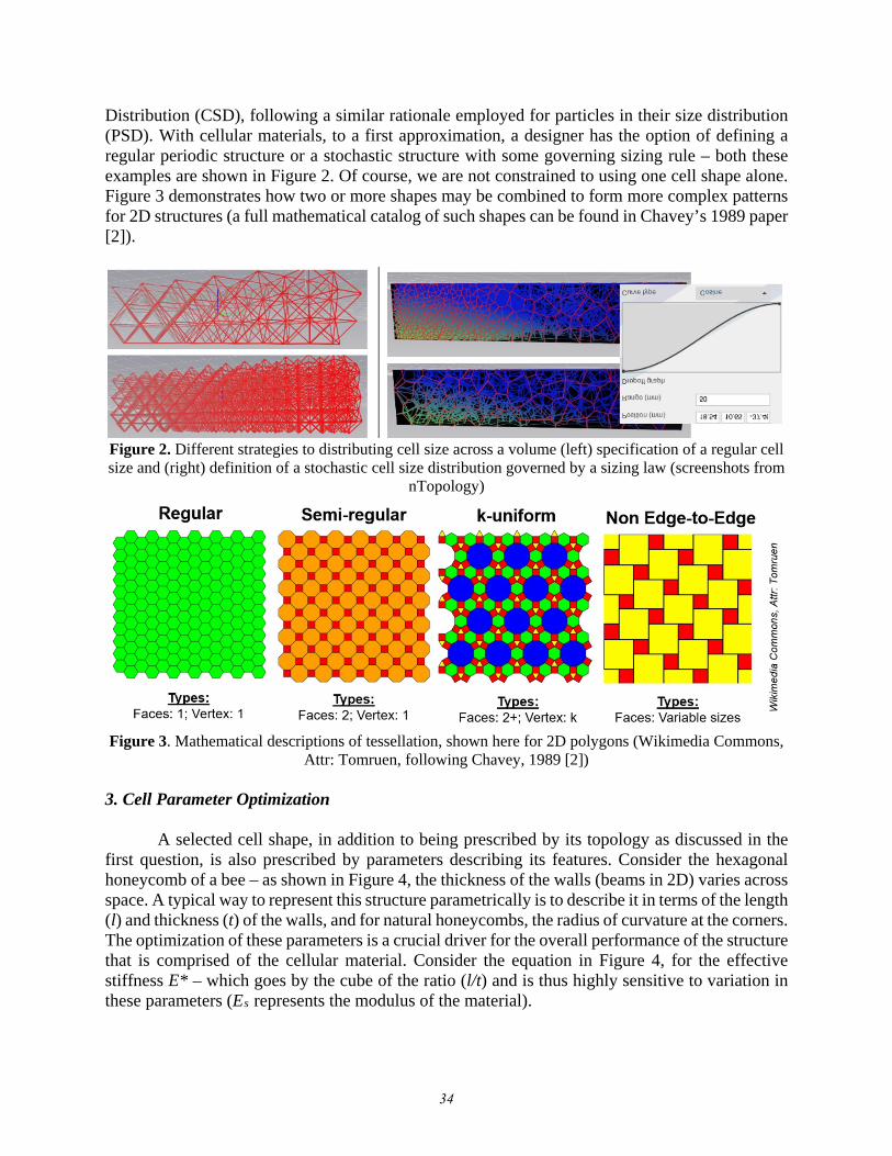
Distribution (CSD), following a similar rationale employed for particles in their size distribution (PSD). With cellular materials, to a first approximation, a designer has the option of defining a regular periodic structure or a stochastic structure with some governing sizing rule – both these examples are shown in Figure 2. Of course, we are not constrained to using one cell shape alone. Figure 3 demonstrates how two or more shapes may be combined to form more complex patterns for 2D structures (a full mathematical catalog of such shapes can be found in Chavey’s 1989 paper [2]).
Figure 2. Different strategies to distributing cell size across a volume (left) specification of a regular cell size and (right) definition of a stochastic cell size distribution governed by a sizing law (screenshots from
nTopology)
Figure 3. Mathematical descriptions of tessellation, shown here for 2D polygons (Wikimedia Commons,
Attr: Tomruen, following Chavey, 1989 [2]) 3. Cell Parameter Optimization
A selected cell shape, in addition to being prescribed by its topology as discussed in the
first question, is also prescribed by parameters describing its features. Consider the hexagonal honeycomb of a bee – as shown in Figure 4, the thickness of the walls (beams in 2D) varies across space. A typical way to represent this structure parametrically is to describe it in terms of the length (l) and thickness (t) of the walls, and for natural honeycombs, the radius of curvature at the corners. The optimization of these parameters is a crucial driver for the overall performance of the structure that is comprised of the cellular material. Consider the equation in Figure 4, for the effective stiffness E* – which goes by the cube of the ratio (l/t) and is thus highly sensitive to variation in these parameters (Es represents the modulus of the material).
34

Figure 4. The hexagonal honeycomb can be described in terms of the lengths of its walls, their
thicknesses and further, the radius at the corner
nTopology permits modification of thickness parameters in three different ways: (1) as a stipulated value applied globally, or (2) one varying spatially per a prescribed function (modifier), or (3) the solver locally optimizes the thickness of cells in response to a global load case (see Figure 5: left, middle and right, respectively). This is a crucial aspect of optimizing with cellular materials, something which exploits Additive Manufacturing's capability to attain local tunability of structure and is difficult to achieve otherwise.
Figure 5. Three methods of prescribing cell thickness - (left) global prescription of a thickness value, (middle) thickness specified in terms of a function and (right) thickness optimized by the solver in
response to local stresses (Screen captures from nTopology) 4. Integration
A crucial question is how one should integrate these cellular materials into the actual engineering structure and its adjacent parts in an assembly where one or more components contain cellular materials. One key aspect of integration involves termination of cells at skin boundaries. This is relatively straightforward when bridging between two surfaces with conformal lattices, but more challenging in complex structures such as the one shown in Figure 6. How thick should the skin be? What is the best way to blend lattices with the skin? Are there regions that don’t need a skin or a sharp boundary (for bone integration in implants, for example)? While software have capabilities to enable this computationally, it is not always clear what is the best solution from a part performance and manufacturability standpoint.
With this background in mind, a project was designed to have students explore in the classroom the first three of the four questions posed above. To keep the project manageable, the fourth question (of integration) was excluded from the project – students were essentially asked to replace a homogenous solid structure with a cellular one and not to concern themselves with an outer skin or retaining mating surfaces.
35

Figure 6. Infilling a geometry with a lattice material raises questions around how to terminate these
structures at the boundary of a structure (Screen captures from nTopology)
Project Description Students were given a simple square beam design of length 5 inches and a 1 inch x 1inch cross-section. The beam had material properties derived from a datasheet for Nylon 12 using the Selective Laser Sintering process as follows:
o Young’s Modulus = 1650 MPa o Shear Modulus = 594 MPa o Yield Stress = 42 MPa
Students were also given a minimum feature diameter of 1mm to represent a manufacturing
constraint. Three load cases were assigned, each using a distributed load for consistency and to study local effects. The three load cases approximated bending, torsion and tension on one end, with the other end fixed. These cases were selected to simplify the analysis to something manageable on students’ own computers and also to allow for, in principle at least, a deeper understanding of the connection between design choice and response.
• Case I: Cantilever bending: All degrees of freedom fixed at one square face, a 250 N distributed bending load applied at an edge on the opposite face as shown in figure 7
Figure 7. Case I: cantilever beam under bending, applied as a distributed edge load
36

• Case II: Cantilever Beam Torsion: To simplify this within available load options, this
was simplified as distributed edge shear loads. All degrees of freedom were fixed at one square face, a distributed shear load of 1000 N applied at each edge in directions as shown in Figure 8.
Figure 8. Case II: cantilever beam under simulated torsion, applied as a shear load on 4 edges (nTopology did not support torsional moments at the time of use)
• Case III: Cantilever Tension: All degrees of freedom fixed at one square face, a 150 N
distributed load applied at EACH edge on the opposite face as shown in figure 9.
Figure 9. Case III: cantilever beam under tension, also applied on 4 edges as distributed loads
Students were then asked to develop a solution that met the following constraints: - Meets all the specified requirements while keeping Von Mises stress below the yield stress - Generate a part that is printable with the manufacturing constraint specified - Minimize the volume of the final part (volume considered equivalent to mass for the
purposes of the project)
Students received 30 points in total for all load cases for correct and complete submissions (10 points for each load case), and another 30 points assigned according to a competitive evaluation where the student with the lowest volume for a correct submission for a specific load case received 30 points, the next 29 and so on – averages of all 3 load cases were added to the initial 30, making this project worth 60 points in all. This was done to incentivize the students to pursue ideas that
37

would further reduce volume relative to their peers. The students were given two weeks to complete this project, and all had access to install nTopology on a computer of their choosing.
Results
Of 30 students, 26 provided complete submissions with all 3 cases and qualified for the
competition. Using the aforementioned scoring method, the class average came to 40.6. Below is the distribution of volumes for the 26 complete submissions, for each case. The initial volume of the beam was 5 cubic inches, or 81,935 mm3. Final volumes attained by the 26 students with complete submissions are plotted in Figure 10. A significant peak at the bottom end suggest students were moving in the direction with significant reductions in volume attained. The initial beam design and loading conditions were arbitrarily selected to ensure a reasonable solution, so the magnitude of reduction itself is not significant for the purposes of this discussion.
Figure 10. A summary of final volumes for all students that submitted correct solutions, against an initial volume of 81,935.3 (all units in mm3)
In the following discussion, the top 3 results for each load case are presented, along with
observations made specific to the strategies that the students employed that may serve as useful indicators for lattice design. Overarching conclusions are drawn in a following section.
38

Case I: Bending 1. Ladder truss (6016.58 mm3): The student with the lowest volume was inspired by long
stretch ladder structures. While this is more like a truss structure in architecture, it works at smaller scales too and is a good reminder not to assume a cellular material design is going to be the best, especially when the loading conditions are simple.
Figure 11. Ladder truss like structure – applying a global design solution and not necessarily thinking in
terms of infilling
2. Hexagonal Prismatic Lattice (6232 mm3): The hexagonal prismatic lattice seemed to work well – two students used this and got top 5 results. This may have something to do with the fact that in bending the top and bottom fibers of the beam are either in tension or compression. Honeycombs oriented along the fibers are probably bending and deforming freely, not building up internal stresses.
Figure 12. Using in-plane deformation of hexagonal honeycomb structures (pone to bending) to minimize
stress build-up
3. Stochastic Lattice (6375.58 mm3): The stochastic lattice came in third. The student evaluated a range of density distributions in ending up with this solution.
Figure 13. Stochastic lattice with a higher density at one end with higher stresses
39

Case II: (Simulated) Torsion 1. Localization (6073.79 mm3): The best result in class essentially realized that most of the
action is at the end, and the rest of the model was just connecting to the fixed boundary. A key strategy here is that we need not populate an entire structure with cellular materials and can localize it as needed.
Figure 14. Localization of lattice structures at the place of shear load application
2. Localization (6169.15 mm3): Similar idea as above, but a different strategy from a design
standpoint where these beams were added at the last group of cells only. Deleting some of the unstressed beams in the interior may have made this the lowest volume and further driven down volume.
Figure 15. Another localization strategy with a vertex centroid cubic truss structure
3. Stochastic Lattice (7976.8 and 8008.7 mm3): Stochastic lattices as a general rule seem good
strategies, ending up in the top 5 results provided by students.
Figure 16. Stochastic lattices with thickening at the location of load application
40

Case III: Tension
1. Frame design (2312-2475 mm3): Four students came up with a similar design concept shown below and got the lowest volume in class, two more had similar designs with additional lattice trusses connecting the frame together. To some students this was intuitive, others arrived at it by removing beams and realized the only load transfer was axial. Sometimes simplicity is the best, even in cellular material design and it is good to step back and think through the problem before playing with the software. While this is technically a truss-design, not a cellular material, but is a good reminder to students that it may not make sense to do cellular materials for every environment.
Figure 17. Examples of a frame structure with no infill resulting in the lowest volume solutions
2. Stochastic Lattice (5563.5 mm3): The first cellular material structure that had the lowest
volume used stochastic lattices. Arguably further reduction would have been possible with beam deletion or a different modifier, suggesting again that stochastic lattices may be a good general purpose strategy.
Figure 18. Stochastic lattices perform reasonably well under simple loading conditions such as uniaxial
tension, but add significant volume over a simple frame structure
41

Discussion
The main objective of this work was to assess if the classroom could be used to simultaneously instruct and generate new knowledge. The results were mixed. With regard to instruction, the results were positive, as measured from the students rating of the course as a whole (averaging 4.61/5 from 16 responses). In addition, students’ (anonymous) responses to the question “What did you like most about this course?” included these responses relevant to this work:
• “Learning different technologies and simulation software” • “The introduction into the Additive Manufacturing world and the different software
learned throughout the course” • “Fun to explore concepts like lattice generation and Topology optimization, as well as
learning by doing both of these things” • “Learning software and optimization tools that will be useful in industry” • “It gave me exposure to multiple software: ANSYS and nTopology”
On the flip side, in response to the question “What did you like least about this course?”,
two students did provide input relevant to the project discussed here:
• “Some of the experimental software was a little bit buggy” • “As the course was a pilot course, many assignments and projects were ill-defined and
took an exceptionally long amount of time and resources to complete. Many times the software and tools provided in class proved insufficient for these assignments.”
The above inputs were not cherry-picked or edited, they are consistent with feedback delivered
verbally to the instructor. It can be stated with some certainty therefore that the instructional value of the project and the use of the software in the classroom towards a project was value-added to the students.
With regard to new knowledge generated, the results are mixed. On the positive side, the
project allowed for an articulation about the four key questions in cellular material design, as discussed in this paper, which to the best of our knowledge is the first concise exploration of these themes in the context of the use of commercial cellular material design software. On the other hand, no clear design guidelines emerged from this work but this can be attributed to the exploratory nature of the effort and the fact that this was the first use of any cellular material design optimization software by the instructor and students alike. Therefore it is not clear if students that randomly selected shapes did better than those that applied a strong rationale. Some broad technical insights that did emerge from this study are:
• Cellular materials are not always an optimal strategy from a purely structural standpoint
– this is especially true in simple uniaxial loading conditions. • Localization of infill is a key decision prior to the selection of a cellular material –
today’s approaches tend to assume complete infilling. This can be achieved by beam deletion in unstressed areas but requires an iterative approach at the present moment.
• Stochastic cellular materials hold great promise primarily on account of their relative ease of spatial manipulation by specifying modifiers and changing local densities.
42

Improvements Based on the findings of this work, the use of projects to meet the dual objectives of
instruction and knowledge creation are feasible. Some learnings for future offerings to improve the quality of the generated knowledge are:
• Frame the optimization question in more direct terms that have established baselines, such as geometric efficiency [3] or classical cellular material parameters such as specific modulus [4].
• Reduction in scope to enable qualitative comparisons to try and identify trends for design variables such as cell shape, size distribution and parametrization that were covered in the first 3 questions discussed previously.
• Incentivizing student work beyond just grades, but with an opportunity to present or publish work may lead to deeper discussions than simply generating results with software and reporting them in a document, which was the format used here.
Acknowledgements
The author would like to thank nTopology, Inc. for their supporting us at Arizona State
University by providing beta versions of the full version of nTopology to all 30 students. The author also acknowledges all 30 students in my Spring 2018 EGR 598 (Design for Additive Manufacturing) course at Arizona State University – it is their work that I am summarizing in this paper.
References [1] NTopology, “Element.” 2018. [2] D. Chavey, “Tilings by Regular Polygons - II A Catalog of Tilings,” Comput. Math.
Applic., vol. 17, no. 1–3, pp. 147–165, 1989. [3] J. B. Berger, H. N. G. Wadley, and R. M. McMeeking, “Mechanical metamaterials at the
theoretical limit of isotropic elastic stiffness,” Nature, vol. 543, no. 7646, pp. 533–537, 2017.
[4] M. . Ashby, “The properties of foams and lattices,” Philos. Trans. R. Soc. A Math. Phys. Eng. Sci., vol. 364, no. 1838, pp. 15–30, 2006.
43