Embed Size (px)
Citation preview

© Finisar Corporation 1
IX Fórum 9 December 8, 2015 Christian Urricariet
Latest Trends in Data Center Optics

© Finisar Corporation 2
Optics industry leader with $1B+ annual revenue
Founded in 1988
IPO in 1999 (NASDAQ: FNSR)
27% worldwide transceiver market share (2014)
Best-in-class broad product line
Vertically integrated with low cost manufacturing
Significant focus on R&D and capacity expansion
Experienced management team
14,000 employees
1300+ Issued U.S. patents
Technology Innovator. Broad Product Portfolio. Trusted Partner.
Finisar Corporation
Corporate Headquarters: Sunnyvale, CA USA
© Finisar Corporation 3
Broad Product Portfolio and Customer Base
SFP+ SFP
X2/XENPAK
XFP
PRODUCTS CUSTOMERS
ROADM line card
Tunable laser
Active Optical Cables
QSFP/QSFP28
CXP Optical Engine (BOA)
SFP
PON
WSS
XFP
DATACOM
TELECOM
CUSTOMERS PRODUCTS
CFP2/ CFP4
SFP+
CATV
WDM Passives
Coherent Transponder
High speed components
Amplifiers
CFP
CFP2-ACO

© Finisar Corporation 4
Data Center connections are moving from 10G/40G, to 25G/100G
Within the Data Center Rack 10GE being deployed now 25GE to be deployed soon 50GE to the server will follow
Between Data Center Racks 40GE being deployed now 100GE to be deployed soon What follows? 200GE or 400GE?
Long Spans/Inter-Data Centers & WAN
100GE being deployed until now 400GE being standardized now What follows? 800GE, 1TE or 1.6TE?
Building 1
Building 2 / WAN
10G Intra-rack 10/40G Inter-rack 40/100G Long span/Inter-buildings
Data Center Connections are Changing

© Finisar Corporation 5
New Architectures in Hyperscale Data Centers Most large data center networks are architected on a 3-tier topology Cloud data center networks are migrating from traditional 3-tier to flattened 2-tier topology
Hyperscale Data Centers becoming larger, more modular, more homogenous Workloads spread across 10s, 100s, sometimes 1000s of VMs and hosts Higher degree of east-west traffic across network (server to server)
Access Layer (Switches)
Aggregation Layer
(Switches)
Core Layer (Routers)
Traditional ‘3-tier’ Tree Network
Nor
th-S
outh
Servers and Compute (w/ NICs)
New ‘2-tier’ Leaf-Spine Network
East-West
Servers and Compute (w/ NICs)

© Finisar Corporation 6
The Hyperscale/Cloud Data Center
The RACK is the minimum building block. The goal is to connect as many racks
together as possible. Heavy ‘East-West’ traffic
(server to server). Minimum over-subscription. Each leaf switch fans out to all
spine switches (high radix).
TOR Switch
Leaf Switch
Spine Switch
Servers
RACK
Core/L3 Switch

© Finisar Corporation 7
Connections in the Hyperscale/Cloud Data Center
TOR Switch
Leaf Switch
Spine Switch
Core/L3 Switch
Servers
RACK
TOR Switch to Server links: Deploying mostly 10GE SR/DAC today. Will deploy 25GE SR/AOC soon. Roadmap is 50GE SR/AOC next.
Leaf Switch to TOR Switch links: Deploying mostly 40GE SR4 today. Will deploy 100GE SR4/AOC soon. Roadmap may be 200GE SR next.
Spine Switch to Leaf Switch links: Deploying mostly 40GE SR4/LR4 today. Will deploy 100GE SR4/CWDM4 soon. Roadmap may be 200GE SR/LR next.
Core Switch/Router to Spine Switch: Deploying mostly 40GE LR4 today. Will deploy 100GE CWDM4/LR4 soon. Roadmap is 200GE or 400GE next.

© Finisar Corporation 8
Interconnect Trends in the Data Center Market
Significant increase in 100G and 25G port density

© Finisar Corporation 9
Interconnect Trends in the Data Center Market
Significant increase in 100G and 25G port density
Smaller form factors, e.g., QSFP28 modules
Power dissipation <3.5W
Active Optical Cables
On-board optics for very high port density

© Finisar Corporation 10
time
CFP 4 ports/chassis
24W
CFP2 8-10 ports/chassis
8W
CFP4 16-18 ports/chassis
5W
Deployments until today
QSFP28 18-20 ports/chassis
3.5W
100G Optical Module Form Factor Evolution

© Finisar Corporation 11
100GE optical transceivers QSFP28 is standardized by SFF-8665 (SFF Committee) It has a 4-lane, retimed 25G I/O electrical interface (CAUI-4) Supports up to 3.5W power dissipation with standard cooling Also used for 4x 25GE applications
100GE active optical cables (no optical connector)
QSFP28 is the 100GE module form factor of
choice for new data center switches
100G QSFP28 Module

© Finisar Corporation 12
QSFP28: 100G and High-Density 25G
QSFP28 QSFP28
SFP28
SFP28
SFP28
SFP28
4x25G Breakout
QSFP28 QSFP28 QSFP28 QSFP28
Point-to-Point 100G QSFP28 QSFP28
QSFP28 QSFP28
QSFP28 QSFP28
QSFP28 QSFP28
QSFP28 QSFP28
QSFP28 QSFP28
QSFP28 QSFP28
QSFP28 QSFP28
4x25G Shuffle
QSFP28 = Quad SFP28 QSFP28 is both a 100G and a high-density 25G form factor
QSFP28 QSFP28 QSFP28 QSFP28
SFP28
SFP28
SFP28
SFP28 QSFP28 QSFP28
QSFP28 QSFP28
SFP28
SFP28
SFP28
SFP28
General Case: Breakout and Shuffle
QSFP28 will have very high volumes, because it supports both 100G and
25G links.

© Finisar Corporation 13
25GE optical transceivers SFP28 is standardized by the SFF Committee It has a 1-lane, retimed 25G I/O electrical interface Supports up to 1W power dissipation with standard cooling Used for 25GE ports in server and switches
25GE active optical cables
25G SFP28 Module
SFP28 is the 25GE module form factor of choice for
new Servers / NICs

© Finisar Corporation 14
These optics are not pluggable; they are mounted on the host PCB Used today on core routers, supercomputers and some switches Very short host PCB traces enable low power dissipation Higher bandwidth density can be achieved by:
More channels: Up to 12+12 Tx/Rx, or 24Tx and 24Rx Higher data rate per channel: 10G/ch and 25G/ch variants today, 50G/ch in the future
Board-Mounted Optical Assembly (BOA)

© Finisar Corporation 15
Interconnect Trends in the Data Center Market
Significant increase in 100G and 25G port density
Extension of optical links beyond the Standards

© Finisar Corporation 16
Duplex and parallel optics products continue to proliferate This results in a proliferation of standards, de facto standards, MSAs, and
proprietary codes, each optimized for a particular use case
SR, USR, LR, LR Lite, LRM, ER, ZR, LX4, PR, 8xFC SMF, 8xFC MMF, SAS3, PCIe3, OTU2
10 Gb/s
SR4 (100m), 4xSR Lite (100m), eSR4 (300m), 4xSR, LR4, 4xLR, 4xLR Lite, ER4, LM4, LM4 Univ, 4xQDR, 4xFDR, 4x16GFC SMF, 4x16GFC MMF, 4xSAS3, 4xPCIe3, OTU3, OTU3e2, SWDM4
40-56 Gb/s
SR4, SR10, 10x10GSR, 12x10GSR, LR4, 10x10GLR, 4xEDR, ER4, ER4f, 4x32GFC, OTU4, PSM4, CLR4, CWDM4, SWDM4
100-128 Gb/s
Optical Standards Proliferation

© Finisar Corporation 17
Parallel (MPO) Duplex (LC) M
ultim
ode
Sing
le M
ode
40G Ethernet QSFP+ Modules
Multimode distances refer to OM3/OM4 Single mode distances refer to SMF28
Parallel links can be broken out to 4 separate 10G connections
Black = Standardized interfaces
Blue = MSA/Proprietary interfaces
4xLR • 10km
4xLR Lite • 2km
LR4 • 10km ER4 • 40km
SR4 • 100/150m
eSR4 & 4xSR • 300/400m
Duplex WDM cannot be broken out to separate 10G connections
A duplex multimode product is required to re-use the same fiber plant used for 10GE
LM4 • 140/160m/1km

© Finisar Corporation 18
Parallel (MPO) Duplex (LC) M
ultim
ode
Sing
le M
ode
100G Ethernet QSFP28 Modules
Multimode distances refer to OM3/OM4 Single mode distances refer to SMF28
Parallel links can be broken out to 4 separate 10G connections
Black = Standardized interfaces
Blue = MSA/Proprietary interfaces
PSM4 • 500m
LR4 • 10km CWDM4/CLR4 • 2km
SR4 & 4x25G-SR • 70/100m
SR4 without FEC • 30/40m
Duplex WDM cannot be broken out to separate 10G connections
A duplex multimode product is required to re-use the same fiber plant used for 10GE

© Finisar Corporation 19
Various recent 25G and 100G Ethernet standards and MSAs require the use of RS-FEC (aka, “KR4 FEC”) on the host to increase overall link length:
RS-FEC does not increase the total bit rate, but it introduces an additional latency of ~100ns in the link. Some applications like HFT have little tolerance for latency.
The fiber propagation time of each bit over 100m of MMF is ~500ns The amount of additional latency introduced by RS-FEC may be significant for the overall performance of short links <100 meters (see next page).
But the fiber propagation time of each bit over 500m of SMF is ~2500ns The amount of latency introduced by RS-FEC is not significant for the overall performance of links >500 meters.
Impact of Latency on 25G/100G Ethernet Optical Links
Standard Link Length with RS-FEC
IEEE 802.3bm 100GBASE-SR4 100m on OM4 MMF
IEEE P802.3by 25GBASE-SR 100m on OM4 MMF
100G CWDM4 MSA 2km on SMF
100G PSM4 MSA 500m on SMF

© Finisar Corporation 20
• Support of 25G/100G Ethernet links without FEC Lower latency Lower host power dissipation
• Standard QSFP28 and SFP28 form factors • Supports 4:1 fan-out configuration • Up to 30 meters on OM3 / 40 meters on OM4 MMF
QSFP QSFP28
SFP28
SFP28
SFP28
SFP28
Low-Latency QSFP28 SR4 and SFP28 SR without FEC

© Finisar Corporation 21
Interconnect Trends in the Data Center Market
Significant increase in 100G and 25G port density
Extension of optical links beyond the Standards
Reutilization of existing 10G fiber plant on 40G and 100G

© Finisar Corporation 22
Why Duplex Multimode Fiber Matters
Data centers today are architected around 10G Ethernet Primarily focused on 10GBASE-SR using duplex MMF (LC) Data center operators are migrating from 10G to 40G or
100G, but want to maintain their existing fiber infrastructure SR4 requires ribbon multimode fiber with an MPO connector
• Not provided by pre-installed fiber plant LR4 requires single mode fiber
• Not provided by pre-installed fiber plant
Data centers want to upgrade from 10G to 40 and 100G without touching the duplex MMF fiber infrastructure

© Finisar Corporation 23
Industry group to promote SWDM technology for duplex MMF in data centers.
SWDM uses 4 different wavelengths in the 850nm region, where MMF is optimized, which are optically multiplexed inside the transceiver.
SWDM enables the transmission of 40G (4x10G) and 100G (4x25G) over existing duplex multimode fiber, using LC connectors.
Finisar is a founding member of the SWDM Alliance.
More information at www.swdm.org

© Finisar Corporation 24
Parallel (MPO) Duplex (LC) M
ultim
ode
Sing
le M
ode
40G Ethernet QSFP+ Modules
Multimode distances refer to OM3/OM4 Single mode distances refer to SMF28
Parallel links can be broken out to 4 separate 10G connections
Black = Standardized interfaces
Blue = MSA/Proprietary interfaces
4xLR • 10km
4xLR Lite • 2km
LR4 • 10km ER4 • 40km
SR4 • 100/150m
eSR4 & 4xSR • 300/400m
Duplex WDM cannot be broken out to separate 10G connections
Bi-directional • Limited use
SWDM4 • Being tested
LM4 • 140/160m/1km

© Finisar Corporation 25
Parallel (MPO) Duplex (LC) M
ultim
ode
Sing
le M
ode
100G Ethernet QSFP28 Modules
Multimode distances refer to OM3/OM4 Single mode distances refer to SMF28
Parallel links can be broken out to 4 separate 10G connections
Black = Standardized interfaces
Blue = MSA/Proprietary interfaces
PSM4 • 500m
LR4 • 10km CWDM4/CLR4 • 2km
SR4 & 4x25G-SR • 70/100m
SR4 without FEC • 30/40m
Duplex WDM cannot be broken out to separate 10G connections
SWDM4 • Being tested

© Finisar Corporation 26
Interconnect Trends in the Data Center Market
Significant increase in 100G and 25G port density
Extension of optical links beyond the Standards
Reutilization of existing 10G fiber plant on 40G and 100G
Moving beyond 100G, to 200G and 400G!

© Finisar Corporation 27
Service Provider Applications: 400GE Router-Router and Router-Transport client interfaces Critical requirements are time to market and supporting multiple reaches. Currently deploying tens of thousands of 100GE CFP/CFP2/CFP4. First generation 400GE client module will need to provide a port density advantage
with respect to using 4x QSFP28.
Data Center and Enterprise:
200GE uplinks and 4x100GE fan-outs Critical requirement is high port count/density. Currently planning on deploying 25G SFP28 on the server and 100G QSFP28 on
switches starting in CY2016. A 400G “QSFP112” module will take several years to be feasible due to power
dissipation and size limitations. A better product for the switch may be a 200GE QSFP56 module that could also
support 4x50GE fan-out. Servers have a roadmap to 50GE I/O already.
Distinct 200G/400G Applications in the Market
© Finisar Corporation 28
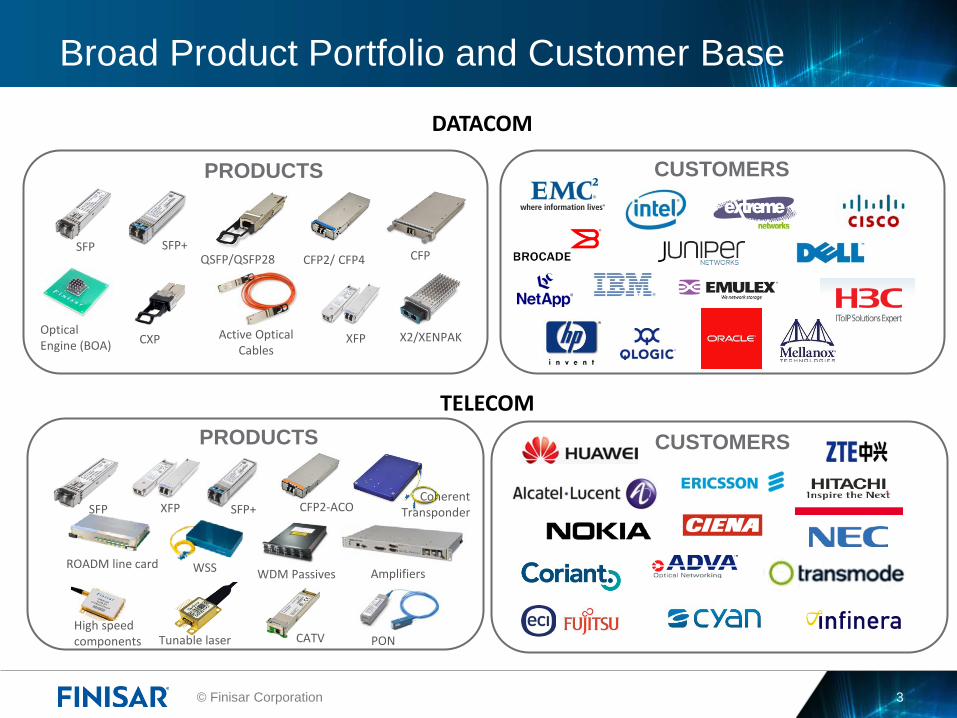
200GE and 400GE Standardization
The 400GE Standard is already being defined in IEEE P802.3bs
Standard is expected to be ratified in December 2017 Link objectives: 400GBASE-SR16 100m on parallel MMF
400GBASE-DR4 500m on parallel SMF 400GBASE-FR8 2km on duplex SMF 400GBASE-LR8 10km on duplex SMF
Electrical I/O: CDAUI-8 8x50G PAM-4 CDAUI-16 16x25G NRZ
Optical I/O: SR16 will be based on 16x25G NRZ LR8 & FR8 will be based on 8x50G LAN-WDM PAM-4 DR4 will be based on 4x100G PSM PAM-4
50G and 200G Ethernet standardization is now being studied by IEEE
Optics suppliers are already working on components to support these new rates Based on VCSELs, DFB laser and SiP technologies ICs and test platforms that support PAM-4 encoding

© Finisar Corporation 29
400GE CFP8 Optical Transceiver Module
CFP8 module dimensions are similar to CFP2. Enables 6.4 Tb/s per host board (8x2 modules in a 1RU configuration).
Supported ports: 16x400G, 64x100G, 128x50G, 256x25G
Supports standard IEEE 400G multimode and single mode interfaces Supports either CDAUI-16 (16x25G) or CDAUI-8 (8x50G) electrical I/O. It is being standardized by the CFP MSA

© Finisar Corporation 30
Summary
Large growth in web content and applications is driving: Growth in bandwidth and changes in data center architectures Subsequent growth in number of optical links Large increase in power requirements
25G, 40G and 100G optics support this growth today with: Smaller module form factors for higher port density Lower power consumption and cost per bit Increased performance to leverage existing infrastructure
New Ethernet speeds are being standardized: 50G, 200G, 400G
Questions?
Contact Us E-mail: [email protected] www.finisar.com

© Finisar Corporation 31
Thank You