Embed Size (px)
Citation preview

www.bookspar.com | VTU NEWS | VTU NOTES | QUESTION PAPERS | FORUMS | RESULTS
www.bookspar.com | VTU NEWS | VTU NOTES | QUESTION PAPERS | FORUMS | RESULTS
LATERAL EARTH PRESSURE
INTRODUCTION
Soil is neither a solid nor a liquid, but it exhibits some of the characteristics of both. One of the characteristics similar to that of a liquid is its tendency to exert a lateral pressure against any object in contact. This important property influences the design of retaining walls, abutments, bulkheads, sheet pile walls, basement walls and underground conduits which retain or support soil, and, as such, is of very great significance. Retaining walls are constructed in various fields of civil engineering, such as hydraulics and irrigation structures, highways, railways, tunnels, mining and military engineering.
LATERAL EARTH PRESSURES
Lateral earth pressure is the force exerted by the soil mass upon an earth-retaining structure, such as a retaining wall.
There are two distinct kinds of lateral earth pressure; the nature of each is to be clearly understood. First, let us consider a retaining wall which holds back a mass of soil. The soil exerts a push against the wall by virtue of its tendency to slip laterally and seek its natural slope or angle of repose, thus making the wall to move slightly away from the backfilled soil mass. This kind of pressure is known as the ‘active’ earth pressure of the soil. The soil, being the actuating element, is considered to be active and hence the name active earth pressure. Next, let us imagine that in some manner the retaining wall is caused to move toward the soil. In such a case the retaining wall or the earth-retaining structure is the actuating element and the soil provides the resistance which soil develops in response to movement of the structure toward it is called the ‘passive earth pressure’, or more appropriately ‘passive earth resistance’ which may be very much greater than the active earth pressure. The surface over which the sheared-off soil wedge tends to slide is referred to as the surface of ‘sliding’ or ‘rupture’.
Active pressures are accompanied by movements directed away from the soil, and passive resistances are accompanied by movements towards the soil. Logically, therefore, there must be a situation intermediate between the two when the retaining structure is perfectly stationary and does not move in either direction. The pressure which develops in this condition is called ‘earth pressure at rest’. Its value is a little larger than the limiting value of active pressure, but is considerably less than the maximum passive resistance. This is indicated in Fig

www.bookspar.com | VTU NEWS | VTU NOTES | QUESTION PAPERS | FORUMS | RESULTS
www.bookspar.com | VTU NEWS | VTU NOTES | QUESTION PAPERS | FORUMS | RESULTS
Very little movement (about 0.5% horizontal strain) is required to mobilise the active pressure; however, relatively much larger movement (about 2% of horizontal strain for dense sands and as high as 15% for loose sands) may be required to mobilise full passive resistance. About 50% of the passive resistance may be mobilised at a movement comparable to that required for the active case.
Relation between lateral earth pressure and movement of wall
EARTH PRESSURE THEORIES
The magnitude of the lateral earth pressure is evaluated by the application of one or the other of the so-called ‘lateral earth pressure theories’ or simply ‘earth pressure theories’. The problem of determining the lateral pressure against retaining walls is one of the oldest in the field of engineering. A French military engineer, Vauban, set forth certain rules for the design of revetments in 1687. Since then, several investigators have proposed many theories of earth pressure after a lot of experimental and theoretical work. Of all these theories, those given by Coulomb and Rankine stood the test of time and are usually referred to as the “Classical earth pressure theories”. These theories are considered reliable in spite of some limitations and are considered basic to the problem. These theories have been developed originally to apply to cohesionless soil backfill, since this situation is considered to be more frequent in practice and since the designer will be on the safe side by neglecting cohesion. Later researchers gave necessary modifications to take into account cohesion, surcharge, submergence, and so on. Some have evolved graphical procedures to evaluate the total thrust on the retaining structure. Although Coulomb presented his theory nearly a century earlier to Rankine’s theory, Rankine’s theory will be presented first due to its relative simplicity.

www.bookspar.com | VTU NEWS | VTU NOTES | QUESTION PAPERS | FORUMS | RESULTS
www.bookspar.com | VTU NEWS | VTU NOTES | QUESTION PAPERS | FORUMS | RESULTS
RANKINE’S THEORY
Rankine (1857) developed his theory of lateral earth pressure when the backfill consists of dry, cohesionless soil. The theory was later extended by Resal (1910) and Bell (1915) to be applicable to cohesive soils.
The following are the important assumptions in Rankine’s theory:
• The soil mass is semi-infinite, homogeneous, dry and cohesionless. • The ground surface is a plane which may be horizontal or inclined. • The face of the wall in contact with the backfill is vertical and smooth. In other words,
the friction between the wall and the backfill is neglected. • The wall yields about the base sufficiently for the active pressure conditions to develop;
if it is the passive case that is under consideration, the wall is taken to be pushed sufficiently towards the fill for the passive resistance to be fully mobilised.
Expressions for Intensity of lateral earth pressure, Total lateral thrust and Position of total earth pressure
Active Case
At the instant of shear failure
σ1= σ3 tan2 α + 2 c tan α
Here, σ1= σv = γ z, σ3= σh = pa, c = 0 and α = 45 + ϕ/2
γ z = pa tan2 α + 0
pa = γ z cot2 α
pa = ka γ z
ka = Rankine Coefficient of active earth pressure
ka = cot2 α = cot2 (45 + ϕ/2)

www.bookspar.com | VTU NEWS | VTU NOTES | QUESTION PAPERS | FORUMS | RESULTS
www.bookspar.com | VTU NEWS | VTU NOTES | QUESTION PAPERS | FORUMS | RESULTS
Total active earth pressure per unit length of wall Pa= (1/2) (ka γ H) (H)
Where Pa is acting at a height of H/3 from the base
Passive Case
Here, σ1= σh = pp, σ3= σv = γ z, c = 0 and α = 45 + ϕ/2
pp = γ z tan2 α + 0
pp = γ z tan2 α
pp = kp γ z
kp = Rankine Coefficient of passive earth pressure
kp = tan2 α = tan2 (45 + ϕ/2)
Total passive earth pressure per unit length of wall Pp= (1/2) (kp γ H) (H)
Where Pp is acting at a height of H/3 from the base

www.bookspar.com | VTU NEWS | VTU NOTES | QUESTION PAPERS | FORUMS | RESULTS
www.bookspar.com | VTU NEWS | VTU NOTES | QUESTION PAPERS | FORUMS | RESULTS
Note : Uniform Surcharge
Effect of uniform surcharge on lateral pressure
Submerged Backfill and Stratified Backfill
Effect of partial submergence on lateral earth pressure
www.bookspar.com | VTU NEWS | VTU NOTES | QUESTION PAPERS | FORUMS | RESULTS
www.bookspar.com | VTU NEWS | VTU NOTES | QUESTION PAPERS | FORUMS | RESULTS
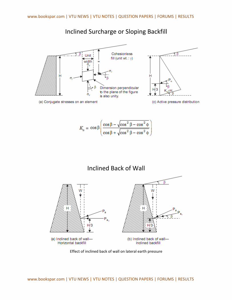
Inclined Surcharge or Sloping Backfill
Inclined Back of Wall
Effect of inclined back of wall on lateral earth pressure

www.bookspar.com | VTU NEWS | VTU NOTES | QUESTION PAPERS | FORUMS | RESULTS
www.bookspar.com | VTU NEWS | VTU NOTES | QUESTION PAPERS | FORUMS | RESULTS
Earth Pressure of Cohesive Soil
A cohesive soil is partially self-supporting and it will, therefore, exert a smaller pressure on a retaining wall than a cohesionless soil with the same angle of friction and density. Cohesion is known to increase the passive earth resistance of a soil.
The lateral pressure distribution diagram is as shown
Active pressure distribution for a cohesive soil Passive pressure distribution for the cohesive soil
Here Nφ = tan2 (45° + φ/2),called ‘flow value’.
The negative values of active pressure up to a depth equal to half of the so-called ‘critical depth’ indicate suction effect or tensile stresses; however, it is well known that soils cannot withstand tensile stresses and hence, suction is unlikely to occur. Invariably, the pressure from the surface in the tension zone is ignored.
The net pressure over depth of 2 Zc is obviously zero. This indicates that a cohesive soil mass should be able to stand unsupported up to this depth which is known as the critical depth and is given by

www.bookspar.com | VTU NEWS | VTU NOTES | QUESTION PAPERS | FORUMS | RESULTS
www.bookspar.com | VTU NEWS | VTU NOTES | QUESTION PAPERS | FORUMS | RESULTS
COULOMB’S WEDGE THEORY
Charles Augustine Coulomb (1776), a famous French scientist and military engineer, was the first to try to give a scientific basis to the hazy and arbitrary ideas existing in his time regarding lateral earth pressure on walls.
Coulomb’s theory considers the soil behind the wall as a whole instead of as an element in the soil. If a wall supporting a granular soil were not to be there, the soil will slump down to its angle of repose or internal friction. It is therefore reasonable to assume that if the wall only moved forward slightly a rupture plane would develop somewhere between the wall and the surface of repose. The triangular mass of soil between this plane of failure and the back of the wall is referred to as the ‘sliding wedge’. It is reasoned that, if the retaining wall were suddenly removed, the soil within the sliding wedge would slump downward. Therefore, an analysis of the forces acting on the sliding wedge at incipient failure will reveal the thrust from the lateral earth pressure which is necessary for the wall to withstand in order to hold the soil mass in place. This is why Coulomb’s theory is also called the ‘Wedge theory’, implying the existence of a plane rupture surface. However, Coulomb recognized the possibility of the existence of a curved rupture surface, although he considered a plane surface for the sake of mathematical simplicity. In fact, it is now established that the assumption of a plane rupture surface introduces significant error in the determination of passive earth resistance, a curved rupture surface being nearer to facts, as demonstrated by experiments.
In the course of time Coulomb’s theory underwent some alternations and new developments. The theory is very adaptable to graphical solution and the effects of wall friction and batter are automatically allowed for. Poncelet (1840), Culmann (1866), Rebhann (1871) and Engesser (1880) are the notable figures who contributed to further development of Coulomb’s theory.
The significance of Coulomb’s work may be recognized best by the fact that his ideas on earth pressure still prevail in their principal points with a few exceptions and are considered valid even today in the design of retaining walls.
Assumptions
The primary assumptions in Coulomb’s wedge theory are as follows:
• The backfill soil is considered to be dry, homogeneous and isotropic; it is elastically un-deformable but breakable, granular material, possessing internal friction but no cohesion.

www.bookspar.com | VTU NEWS | VTU NOTES | QUESTION PAPERS | FORUMS | RESULTS
www.bookspar.com | VTU NEWS | VTU NOTES | QUESTION PAPERS | FORUMS | RESULTS
• The rupture surface is assumed to be a plane for the sake of convenience in analysis. It passes through the heel of the wall. It is not actually a plane, but is curved and this is known to Coulomb.
• The sliding wedge acts as a rigid body and the value of the earth thrust is obtained by considering its equilibrium.
• The position and direction of the earth thrust are assumed to be known. The thrust acts on the back of the wall at a point one-third of the height of the wall above the base of the wall and makes an angle δ, with the normal to the back face of the wall. This is an angle of friction between the wall and backfill soil and is usually called ‘wall friction’.
• The problem of determining the earth thrust is solved, on the basis of two-dimensional case of ‘plane strain’. This is to say that, the retaining wall is assumed to be of great length and all conditions of the wall and fill remain constant along the length of the wall. Thus, a unit length of the wall perpendicular to the plane of the paper is considered.
• When the soil wedge is at incipient failure or the sliding of the wedge is impending, the theory gives two limiting values of earth pressure, the least and the greatest (active and passive), compatible with equilibrium.
The additional inherent assumptions relevant to the theory are as follows:
• The soil forms a natural slope angle, φ, with the horizontal, without rupture and sliding. This is called the angle of repose and in the case of dry cohesionless soil; it is nothing but the angle of internal friction.
• If the wall yields and the rupture of the backfill soil take place, a soil wedge is torn off from the rest of the soil mass. In the active case, the soil wedge slides sideways and downward over the rupture surface, thus exerting a lateral pressure on the wall. In the case of passive earth resistance, the soil wedge slides sideways and upward on the rupture surface due to the forcing of the wall against the fill.
• For a rupture plane within the soil mass, as well as between the back of the wall and the soil, Newton’s law of friction is valid (that is to say, the shear force developed due to friction is the coefficient of friction times the normal force acting on the plane). This angle of friction, whose tangent is the coefficient of friction, is dependent upon the physical properties of the materials involved.
• The friction is distributed uniformly on the rupture surface. • The back face of the wall is a plane.

www.bookspar.com | VTU NEWS | VTU NOTES | QUESTION PAPERS | FORUMS | RESULTS
www.bookspar.com | VTU NEWS | VTU NOTES | QUESTION PAPERS | FORUMS | RESULTS
Among the infinitely large number of rupture surface that may be passed through the heel of the wall, the most dangerous one is that for which the active earth thrust is a maximum (the wall must resist even the greatest value to be stable).
In the case of passive earth resistance, the most dangerous rupture surface is the one for which the resistance is a minimum. The minimum force necessary to tear off the soil wedge from the soil mass when the wall is forced against the soil is thus the criterion, since failure is sure to occur at greater force. Note that this is in contrast to the minimum and maximum for active and passive cases in relation to the movement of the wall away from or towards the fill, respectively.
Also note that Coulomb’s theory treats the soil mass in the sliding wedge in its entirety. The assumptions permit one to treat the problem as a statically determinate one.
Coulomb’s theory is applicable to inclined wall faces, to a wall with a broken face, to a sloping backfill curved backfill surface, broken backfill surface and to concentrated or distributed surcharge loads.
One of the main deficiencies in Coulomb’s theory is that, in general, it does not satisfy the static equilibrium condition occurring in nature. The three forces (weight of the sliding wedge, earth pressure and soil reaction on the rupture surface) acting on the sliding wedge do not meet at a common point, when the sliding surface is assumed to be planar. Even the wall friction was not originally considered but was introduced only some time later.
Regardless of this deficiency and other assumptions, the theory gives useful results in practice; however, the soil constants should be determined as accurately as possible.
www.bookspar.com | VTU NEWS | VTU NOTES | QUESTION PAPERS | FORUMS | RESULTS
www.bookspar.com | VTU NEWS | VTU NOTES | QUESTION PAPERS | FORUMS | RESULTS
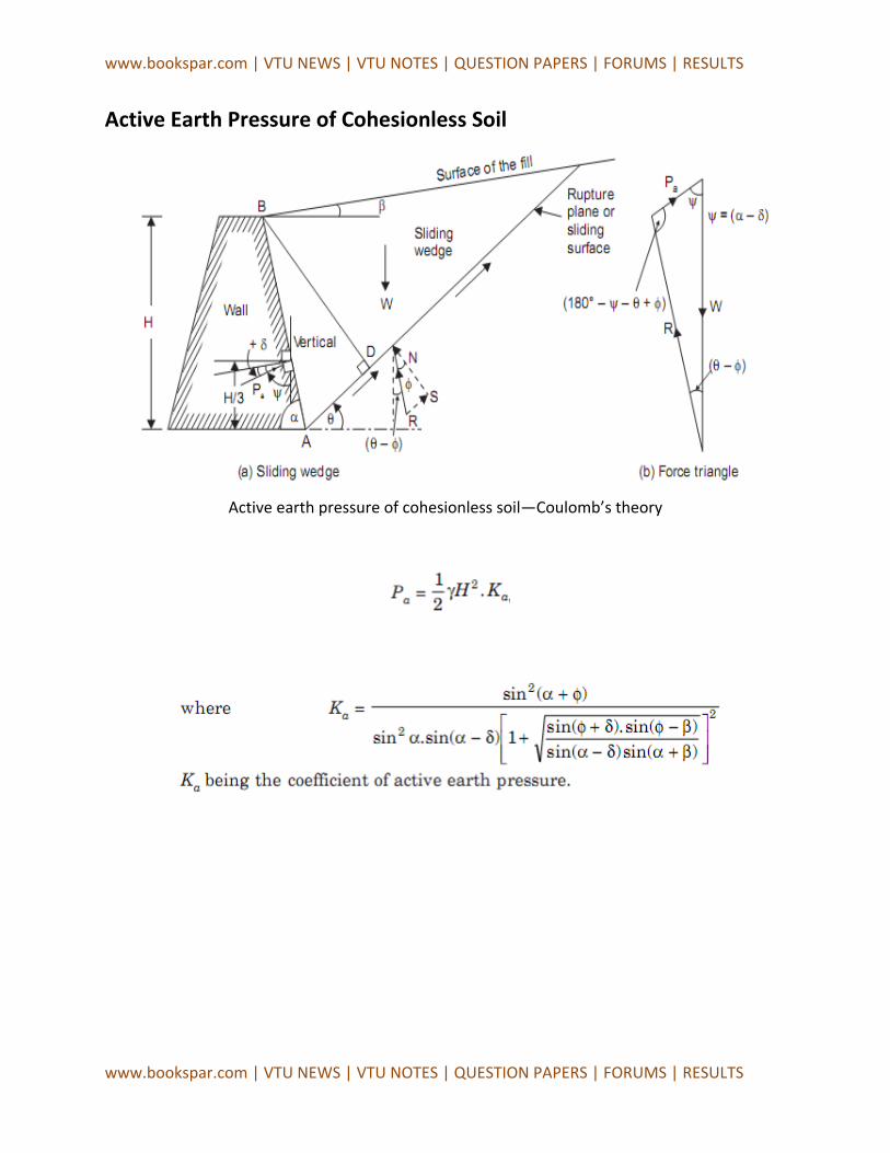
Active Earth Pressure of Cohesionless Soil
Active earth pressure of cohesionless soil—Coulomb’s theory

www.bookspar.com | VTU NEWS | VTU NOTES | QUESTION PAPERS | FORUMS | RESULTS
www.bookspar.com | VTU NEWS | VTU NOTES | QUESTION PAPERS | FORUMS | RESULTS
Passive Earth Pressure of Cohesionless Soil
Passive earth pressure of cohesionless soil—Coulomb’s theory
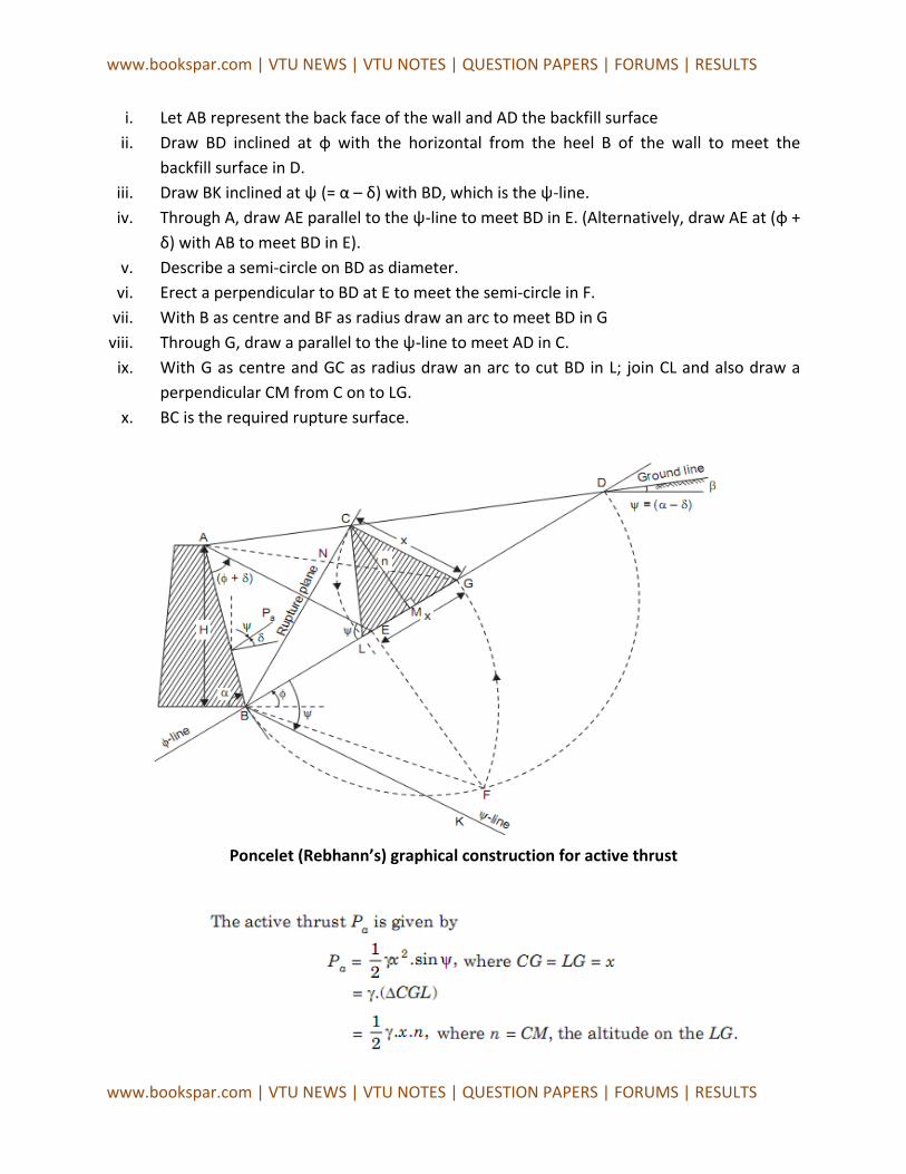
REBHANN’S GRAPHICAL METHOD Rebhann (1871) is credited with having presented the criterion for the direct location of the failure plane assumed in the Coulomb’s theory.
The steps involved in the graphical method are as follows, with reference to Fig shown
www.bookspar.com | VTU NEWS | VTU NOTES | QUESTION PAPERS | FORUMS | RESULTS
www.bookspar.com | VTU NEWS | VTU NOTES | QUESTION PAPERS | FORUMS | RESULTS
i. Let AB represent the back face of the wall and AD the backfill surface ii. Draw BD inclined at φ with the horizontal from the heel B of the wall to meet the
backfill surface in D. iii. Draw BK inclined at ψ (= α – δ) with BD, which is the ψ-line. iv. Through A, draw AE parallel to the ψ-line to meet BD in E. (Alternatively, draw AE at (φ +
δ) with AB to meet BD in E). v. Describe a semi-circle on BD as diameter.
vi. Erect a perpendicular to BD at E to meet the semi-circle in F. vii. With B as centre and BF as radius draw an arc to meet BD in G
viii. Through G, draw a parallel to the ψ-line to meet AD in C. ix. With G as centre and GC as radius draw an arc to cut BD in L; join CL and also draw a
perpendicular CM from C on to LG. x. BC is the required rupture surface.
Poncelet (Rebhann’s) graphical construction for active thrust

www.bookspar.com | VTU NEWS | VTU NOTES | QUESTION PAPERS | FORUMS | RESULTS
www.bookspar.com | VTU NEWS | VTU NOTES | QUESTION PAPERS | FORUMS | RESULTS
CULMANN’S GRAPHICAL METHOD
Karl Culmann (1866) gave his own graphical method to evaluate the earth pressure from Coulomb’s theory. Culmann’s method permits one to determine graphically the magnitude of the earth pressure and to locate the most dangerous rupture surface according to Coulomb’s wedge theory. This method has more general application than Poncelet’s and is, in fact, a simplified version of the more general trial wedge method. It may be conveniently used for ground surface of any shape, for different types of surcharge loads, and for layered backfill with different unit weights for different layers.
Culmann’s graphical method for active thrust
The steps in the construction may be set out as follows:
i. Draw the ground line, φ-line, and ψ-line, and the wall face AB. ii. Choose an arbitrary failure plane BC1. Calculate weight of the wedge ABC and plot it as
B-1 to a convenient scale on the φ-line. iii. Draw 1 – 1′ parallel to the ψ-line through 1 to meet BC1 in 1′. 1′ is a point on the
Culmann-line.

www.bookspar.com | VTU NEWS | VTU NOTES | QUESTION PAPERS | FORUMS | RESULTS
www.bookspar.com | VTU NEWS | VTU NOTES | QUESTION PAPERS | FORUMS | RESULTS
iv. Similarly, take some more failure planes BC2, BC3, ..., and repeat the steps (ii) and (iii) to establish points 2′, 3′, ...
v. Join B, 1′, 2′, 3′, etc., smoothly to obtain the Culmann curve. vi. Draw a tangent t-t, to the Culmann line parallel to the φ-line.
vii. Let the point of the tangency be F′ viii. Draw F′F parallel to the ψ-line to meet the φ-line in F.
ix. Join BF′ and produce it to meet the ground line in C. x. BF′C represents the failure surface and FF ′ represents Pa to the same scale as that
chosen to represent the weights of wedges.
If the upper surface of the backfill is a plane, the weights of wedges will be proportional to the distances l1, l2 ... (bases), since they have a common-height, H1. Thus B-1, B-2, etc ..., may be made equal or proportional to l1, l2, etc. The sector scale may be easily obtained by comparing BF with the weight of wedge ABC.
COMPARISON OF COULOMB’S THEORY WITH RANKINE’S THEORY (i) Coulomb considers a retaining wall and the backfill as a system; he takes into account the friction between the wall and the backfill, while Rankine does not.
(ii) The backfill surface may be plane or curved in Coulomb’s theory, but Rankine’s allows only for a plane surface.
(iii) In Coulomb’s theory, the total earth thrust is first obtained and its position and direction of the earth pressure are assumed to be known; linear variation of pressure with depth is tacitly assumed and the direction is automatically obtained from the concept of wall friction. In Rankine’s theory, plastic equilibrium inside a semi-infinite soil mass is considered, pressures evaluated, a retaining wall is imagined to be interposed later, and the location and magnitude of the total earth thrust are established mathematically.
(iv) Coulomb’s theory is more versatile than Rankine’s in that it can take into account any shape of the backfill surface, break in the wall face or in the surface of the fill, effect of stratification of the backfill, effect of various kinds of surcharge on earth pressure, and the effects of cohesion, adhesion and wall friction. it lends itself to elegant graphical solutions and gives more reliable results, especially in the determination of the passive earth resistance; this is in-spite of the fact that static equilibrium condition does not appear to be satisfied in the analysis.
(v) Rankine’s theory is relatively simple and hence is more commonly used, while Coulomb’s theory is more rational and versatile although cumbersome at times; therefore, the use of the latter is called for in important situations or problems.