Embed Size (px)
Citation preview
Lasercom From Mars: Orbiters, Landers, and CubeSats
H. Hemmati and A. Biswas Jet Propulsion Laboratory,
California Institute of Technology, Pasadena, CA, USA [email protected]
Abstract Numerous successful near-Earth laser communications (lasercom) link demonstrations have been made. The next challenge is to demonstrate deep-space links from asteroids, comets, and planets to Earth. In this paper we describe recent concepts for communications from spacecraft visiting planet Mars. Communications links, including trunk line from Mars orbiting spacecraft, and from small lasercom terminals on Mars landed assets or onboard interplanetary CubeSats to Mars are discussed. Uplink communications with some of these flight terminals are also described. Substantial gains are shown over conventional telecommunications, given equivalent mass and power consumption at the spacecraft, and typically one tenth the aperture diameter
Keywords - Optical communications, laser communications
I. INTRODUCTION Substantial enhancement of the current NASA telecom link capacity is needed to return larger volumes of science data, and to prepare for future human deep-space exploration missions. This has been the primary in considering lasercom as the means of augmenting spacecraft communications. Near-Earth laser communications have been demonstrated successfully and repeatedly over the past two decades [1]. However, the challenges presented by deep space optical links require dedicated risk retiring technology demonstration(s) prior to operational use of the technology. Fig. 1 plots link difficulty [data rate (Mb/s) x distance squared (AU)2] in dB, for some missions vs. data rate, where 0 dB link difficulty represents 100 Mb/s from lunar distance [2].
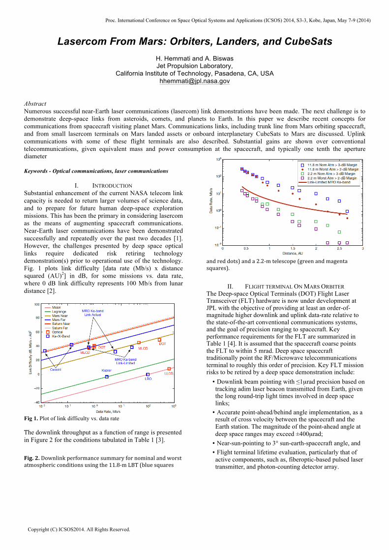
Fig 1. Plot of link difficulty vs. data rate The downlink throughput as a function of range is presented in Figure 2 for the conditions tabulated in Table 1 [3].
Fig. 2. Downlink performance summary for nominal and worst atmospheric conditions using the 11.8-‐m LBT (blue squares
and red dots) and a 2.2-‐m telescope (green and magenta squares).
II. FLIGHT TERMINAL ON MARS ORBITER The Deep-space Optical Terminals (DOT) Flight Laser Transceiver (FLT) hardware is now under development at JPL with the objective of providing at least an order-of-magnitude higher downlink and uplink data-rate relative to the state-of-the-art conventional communications systems, and the goal of precision ranging to spacecraft. Key performance requirements for the FLT are summarized in Table 1 [4]. It is assumed that the spacecraft coarse points the FLT to within 5 mrad. Deep space spacecraft traditionally point the RF/Microwave telecommunications terminal to roughly this order of precision. Key FLT mission risks to be retired by a deep space demonstration include:
• Downlink beam pointing with ≤1µrad precision based on tracking adim laser beacon transmitted from Earth, given the long round-trip light times involved in deep space links;
• Accurate point-ahead/behind angle implementation, as a result of cross velocity between the spacecraft and the Earth station. The magnitude of the point-ahead angle at deep space ranges may exceed ±400µrad;
• Near-sun-pointing to 3° sun-earth-spacecraft angle, and • Flight terminal lifetime evaluation, particularly that of active components, such as, fiberoptic-based pulsed laser transmitter, and photon-counting detector array.
Proc. International Conference on Space Optical Systems and Applications (ICSOS) 2014, S3-3, Kobe, Japan, May 7-9 (2014)
Copyright (C) ICSOS2014. All Rights Reserved.
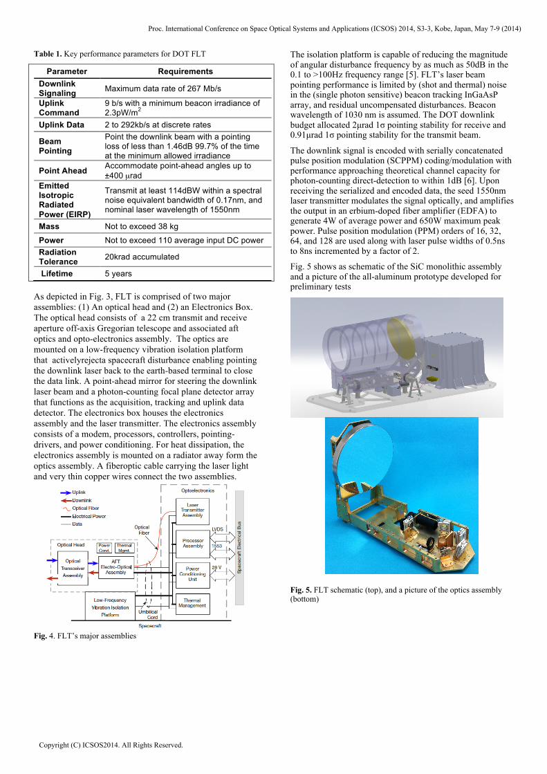
Table 1. Key performance parameters for DOT FLT
Parameter Requirements Downlink Signaling Maximum data rate of 267 Mb/s
Uplink Command
9 b/s with a minimum beacon irradiance of 2.3pW/m2
Uplink Data 2 to 292kb/s at discrete rates
Beam Pointing
Point the downlink beam with a pointing loss of less than 1.46dB 99.7% of the time at the minimum allowed irradiance
Point Ahead Accommodate point-ahead angles up to ±400 µrad
Emitted Isotropic Radiated Power (EIRP)
Transmit at least 114dBW within a spectral noise equivalent bandwidth of 0.17nm, and nominal laser wavelength of 1550nm
Mass Not to exceed 38 kg
Power Not to exceed 110 average input DC power Radiation Tolerance 20krad accumulated
Lifetime 5 years
As depicted in Fig. 3, FLT is comprised of two major assemblies: (1) An optical head and (2) an Electronics Box. The optical head consists of a 22 cm transmit and receive aperture off-axis Gregorian telescope and associated aft optics and opto-electronics assembly. The optics are mounted on a low-frequency vibration isolation platform that activelyrejecta spacecraft disturbance enabling pointing the downlink laser back to the earth-based terminal to close the data link. A point-ahead mirror for steering the downlink laser beam and a photon-counting focal plane detector array that functions as the acquisition, tracking and uplink data detector. The electronics box houses the electronics assembly and the laser transmitter. The electronics assembly consists of a modem, processors, controllers, pointing-drivers, and power conditioning. For heat dissipation, the electronics assembly is mounted on a radiator away form the optics assembly. A fiberoptic cable carrying the laser light and very thin copper wires connect the two assemblies.
Fig. 4. FLT’s major assemblies
The isolation platform is capable of reducing the magnitude of angular disturbance frequency by as much as 50dB in the 0.1 to >100Hz frequency range [5]. FLT’s laser beam pointing performance is limited by (shot and thermal) noise in the (single photon sensitive) beacon tracking InGaAsP array, and residual uncompensated disturbances. Beacon wavelength of 1030 nm is assumed. The DOT downlink budget allocated 2µrad 1σ pointing stability for receive and 0.91µrad 1σ pointing stability for the transmit beam.
The downlink signal is encoded with serially concatenated pulse position modulation (SCPPM) coding/modulation with performance approaching theoretical channel capacity for photon-counting direct-detection to within 1dB [6]. Upon receiving the serialized and encoded data, the seed 1550nm laser transmitter modulates the signal optically, and amplifies the output in an erbium-doped fiber amplifier (EDFA) to generate 4W of average power and 650W maximum peak power. Pulse position modulation (PPM) orders of 16, 32, 64, and 128 are used along with laser pulse widths of 0.5ns to 8ns incremented by a factor of 2.
Fig. 5 shows as schematic of the SiC monolithic assembly and a picture of the all-aluminum prototype developed for preliminary tests
Fig. 5. FLT schematic (top), and a picture of the optics assembly (bottom)
Proc. International Conference on Space Optical Systems and Applications (ICSOS) 2014, S3-3, Kobe, Japan, May 7-9 (2014)
Copyright (C) ICSOS2014. All Rights Reserved.
III. GROUND TERMINAL
The ground terminal planned for technology demonstration is one of the existing large diameter telescopes (such as the 5m Hale/Palomar telescope, or the 11.8m effective diameter large binocular telescope). For extended operational use dedicated laser communications telescopes, ideally with an aperture diameter of at least 10m) for downlink data reception will be sued. A smaller diameter (about 1m) telescope is adequate for uplink beacon and data transmission. The received signal is collected and focused onto a WSi superconducting nanowire detector array held at <1°K temperature. The detected signal then passes through a
series of electronics for de-interleaving, and synchronization, and decoding [7].
The uplink laser beam with a total power of nearly 5kW for the Mars farthest distance carries the uplink data, and is supplied to the spacecraft in the form of 8 to 10 mutually incoherent beams to largely mitigate the atmospheric turbulence effects near the telescope. Typical beam divergence is 40µrad. The uplink telescope is tasked with directing this highly collimated beam to the spacecraft with an accuracy of 16 µrad to minimize the beam pointing losses [8]. JPL’s 1-meter diameter lasercom-dedicated telescope located in Wrightwood, California is envisioned as the uplink beacon/data provider to the spacecraft.
Fig. 6. Attenuation of laser beams traversing the Mars atmosphere as a function of elevation angle, and laser’s wavelength. A small (2.2cm) aperture lasercom transceiver for the Mars surface was developed and its link properties at 200 Mb/s data rate and acquisition and tracking functions were successfully tested in links with a terminal in an airplane that depicted a terminal onboard a Mars orbiting spacecraft [11]
IV. LINKS FROM THE MARS SURFACE
Optical proximity links at Mars (from a surface lander/rover to an orbiter) have the potential to return streaming video from the surface. Compressed HDTV quality video transmission at 20-30 Mb/s with 45 Gb/sol to 2.25 Tb/sol of data-volume is feasible, assuming 25 minutes of contact time. In comparison, the current UHF link to the MRO spacecraft averages at 0.7 Gb/sol.
Dust in the Mars atmosphere causes significant optical attenuation for proximity links to orbiters and direct-to-Earth (DTE) links from the Mars surface [9]. Additionally, Mars dust may contaminate the optical surfaces causing degradation of optical transmission. Measurement-based analysis indicates that 90% of the time Mars atmospheric optical density is less than 1.0 [10]. Fig. 6 shows Mars atmospheric attenuation estimated using existing models, as a function of dust density, laser wavelength and elevation angle. Our link analyses assumes that free-space optical communication link design can handle the attenuation corresponding to optical densities of 1.0 at zenith angles of 80°. As attenuation gets worse the data volume transfer will
decrease with nearly complete outage expected during dust storms (OD of 4.0 or higher) [9].
V. LASERCOM WITH MARS CUBESAT
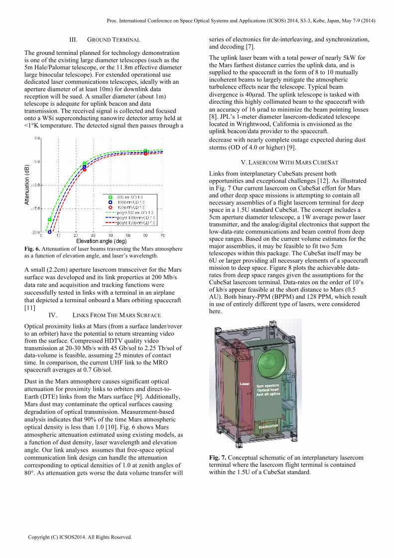
Links from interplanetary CubeSats present both opportunities and exceptional challenges [12]. As illustrated in Fig. 7 Our current lasercom on CubeSat effort for Mars and other deep space missions is attempting to contain all necessary assemblies of a flight lasercom terminal for deep space in a 1.5U standard CubeSat. The concept includes a 5cm aperture diameter telescope, a 1W average power laser transmitter, and the analog/digital electronics that support the low-data-rate communications and beam control from deep space ranges. Based on the current volume estimates for the major assemblies, it may be feasible to fit two 5cm telescopes within this package. The CubeSat itself may be 6U or larger providing all necessary elements of a spacecraft mission to deep space. Figure 8 plots the achievable data-rates from deep space ranges given the assumptions for the CubeSat lasercom terminal. Data-rates on the order of 10’s of kb/s appear feasible at the short distance to Mars (0.5 AU). Both binary-PPM (BPPM) and 128 PPM, which result in use of entirely different type of lasers, were considered here.
Fig. 7. Conceptual schematic of an interplanetary lasercom terminal where the lasercom flight terminal is contained within the 1.5U of a CubeSat standard.
Proc. International Conference on Space Optical Systems and Applications (ICSOS) 2014, S3-3, Kobe, Japan, May 7-9 (2014)
Copyright (C) ICSOS2014. All Rights Reserved.
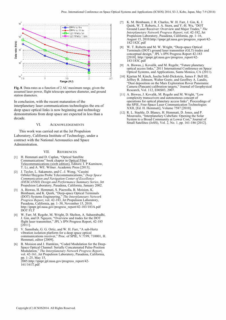
Fig. 8. Data-rates as a function of 2 AU maximum range, given the assumed laser power, flight telescope aperture diameter, and ground station diameters.
In conclusion, with the recent maturation of the interplanetary laser communications technologies the era of deep space optical links is now beginning and technology demonstrations from deep space are expected in less than a decade.
VI. ACKNOWLEDGEMENTS
This work was carried out at the Jet Propulsion Laboratory, California Institute of Technology, under a contract with the National Aeronautics and Space Administration.
VII. REFERENCES [1] H. Hemmati and D. Caplan, “Optical Satellite
Communications” book chapter in Optical Fiber Telecommunications (sixth edition), Editors: I. P Kaminow, T. Li, and A. WE. Wilner. Academic Press [2013].
[2] J. Taylor, L. Sakamoto, and C.-J. Wong, “Cassini Orbiter/Huygens Probe Telecommunications,” Deep Space Communication and Navigation Center of Excellence (DESCANSO) Design and Performance Summary Series, Jet Propulsion Laboratory, Pasadena, California, January 2002.
[3] A. Biswas, H. Hemmati, S. Piazzolla, B. Moision, K. Birnbaum, and K. Quirk, “Deep-space Optical Terminals (DOT) Systems Engineering,” The Interplanetary Network Progress Report, vol. 42-183, Jet Propulsion Laboratory, Pasadena, California, pp. 1–38, November 15, 2010. http://ipnpr.jpl.nasa.gov/progress_report/42-183/183A.pdf DOT FLT
[4] W. Farr, M. Regehr, M. Wright, D. Shelton, A. Sahasrabudhi, J. Gin, and D. Nguyen, “Overview and trades for the DOT flight laser transmitter,” JPL’s IPN Progress Report, 42-185 [2011].
[5] V. Sannibale, G. G. Ortiz, and W. H. Farr, “A sub-Hertz vibration isolation platform for a deep space optical communications receiver,” Proc. of SPIE, V.7199, 710001, H. Hemmati, editor [2009].
[6] B. Moision and J. Hamkins, “Coded Modulation for the Deep-Space Optical Channel: Serially Concatenated Pulse-Position Modulation,” The Interplanetary Network Progress Report, vol. 42-161, Jet Propulsion Laboratory, Pasadena, California, pp. 1–25, May 15, 2005.http://ipnpr.jpl.nasa.gov/progress_report/42-161/161T.pdf
[7] K. M. Birnbaum, J. R. Charles, W. H. Farr, J. Gin, K. J. Quirk, W. T. Roberts, J. A. Stern, and Y.-H. Wu, “DOT Ground Laser Receiver: Overview and Major Trades,” The Interplanetary Network Progress Report, vol. 42-182, Jet Propulsion Laboratory, Pasadena, California, pp. 1–16, August 15, 2010.http://ipnpr.jpl.nasa.gov/progress_report/42-182/182C.pdf
[8] W. T. Roberts and M. W. Wright, “Deep-space Optical Terminals (DOT) ground laser transmitter (GLT) trades and conceptual design,” JPL’s IPN Progress Report 42-183 [2010]. http://ipnpr.jpl.nasa.gov/progress_report/42-183/183C.pdf
[9] A. Biswas, j. Kovalik, and M. Regehr, “Future planetary optical access links,” 2011 International Conference on Space Optical Systems, and Applications, Santa Monica, CA (2011).
[10] Kjartan M. Kinch, Jascha Sohl-Dickstein, James F. Bell III, Jeffrey R. Johnson, Walter Goetz, and Geoffrey A. Landis, “Dust deposition on the Mars Exploration Rover Panoramic Camera (Pancam) calibration targets,“ Journal of Geophysical Research, Vol. 112, E06S03, 2007.
[11] A. Biswas, J. Kovalik, M. Regehr and M. Wright, “Low complexity transceivers and autonomous concept of operations for optical planetary access links”, Proceedings of the SPIE, Free-Space Laser Communication Technologies XXII, [Ed. H. Hemmati], Volume 7587 [2010].
[12] R. L. Staehle, D. Blaney, H. Hemmati, D. Jones, and P. Mouroulis, “Interplanetary CubeSats: Opening the Solar System to a Broad Community at Lower Cost," Journal of Small Satellites (JoSS), Vol. 2, No. 1, pp. 161-186 [2012].
Proc. International Conference on Space Optical Systems and Applications (ICSOS) 2014, S3-3, Kobe, Japan, May 7-9 (2014)
Copyright (C) ICSOS2014. All Rights Reserved.