Embed Size (px)
Citation preview

OPERATOR’S MANUAL
B-70264EN/02
� No part of this manual may be reproduced in any form.
� All specifications and designs are subject to change without notice.
In this manual we have tried as much as possible to describe all thevarious matters.However, we cannot describe all the matters which must not be done,or which cannot be done, because there are so many possibilities.Therefore, matters which are not especially described as possible inthis manual should be regarded as ”impossible”.
B-70264EN/02 SAFETY PRECAUTIONS
s-1
SAFETY PRECAUTIONSThis manual contains precautions which must be observed duringoperation and maintenance of the laser oscillator to ensure the safetyof the operator and maintenance personnel and prevent damage to theoscillator.Maintenance involves a variety of risks and, therefore, must beconducted by those personnel who have sufficiently trained inmaintenance and safety.Besides the laser oscillator, the laser machining system contains amachine, power magnetics cabinet, servo system, CNC, and operator'spanel. This manual describes the laser oscillator. For a description ofnotes other than those on the oscillator, refer to the correspondingmanuals, supplied by the machine tool builder and FANUC.
Contents1.1 DEFINITION OF WARNING, CAUTION, AND NOTE.........s-21.2 WARNINGS AND CAUTIONS ON EXPOSURE ...................s-31.3 WARNINGS AND CAUTIONS ON MAINTENANCE...........s-51.4 WARNINGS AND CAUTIONS ON HANDLING...................s-61.5 WARNINGS AND CAUTIONS ON MACHINING.................s-8

SAFETY PRECAUTIONS B-70264EN/02
s-2
1.1 DEFINITION OF WARNING, CAUTION, AND NOTE
To ensure the safety of maintenance personnel (referred to as users)and prevent damage to the machine, this manual indicates eachprecaution on safety with "Warning" or "Caution" according to itsseverity.Supplementary information is indicated by "Note".Read the contents of each "Warning", "Caution", and "Note" beforeattempting to use the oscillator.
WARNINGApplied when there is a danger of the user beinginjured or when there is a danger of both the userbeing injured and the equipment being damaged ifthe approved procedure is not observed.
CAUTIONApplied when there is a danger of the equipmentbeing damaged, if the approved procedure is notobserved.
NOTENotes is used to indicate supplementaryinformation other than Warnings and Cautions.
• Read this manual carefully, and store it in a safe place.

B-70264EN/02 SAFETY PRECAUTIONS
s-3
1.2 WARNINGS AND CAUTIONS ON EXPOSURE
WARNING1 It is extremely dangerous to expose your eyes to direct,
scattered, or reflected CO2 laser light. Always wearprotective glasses while the laser is operating.Exposure to laser light can cause blindness. If your eyesare accidentally exposed, seek medical adviceimmediately.
2 Do not turn on the laser oscillator while a panel is removedor a door is open.Operating the laser with a door open or panel removed mayresult in the operator being directly exposed to CO2 laserradiation. Exposure to laser light can cause blindnessand/or severe burns. If your eyes are accidentally exposedto laser light, seek medical advice immediately.Before turning on the power during maintenance ifabsolutely necessary, wear protective glasses and clothingto prevent accidents.
3 Surround the laser machining tool with a fence made of amaterial which absorbs laser light well (such as acrylic).Place appropriate warning notices on the fence.The door in the safety fence shall be fitted with an interlockswitch such that opening the door stops the laser.Failure to provide such a fence exposes persons in thevicinity of the machine tool to the danger of being exposedto CO2 laser radiation and the associated risk of blindness.If a person is accidentally exposed to laser light, seekmedical advice immediately.
4 If the laser oscillator is operated with a panel open,ultraviolet radiation is emitted from the high-frequencydischarge section. Gazing the discharge section for a longtime can cause visual disturbances such as impairedeyesight.Always wear protective glasses during work. If you feeltrouble with your eyes, seek medical advice immediately.
5 The laser beam shall be no higher than average eye height.Enclose the path of the laser beam with covers. Do notleave the end of the beam path open. Place laser-absorbing material at the end of the beam path to absorbthe beam's energy.A CO2 laser beam is directional and has a high energydensity. Exposure to laser light can cause blindness.Flammable material may burn or explode if exposed to thelaser beam. If your eyes are accidentally exposed to laserlight, seek medical advice immediately.

SAFETY PRECAUTIONS B-70264EN/02
s-4
WARNING6 If there is a possibility of being exposed to CO2 laser
radiation exceeding the maximum permissible exposure(MPE) level for skin, wear protective clothing.Otherwise, there is a danger of being burnt.
7 The oscillator is fitted with a red semiconductor laser toindicate the approximate position of invisible CO2 laserbeam. Do not look directly at the semiconductor laserbeam. Otherwise, your eyes may be injured.
NOTE1 Warning labels are affixed to those parts of the laser
oscillator where there is a danger of exposure to laserradiation. Observe the precautions given on the labels.
2 During installation or maintenance necessitating theopening of an oscillator door or the removal of a panel, onlypersons who have undergone maintenance training shouldoperate the laser. In such a case, extreme caution must beexercised.
3 Laser products shall conform to the regulations laid down inthe laser safety standard, including that stipulating controlusing a key.The oscillator start signal (RUN ON) shall be controlled witha key switch such that the oscillator cannot be turned onwithout a specific key.Control using a key ensures that other than the authorizedpersonnel cannot operate the laser oscillator. It is extremelydangerous if a person who is unfamiliar with the equipmentattempts to operate the laser oscillator.The shutter shall be unlocked only while a beam is beingoutput. Otherwise, keep the shutter locked to provideprotection should the laser accidentally be turned on.The laser oscillator is equipped with a warning light as anoption. The warning light blinks while discharge is inprogress or whenever laser radiation is possible.While the warning light is blinking, pay careful attention tolaser radiation and high voltages.

B-70264EN/02 SAFETY PRECAUTIONS
s-5
1.3 WARNINGS AND CAUTIONS ON MAINTENANCE
WARNING1 A high voltage of 3 to 4 kV0-p is applied to some places in
the laser oscillator cabinet. Therefore, do not turn the powerto the oscillator on or operate the oscillator when anoscillator panel is open. Operating the laser oscillator with apanel open can cause a touch on a high-voltage place,resulting in electric shock.
2 Before daily inspection, the replacement of a maintenancepart or maintenance, open the main circuit breaker and turnthe power supply off (double power-off).To prevent the power from being inadvertently turned on,lock the circuit breaker open, and affix an indication of workin progress. Before turning on the power duringmaintenance if absolutely necessary, take measures forsafety.
3 The gas circulating system in the oscillator becomes veryhot.Do not touch the gas pipes, turbo blower, heat exchanger,or exhaust pump, until they have cooled down sufficientlyafter the oscillator has been turned off. Otherwise, you maybe burnt.
4 The oscillator contains cooling fan units. Although the fanunits are fitted with a finger guard, to prevent injury, keepyour hands well away from the fans.

SAFETY PRECAUTIONS B-70264EN/02
s-6
1.4 WARNINGS AND CAUTIONS ON HANDLING
WARNING1 The oscillator output mirror and focusing lens on the
machining head both have a substrate made of ZnSe (zincselenide), a toxic substance. Therefore, do not touch themirror or lens with your bare hands if it is damaged.Inhaling ZnSe dust may cause difficulty in breathing,completely stopping the breathing of the victim in the worstcase.If you accidentally touch the mirror or lens with your barehands, wash your hands well under running water.If you accidentally inhale ZnSe dust or debris, seek medicaladvice immediately.
2 If the laser oscillator must be moved, entrust the work to themachine tool builder whenever possible. If performed byinexperienced personnel, the oscillator may topple or bedropped, resulting in a potentially fatal accident.
When the machine tool builder is not available to move theoscillator, follow the procedure described on the hangingmethod label. While moving the oscillator, stand well clearand never pass under the oscillator.
3 Do not allow any dangerous or high-pressure gas to get intothe oscillator housing. The oscillator cabinet has a hermeticstructure (dustproof and dripproof), it cannot be ventilatedeasily.1) Flammable gases such as oxygen can cause a fire or
explosion.2) Toxic gases can harm operators during maintenance.3) Organic gases can degrade machining performance.4) High-pressure gases can damage a panel or the cabinet,
resulting in injury from flying matters.If such a gas accidentally gets into the oscillator housing,remove a panel for ventilation. The installation room mustbe also well ventilated.To purge the oscillator housing, use purified, low-pressureair or nitrogen.
4 Those who use a cardiac pacemaker must avoidmaintenance and inspection work during the discharge ofthe oscillator because the electromagnetic wavesgenerated during the discharge may affect the operation ofthe pacemaker.If you feel sick or out of condition, either immediately leavethe spot or stop operation.

B-70264EN/02 SAFETY PRECAUTIONS
s-7
CAUTION1 The oscillator is controlled according to the CNC internal
parameter settings. If a numeric value different from asetting is entered and the oscillator is operated, theoscillator may malfunction. In the worst case, the oscillatormay be damaged.
2 Use laser gas with the specified correct composition ratios.If you use laser gas with different specifications by mistake,performance degradation or an alarm will result. In theworst case, the oscillator may be damaged.
3 If storing the laser oscillator for a long time or leaving itunused for a long time, drain the inside of the oscillator.Otherwise, corrosion and clogging may result.Also drain the oscillator if it is likely to freeze in winter. If itfreezes, the water piping and cooling system componentswill be damaged.
NOTEDo not discard a used output mirror or focusing lenstogether with regular waste. If the output mirror or focusinglens is replaced, return the original to the supplier or entrustit to a specialized disposal company.

SAFETY PRECAUTIONS B-70264EN/02
s-8
1.5 WARNINGS AND CAUTIONS ON MACHINING
WARNING1 Do not look at the machining point without eye protection.
Otherwise, your eyes may be exposed to reflected laserlight, resulting in blindness.If your eyes are accidentally exposed to laser light, seekmedical advice immediately.
2 Before attempting to machine any material for the first time,consult with the manufacturer of the material.Some materials generate toxic gases when cut or drilled bya laser beam.Should you accidentally inhale any toxic gas, seek medicaladvice immediately.
3 The workpiece becomes very hot during machining. Nevertouch the workpiece with your bare hands. Otherwise, youmay be burnt.
4 During machining, extremely hot chips are likely to begenerated.Unless sufficient caution is exercised, there is a danger ofthe operator being burnt, or of a fire being started.
5 Some materials may burn or explode when laser machined.Before attempting to machine any material for the first time,consult with the manufacturer of the material, to prevent thedanger of fire of or the possibility of operator injury.
NOTE1 Do not place any flammable material (such as paper, cloth,
or wood) near the workpiece table.2 Keep a fire extinguisher beside the unit.

B-70264EN/02 PREFACE
p-1
PREFACEContents of the manual
This manual consists of the following chapters and appendixes:Chapter 1 : Notes on Use
Chapter 1 covers the operating environment conditions, coolingwater, laser gas, oscillator mirrors, and notification inaccordance with the Radio Law.
Chapter 2 : Handling the Laser BeamChapter 2 covers the warning labels affixed to the optical pathsin the oscillator and the oscillator itself.
Chapter 3 : Internal StructureChapter 3 describes the structure and operation of the laseroscillator.
Chapter 4 : MaintenanceChapter 4 describes daily maintenance and periodicmaintenance.It also describes maintenance software functions.
Chapter 5 : AlarmsChapter 5 describes the alarms generated if errors occur in thelaser oscillator.
Chapter 6 : Setting and Displaying DataChapter 6 describes the display and setting of diagnostic dataand parameters.
AppendixA. External ViewB. SpecificationsC. Glossary
Applicable modelsThis manual covers the following models. The followingabbreviations may be used in the text of this manual.
Model AbbreviationFANUC LASER C1000-MODEL E C1000-EFANUC LASER C2000-MODEL E C2000-EFANUC LASER C4000-MODEL E C4000-EFANUC LASER C5000-MODEL E C5000-EFANUC LASER C6000-MODEL E C6000-E
Related manualsThe following manuals are available for the FANUC LASER C1000/C2000/C4000/C5000/C6000-MODEL E
DESCRIPTIONS B-63662ENCONNECTION MANUAL B-63663ENOPERATOR’S MANUAL B-63664ENMAINTENANCE MANUAL B-63665EN
FANUC Series 16i-LB
PARAMETER MANUAL B-63670ENOPERATOR’S MANUAL(this manual)
B-70264ENFANUC LASER C1000/C2000/C4000/C5000/C6000 -MODEL E MAINTENANCE MANUAL B-70265EN


B-70264EN/02 TABLE OF CONTENTS
c-1
TABLE OF CONTENTS
SAFETY PRECAUTIONS...........................................................................s-1PREFACE ..................................................................................................p-11 NOTES ON USE ....................................................................................1
1.1 OPERATING ENVIRONMENT CONDITIONS............................................... 21.2 COOLING WATER........................................................................................ 31.3 LASER GAS .................................................................................................. 5
1.3.1 Laser gas specification .............................................................................................51.3.2 Supply Gas Pressure.................................................................................................51.3.3 Replacing the Laser Gas Cylinder............................................................................5
1.4 OSCILLATOR MIRRORS.............................................................................. 61.5 POWER CABLE ............................................................................................ 71.6 NOTIFICATION IN ACCORDANCE WITH THE RADIO LAW
(APPLICATION FOR PERMISSION OF HIGH-FREQUENCYEQUIPMENT) ................................................................................................ 9
2 HANDLING THE LASER BEAM ..........................................................102.1 WARNING LABELS..................................................................................... 112.2 OPTICAL PATHS IN THE OSCILLATOR.................................................... 20
3 INTERNAL STRUCTURE.....................................................................233.1 OUTLINE..................................................................................................... 243.2 INTERNAL STRUCTURE............................................................................ 26
4 MAINTENANCE ...................................................................................354.1 DAILY INSPECTION ................................................................................... 364.2 PERIODIC MAINTENANCE ........................................................................ 374.3 DETAILS OF MAINTENANCE..................................................................... 38
4.3.1 Turbo Blower Oil ...................................................................................................384.3.2 Exhaust Pump Oil...................................................................................................404.3.3 Exhaust Pump Filter ...............................................................................................414.3.4 Checking Operation Times.....................................................................................424.3.5 Automatic Aging ....................................................................................................44
4.4 MAINTENANCE PARTS LIST..................................................................... 45
5 ALARMS ..............................................................................................465.1 CHECKING THE ALARM OCCURRENCE STATUS .................................. 47

TABLE OF CONTENTS B-70264EN/02
c-2
5.2 LIST OF ALARMS ....................................................................................... 485.3 ALARM DETAILS ........................................................................................ 495.4 DISPLAY ITEMS ON THE DIAGNOSIS SCREEN ...................................... 61
5.4.1 Screen Display Operation ......................................................................................615.4.2 Signal Display on CNC-PMC (Machine Operator's Panel) ...................................615.4.3 Laser Oscillator Status Display..............................................................................63
6 SETTING AND DISPLAYING DATA....................................................716.1 DISPLAYING THE DIAGNOSIS SCREEN .................................................. 726.2 SETTING AND DISPLAYING PARAMETERS ............................................ 73
6.2.1 Displaying Parameters............................................................................................736.2.2 Setting Parameters..................................................................................................73
APPENDIX
A EXTERNAL VIEW OF LASER OSCILLATOR .....................................77B SPECIFICATIONS ...............................................................................81C GLOSSARY .........................................................................................84

B-70264EN/02 1.NOTES ON USE
- 1 -
1 NOTES ON USETo attain stable performance, bear in mind the notes contained in thischapter during use.

1.NOTES ON USE B-70264EN/02
- 2 -
1.1 OPERATING ENVIRONMENT CONDITIONS
(1) Ambient temperature : +5 to 30°C(2) Temperature variation :1.1°C/minute maximum(3) Humidity : 75% or below (relative humidity)(4) Vibration : Acceleration not to exceed 0.05G.
Vibration amplitude not to exceed 5µm.(5) Atmosphere :
Dust must be minimized.There must be no organic volatile components. There must be noflammable gas or dangerous gas such as oxygen.

B-70264EN/02 1.NOTES ON USE
- 3 -
1.2 COOLING WATER
Use either pure water or tap water treated in an ion exchanger.Set the water temperature in the range from 20°C to 30°C.Wait for the water temperature to reach 20°C or greater beforestarting the oscillator.
(1) pure water supply unitInstall a pure water supply unit (ion-exchange region) at thewater inlet of the chiller. The pure water supply unit can preventproblems with the oscillator from occurring due to corrosion or aclogged pipe. Replace the water periodically after every 1,500hours because the quality of the circulating cooling water islowered.Product name:
Pure Water Treatment CartridgeManufacturer:
ORUGANO CorporationUse:
Refer to the description indicated on the product.
(2) AnticorrosiveAdd the following anticorrosive to cooling water immediatelyafter installation to prevent problems due to corroding coolingwater and to decrease the frequency of replacement of coolingwater.Consult the chiller manufacturer for use of the anticorrosive.
Product name Manufacturer1 CONTLIME K-6000 MITSUBISHI GAS CHEMICAL. Inc2 Kurilex L-111 Kurita Water Industries LTD.
Use :Add the anticorrosive to cooling water in concentration of1000 to 2000 ppm (100 to 200 cc/100 liters). Monthlycheck the concentration of the anticorrosive usingconcentration check paper dedicated to anticorrosives andadd the anticorrosive to cooling water until theconcentration reaches about 1000 ppm.
Concentration check paper :Purchase a concentration check set (50 sheets of checkpaper, a dropping pipette, etc.) together with CONTLIMEK-6000 (manufactured by Mitsubishi Gas Chemical Inc).

1.NOTES ON USE B-70264EN/02
- 4 -
(3) Cleaning agentForeign matters such as fur will adhere to the inside of thecooling water circulating path. Wash the cooling watercirculating path using a detergent after every 3,000 hours.Consult the chiller manufacturer for use of the detergent.
Product name Manufacturer1 DESLIME MITSUBISHI GAS CHEMICAL. Inc2 Kuridine I-302 Kurita Water Industries LTD.
Use :Add the detergent of 10% of the amount of cooling water,circulate the water for an hour, then drain the water. Afterthat, rinse the cooling water circulating path thoroughly. Donot touch a stock solution of DESLIME with your barehands because the solution is a strong chemical. If a stocksolution accidentally contacts your skin, wash the stocksolution off your skin well under running water.If waste water used for washing is left standing, the mainingredient, hydrogen peroxide, is decomposed. Wait untilhydrogen peroxide is decomposed, or dilute waste waterwith water to reduce the concentration, then flush the wastewater down the drain.
(4) Antifreezing solutionIf the chiller is used in a cold district, it should be provided withan antifreezing function. When the air temperature falls, thewater supply pump should be kept running. In a very cold district,incorporate a heater into the chiller to prevent the watertemperature to drop too much. A chiller with a built-in heater isrecommended because the water temperature must reach 20°C orgreater to start the oscillator.If it is necessary to use an antifreezing solution for lack of analternative, he following antifreezing solution should be used. Itsconcentration should be 30% (usually) or 40% (in an extremelycold district). Use of an antifreezing solution should be restrictedwithin four months in winter. The following antifreezingsolution is already added with an anticorrosive; do not use theabove-mentioned anticorrosive.Product name:
AURORA BRINEManufacturer:
TOKYO FINE CHEMICAL Co.Use:
Refer to the description indicated on the product.

B-70264EN/02 1.NOTES ON USE
- 5 -
1.3 LASER GAS
1.3.1 Laser gas specification
Supply the laser oscillator with a mixture of gases that satisfy theconditions listed below.(1) Composition ratio and accuracy
(For the composition ratio, check the label and specifications ofthe oscillator.)
Gas A Gas B Gas CCO2 5±0.25% 5±0.25% 5±0.25%He 40±2% 60±3% 70±3.5%
N255±2.75%
(N2 balance)35±1.75%
(N2 balance)25±1.25%
(N2 balance)(2) Water (H2O): 5 ppm or less(3) Hydrocarbon (CnHm): 1 ppm or less(4) Gas purity: 99.99% or higher
1.3.2 Supply Gas Pressure
Set the pressure so that the secondary pressure as measured at theregulator on the laser gas cylinder falls into the range of0.175MPa±0.025MPa.
1.3.3 Replacing the Laser Gas Cylinder
If the primary pressure of the regulator installed in the laser gascylinder is 1 MPa or less, replace the laser gas cylinder with new one.When laser gas runs out during oscillator operation, the oscillatorstops automatically. In this case, after the oscillator stops, replace thegas cylinder.When replacing the gas cylinder, close the main plug of the gascylinder, completely loosen the adjustment valve of the regulator,then remove the regulator. If the adjustment valve of the regulator isleft tightened, external air will enter the piping. When the oscillator isstarted after the replacement of the cylinder, the external pipingexhaust operates to remove gas inside the piping, and the oscillatorstarts in the normal sequence.When laser gas runs out during purging, a stop occurs while the insideof the piping is in the negative pressure state. If the gas cylinder isreplaced in this state, the atmosphere is sucked. Therefore, be sure toloosen the adjustment valve of the regulator before removing theregulator.Before the oscillator starts, the external piping exhaust operationtakes place then the automatic aging function operates to performaging in the oscillator to prevent possible troubles from occurring ifthe atmosphere should be sucked.

1.NOTES ON USE B-70264EN/02
- 6 -
1.4 OSCILLATOR MIRRORS
(1) If replacing a mirror, replace it with that purchased fromFANUC. If you replace it with a mirror purchased from a sourceother than FANUC, we cannot guarantee performance or quality.
(2) The output mirror falls under the category of special industrialwaste; an output mirror purchased from FANUC must bereturned to FANUC. If you dispose of it by yourself, have itprocessed appropriately by a specialized disposal company.

B-70264EN/02 1.NOTES ON USE
- 7 -
1.5 POWER CABLE
(1) If placing the cable in the ductIf laying the power cable by placing it in the duct between thepower board and the laser oscillator, use a single-core cable. Forthe C4000-E, run the 3-phase cable through the conduit (cableclamp) and the ground wire through the signal line inlet whenintroducing the oscillator.
C1000-E OSC Recommendation
Hitachi Cable : 600V MLFC
Cross Section
22mm2 73A
Diameter
φ10.3mm
Max Current
LAPP : Multi standard single core 25mm2 φ10.1mm 78A
C2000-E
C4000-E
C5000-E
C6000-E
Type Layout Single Core
4 pieces
Cross Section Diameter
Furukawa : 600V LMFC 22mm2 φ10.3mm 73A
Hitachi Cable : 600V MLFC 50mm2 124Aφ14.4mm
LAPP : Multi standard single core 50mm2 φ14mm 120A
Furukawa : 600V LMFC 50mm2 φ14.4mm 124A
Hitachi Cable : 600V MLFC 100mm2 205Aφ20.3mm
LAPP : Multi standard single core 120mm2 φ19.4mm 209A
Furukawa : 600V LMFC 100mm2 φ20.3mm 205A
Hitachi : 600V MLFC 150mm2 250Aφ22.2mm
Furukawa : 600V LMFC 150mm2 φ22.2mm 250A
Hitachi Cable : 600V MLFC 200mm2 304Aφ26.9mm
Furukawa : 600V LMFC 200mm2 φ26.9mm 304A
Single Core3 pieces
Single Core4 pieces
DiameterCross Section
DiameterCross Section
(2) If not placing the cable in the ductIf not placing the power cable in the duct between the powerboard and the laser oscillator, you can use a heavy-duty powercord cable.
C1000-E OSC Recommendation
Hitachi Cable : 600V 2PNCT
Cross Section
22mm2 89A
Diameter
φ28mm
Max Current
LAPP : OLFLEX 100 25mm2 φ25.4mm 93A
C2000-E Hitachi Cable : 600V 2PNCT 38mm2 124Aφ34mm
LAPP : OLFLEX 100 50mm2 φ34.5mm 146A
C4000-E LAPP : OLFLEX 100 95mm2 φ41.3mm 217A
C5000-E Hitachi Cable : 600V 2PNCT 100mm2 253Aφ24mm
LAPP : OLFLEX FD-90 120mm2 φ23.8mm 219A
C6000-E Hitachi Cable : 600V 2PNCT 125mm2 291Aφ26mm
LAPP : OLFLEX FD-90 185mm2 φ28.9mm 285A
4 Core SheathedPortable1 piece
Cross Section Diameter
Type Layout
3 Core SheathedPortable1 piece
Cross Section Diameter
1 Core SheathedPortable4 pieces
Cross Section
Diameter

1.NOTES ON USE B-70264EN/02
- 8 -
(3) Recommended cable suppliersHitachiCable : Hitachi Cable, Ltd.Furukawa : The Furukawa electric Co., Ltd.LAPP : U.I. Lapp GmbH

B-70264EN/02 1.NOTES ON USE
- 9 -
1.6 NOTIFICATION IN ACCORDANCE WITH THE RADIO LAW(APPLICATION FOR PERMISSION OF HIGH-FREQUENCYEQUIPMENT)
The energization power supply of the laser oscillator falls under thecategory of high-frequency equipment in accordance with the RadioLaw, and requires an application for permission. Before installing anew oscillator, relocating an existing one, installing an additional one,and abolishing an oscillator, file an application for permission to yourlocal radio administrative bureau.An application form for new installation is attached together with thedata sheets at the time of delivery of the oscillator.For relocation, additional installation, and abolition, contact FANUC.

2.HANDLING THE LASER BEAM B-70264EN/02
- 10 -
2 HANDLING THE LASER BEAM

B-70264EN/02 2.HANDLING THE LASER BEAM
- 11 -
2.1 WARNING LABELS
The oscillator uses high voltages and laser beam radiation. Suchhazards are indicated with warning labels attached to the positionsshown in Fig. 2.1 (a) to (j). This section describes the warning labelsand their positions.
Fig.2.1(a) Warning label positions (C1000-E : front view)
Fig.2.1(b) Warning label positions (C1000-E : rear view)

2.HANDLING THE LASER BEAM B-70264EN/02
- 12 -
Fig.2.1(c) Warning label positions (C2000-E : front view)
Fig.2.1(d) Warning label positions (C2000-E : rear view)

B-70264EN/02 2.HANDLING THE LASER BEAM
- 13 -
Fig.2.1(e) Warning label positions (C4000-E : front view)
Fig.2.1(f) Warning label positions (C4000-E : rear view)

2.HANDLING THE LASER BEAM B-70264EN/02
- 14 -
Fig.2.1(g) Warning label positions (C5000-E : front view)
Fig.2.1(h) Warning label positions (C5000-E : rear view)

B-70264EN/02 2.HANDLING THE LASER BEAM
- 15 -
Fig.2.1(i) Warning label positions (C6000-E : front view)
Fig.2.1(j) Warning label positions (C6000-E : rear view)

2.HANDLING THE LASER BEAM B-70264EN/02
- 16 -
<1> Class indication label (JPN)
Model Maximum output MediumC1000-E 2000W CO2/N2/He = 5/55/40%C2000-E 5000W CO2/N2/He = 5/55/40%C4000-E 8000W CO2/N2/He = 5/55/40%C5000-E 10000W CO2/N2/He = 5/35/60%C6000-E 12000W CO2/N2/He = 5/55/40%
<1> Class indication label (FDA)
Model Maximum output MediumC1000-E 2000W CO2/N2/He = 5/55/40%C2000-E 5000W CO2/N2/He = 5/55/40%C4000-E 8000W CO2/N2/He = 5/55/40%C5000-E 10000W CO2/N2/He = 5/35/60%C6000-E 12000W CO2/N2/He = 5/55/40%

B-70264EN/02 2.HANDLING THE LASER BEAM
- 17 -
<2> Warning label
<3> Aperture label
<4> Suspension method label
<5> Access panel
<6> Label inside the access panel
2.HANDLING THE LASER BEAM B-70264EN/02
- 18 -
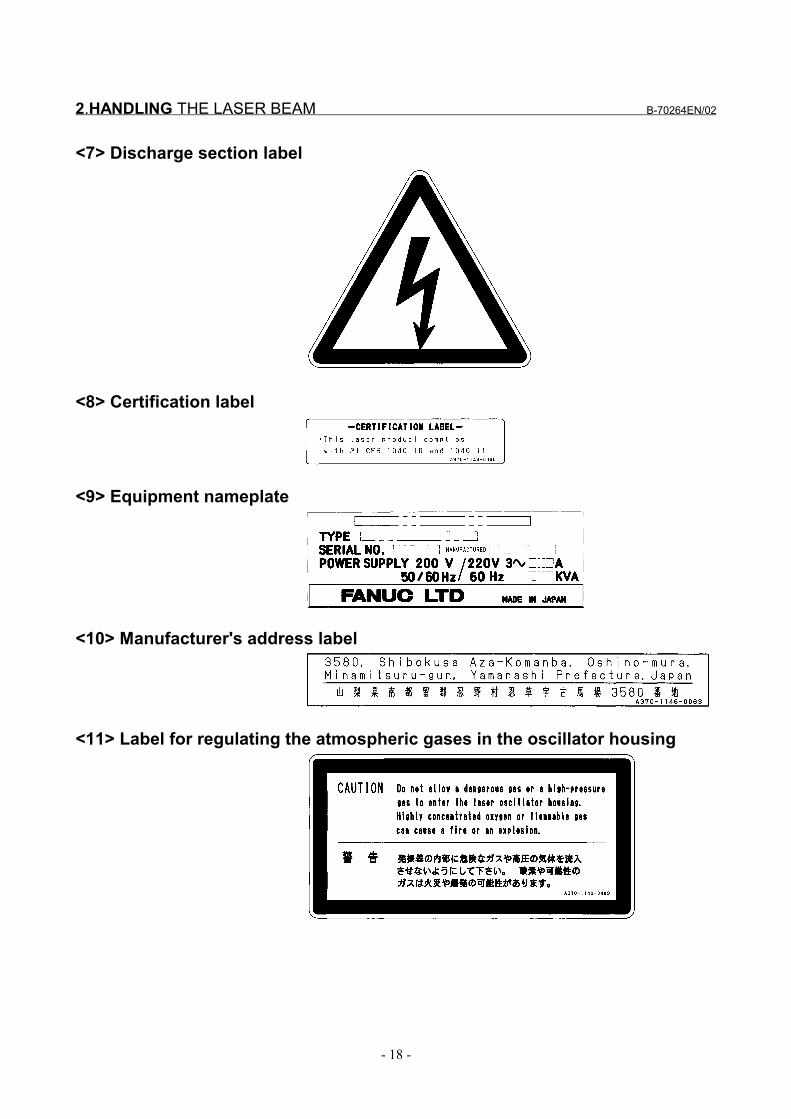
<7> Discharge section label
<8> Certification label
<9> Equipment nameplate
<10> Manufacturer's address label
<11> Label for regulating the atmospheric gases in the oscillator housing

B-70264EN/02 2.HANDLING THE LASER BEAM
- 19 -
<12> Cooling water and gas maintenance label
2.HANDLING THE LASER BEAM B-70264EN/02
- 20 -
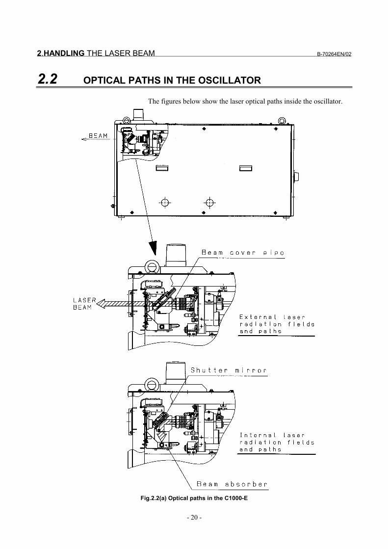
2.2 OPTICAL PATHS IN THE OSCILLATOR
The figures below show the laser optical paths inside the oscillator.
Fig.2.2(a) Optical paths in the C1000-E

B-70264EN/02 2.HANDLING THE LASER BEAM
- 21 -
Fig.2.2(b) Optical paths in the C2000-E
Fig.2.2(c) Optical paths in the C4000-E

2.HANDLING THE LASER BEAM B-70264EN/02
- 22 -
Fig.2.2(d) Optical paths in the C5000-E
Fig.2.2(e) Optical paths in the C6000-E

B-70264EN/02 3.INTERNAL STRUCTURE
- 23 -
3 INTERNAL STRUCTURE

3.INTERNAL STRUCTURE B-70264EN/02
- 24 -
3.1 OUTLINE
Fig. 3.1 shows an outline of the structure of the oscillator.
Fig.3.1 Outline of structure
(1) Laser resonatorThe resonator consists of an output mirror, a rear mirror, foldingmirrors, discharge tubes, a power sensor unit, etc. Severaldischarge tubes are connected in series using folding mirrors,with an output mirror and a rear mirror placed at the open endsof the discharge tubes, thus sealing the tubes. The resonator isfitted with a gas pipe connecting port through which laser gas isfed into the discharge tubes. A discharge from the electrodes ofthe discharge tubes energizes CO2 molecules, which emit light.This light is amplified by the stimulated emission that takesplace while the light travels back and forth between the outputmirror and the rear mirror. The resonator is capable ofconverting electrical energy to optical energy (10.6-µm single-wavelength laser beam).
(2) Energization power supplyThis is a high-frequency power supply of 2 MHz whose output iscontrolled by the CNC. It discharges the laser gas flows throughthe discharge tubes to energize CO2 molecules.

B-70264EN/02 3.INTERNAL STRUCTURE
- 25 -
(3) Laser gas circulating systemA gas circulating system is configured by connecting theresonator and the fan (turbo blower) with a circulating pipe.Laser gas runs through the discharge tubes at a speed of 200 m/sor higher. In this circulating system, a water-cooled heatexchanger, used to cool the high-temperature gas from thedischarge tubes, is provided at the inlet side of the turbo blower.At the outlet side of the turbo blower, another water-cooled heatexchanger is provided to dissipate the compression heat of theturbo blower.
(4) Pressure control unitTo ensure stable laser output, this controller controls the lasergas pressure of the laser gas circulating system with commandsissued from the CNC, while exhausting degraded laser gas.
(5) CNC interfaceThis is the interface of the laser oscillator for connecting toFANUC Series 16i-L. CNC commands that, control theoperation of the laser oscillator, such as start/stop and laseroutput, are input via this interface.
(6) HousingAn enclosure that houses the above components. The housing,consisting of metal panels, completely encloses the laseroscillator, thus protecting the operator from exposure to laserradiation and from high voltages. All panels are screw-fixed andcannot be removed without an appropriate tool.

3.INTERNAL STRUCTURE B-70264EN/02
- 26 -
3.2 INTERNAL STRUCTURE
This section describes the internal structure of the oscillator morespecifically. Fig.3.2(a) to (j) are internal structural drawing.
Fig.3.2(a) Internal structural drawing (C1000-E : front view)
Fig.3.2(b) Internal structural drawing (C1000-E : rear view)

B-70264EN/02 3.INTERNAL STRUCTURE
- 27 -
Fig.3.2(c) Internal structural drawing (C2000-E : front view)
Fig.3.2(d) Internal structural drawing (C2000-E : rear view)

3.INTERNAL STRUCTURE B-70264EN/02
- 28 -
Fig.3.2(e) Internal structural drawing (C4000-E : front view)
Fig.3.2(f) Internal structural drawing (C4000-E : rear view)

B-70264EN/02 3.INTERNAL STRUCTURE
- 29 -
Fig.3.2(g) Internal structural drawing (C5000-E : front view)
Fig.3.2(h) Internal structural drawing (C5000-E : rear view)

3.INTERNAL STRUCTURE B-70264EN/02
- 30 -
Fig.3.2(i) Internal structural drawing (C6000-E : front view)
Fig.3.2(j) Internal structural drawing (C6000-E : rear view)
(1) Output mirrorA transmitting/reflecting mirror which outputs the laser beamafter it has been amplified inside the resonator. The outputmirror consists of a ZnSe (zinc selenide) substrate with acurvature on the surface and coated with dielectric. ZnSe ishighly toxic. Be particularly careful, therefore, when handlingthe output mirror.
(2) Rear mirrorA reflecting mirror consisting of a Ge (germanium) substrate,coated with dielectric. The rear mirror is used to reflect the laserbeam within the resonator while transmitting part of the laserlight to the outside to obtain the monitor light for laser outputmeasurement.

B-70264EN/02 3.INTERNAL STRUCTURE
- 31 -
(3) Folding mirrorA mirror with an Si (silicon) substrate coated with dielectric toreflect the laser beam.It linearly polarizes the laser beam. A system equipped with anoptional antireflective mirror (ATFR) is available.The antireflective mirror consists of a copper substrate withcoating.
(4) Discharge tubeA pair of Ag (silver) electrodes are metallized on the surface of ahollow quartz glass pipe. A high-frequency discharge betweenthese electrodes injects electrical energy into the laser gas. Eachelectrode is coated with ceramic, preventing it from degradingand thus improving system reliability.
(5) Trigger electrodeThis electrode is capable of predischarging outside the laseroscillation area so that the laser output becomes completely zerowhen the beam is off.
(6) Power sensorAn optical sensor which detects the intensity of the laser beam,transmitted through the rear mirror, thus enabling monitoring ofthe laser output level.
(7) Oil mist decomposing elementThis element is capable of decomposing the organic matter thatgets into the laser gas circulating system, with photocatalyticeffect, using the ultraviolet rays generated from the dischargetubes.
(8) Laser power supplyThis power supply outputs high-frequency power (2 MHz)according to a specified output with commands from the CNCand supplies it to the discharge tubes via the matching box.
(9) Matching boxThe matching box contains a matching circuit, which ensuresthat power is effectively input to the discharge tubes.
(10) Turbo blowerThis fan circulates the laser gas in the gas circulating system athigh speed. It rotates at a high speed of 60,000 revolutions perminute (min-1).
(11) InverterThis inverter drives the turbo blower. It is responsible foracceleration/deceleration control and issuing alarms during startand stop of the blower.

3.INTERNAL STRUCTURE B-70264EN/02
- 32 -
(12) Turbo PCBThis PCB relays overheating and frequency reached signals ofthe turbo blower. In addition, it monitors the oil level of theturbo blower.
(13) Gas dust collection unitThis unit is a cyclone dust collector that removes dust that getsin the gas circulating system.
(14) Heat exchanger (inlet)Water-cooled heat exchanger used to cool the laser gas that hasbeen heated by discharge, before it is drawn into the turboblower.
(15) Heat exchanger (outlet)Water-cooled heat exchanger used to cool the laser gas that hasbeen heated by compression in the turbo blower, before beingforced into the discharge tubes.
(16) Gas control unit (C1000-E, C5000-E, C6000-E)This gas control unit constantly monitors the gas pressure ineach discharge tube and supplies fresh laser gas to the circulatingsystem to keep the pressure constant while exhausting degradedlaser gas. It also monitors the supply status of the laser gas,purge check for the circulating system, and other items and has afunction of adjusting the amount of flow of the gas to beexhausted. It provides the functions of both the C2000-E orC4000-E pressure control unit and the exhaust control unit.
(17) Pressure control unit (C2000-E, C4000-E)This gas control unit constantly monitors the gas pressure ineach discharge tube and supplies fresh laser gas to the circulatingsystem to keep the pressure constant while exhausting degradedlaser gas. It also monitors the supply status of the laser gas,purge check for the circulating system, and other items.
(18) Exhaust control unit (C2000-E, C4000-E)The exhaust control unit is capable of controlling the flow rate ofthe gas to be exhausted.
(19) Exhaust pumpThis pump is used to vacuum-exhaust laser gas from the gascirculating system such that its pressure falls to that used forlaser oscillation. In addition, it exhausts part of the degraded gasin the gas circulating system.
(20) Hour meterThe hour meter records the total number of hours that the laseroscillator has operated (how many hours the exhaust pump hasoperated) to indicate whether maintenance or inspection isnecessary.

B-70264EN/02 3.INTERNAL STRUCTURE
- 33 -
(21) ShutterThe shutter is normally closed to keep the laser beam inside, andcan be opened and closed with CNC commands. It is equippedwith a position sensor and a temperature sensor and constantlymonitors the open/close status and the shutter mirrortemperature.
(22) Beam absorberTo perform laser oscillation without emitting the laser beam tothe outside, the laser beam is reflected on the shutter mirror andguided into the beam absorber. The absorber, which is water-cooled, absorbs the laser beam. The absorber is equipped with atemperature sensor which allows the system to constantlymonitor the temperature of the absorber.
(23) Distribution unitThis unit distributes temperature-regulated external coolingwater to each unit inside the laser oscillator. The unit is equippedwith a flow sensor which allows the system to constantlymonitor the flow rate of the cooling water.
(24) Intermediate PCB BThis PCB relays signals collected into the shutter section, suchas those from the limit switch, absorber temperature sensor,power sensor, and condensation sensor, to the interface PCB.
(25) Input unitThis unit distributes the power supplied to the oscillator to eachunit in the laser oscillator. It also protects each unit fromovercurrents.
(26) Input unit control PCBThis PCB relays contactor open/close signals according to CNCcommands to the input unit.
(27) Interface PCBThis PCB communicates with the CNC via the FANUC I/OLINK (serial interface).
(28) Stabilized power supplyThis unit supplies DC power (24 VDC) to the interface PCB andvarious units.
(29) Dew sensorThis sensor is mounted to the output mirror holder to monitor theoutput mirror for condensation. It prevents faults in each unitfrom occurring due to condensation.

3.INTERNAL STRUCTURE B-70264EN/02
- 34 -
(30) Guide laser (red semiconductor laser)A diode laser is overlaid on the same optical axis as a guidebeam for checking the optical axis because the CO2 laser beam isinvisible to the unaided eye. The guide beam is emitted insynchronization with the mechanical shutter only when theshutter is closed. The guide laser can be used for roughlyadjusting the optical path of an external optical system and forobtaining a guide for the machining point.
(31) Beam folding unitThis unit extends the optical path length by folding back thelaser beam output from the output mirror in the oscillator andoutputting the beam from the outlet of the oscillator. It consistsof one circular polarization mirror and one zero shift mirror or oftwo zero shift mirrors. It is provided in an oscillator of shortoptical path length type; it is not provided in an oscillator of longoptical path length type.

B-70264EN/02 4.MAINTENANCE
- 35 -
4 MAINTENANCEIn laser oscillator, periodic inspection items have been reduced, andadjustments have been made easy. To keep the oscillator in asatisfactory operating condition over a long period, however, it isnecessary to carry out periodic maintenance (including dailyinspection) described in this chapter. The oscillator is designed tomaintain the same performance and reliability as it has when it isinstalled, provided that maintenance is carried out as prescribed.

4.MAINTENANCE B-70264EN/02
- 36 -
4.1 DAILY INSPECTION
Table 4.1 lists daily inspection items. Inspect the laser oscillatoraccording to this table. When parts (including oil) have been used fora prescribed period, replace them quickly.
Table 4.1 Daily inspection itemsItem Period Content and instruction
1 Residual laser gas DailyCheck the primary pressure as measured at the regulator on the laser gascylinder. If the primary pressure is 1MPa or lower, replace the gascylinder.
2 Exhaust pump oil WeeklyMake sure that the oil level is between L (lower limit) and H (higher limit). Ifthe level is L or below, replenish the oil by following the proceduredescribed in Subsection 4.3.2.
3 Exhaust pump oil leak WeeklyMake sure that no oil is leaking from the exhaust pump main body, drainvalve and their periphery. If oil is leaking, immediately replace the exhaustpump filter, because it is likely to have been clogged.
4 Turbo blower oil DailyMake sure that the oil level is between L (lower limit) and H (higher limit). Ifthe level is L or below, replenish the oil by following the proceduredescribed in Subsection 4.3.1.
5 Laser output WeeklyIf the laser output decreases within the oscillator, warning message No.4085 is issued. If this message appears, clean or replace the mirror in theoscillator quickly.
Daily
Check the discharge pressure of the chiller. If it is high, clean the waterpath.Wait for the water temperature to reach 20°C or greater before starting theoscillator.
6 Cooling water
Weekly
Check the amount of cooling water in the chiller and check forcontamination.If the amount of water is small, replenish the water. If the water iscontaminated, clean the water path and replace the water as appropriate.

B-70264EN/02 4.MAINTENANCE
- 37 -
4.2 PERIODIC MAINTENANCE
The laser oscillator contain consumables that must be replacedperiodically. Table 4.2(a) or (b) lists such consumables and therelated periodic maintenance work.Perform periodic maintenance as well as daily inspection described inSection 4.1 by using the listed periods as guidelines.Note, however, that the replacement and maintenance intervals are notguaranteed values.
Table 4.2(a) Periodic maintenance items and periods
Item Period of maintenance(operation hour) Remarks
1 Output mirror change Every 3,000 to 4,000 hours Change when the quality has degraded2 Rear mirror change Every 3,000 to 4,000 hours Change when the quality has degraded3 Folding mirror change Every 3,000 to 4,000 hours Change when the quality has degraded4 Exhaust pump oil change Every 1,500 hours Change when the exhaust power has degraded5 Exhaust pump filter change Every 3,000 hours Change when the exhaust power has degraded6 Exhaust pump overhaul Every 10,000 hours Change when the exhaust power has degraded7 Turbo blower oil change Every 1,000 hours Change when oil properties have changed8 Turbo blower overhaul Every 12,000 hours Conduct when the power has degraded, dust is
generated, or abnormal sound is generated9 Gas controller gas filter change Every 12,000 hours Change when a pressure failure occurs
10 Discharge tube O-ring change Every 6,000 hours Change when internal leakage occurs11 Gas pipe O-ring replacement Every 6,000 hours Change when internal leakage occurs12 Discharge tube cleaning Every 10,000 hours Conduct if quartz powder adheres to mirror13 Discharge tube change Every 30,000 hours Change when the quality has degraded14 Cooling water change Every 1,500 hours Change when cooling water properties have
changed15 Cleaning of interior of cooling
water systemEvery 3,000 hours Change when water pipe has clogged
16 Alarm lamp replacement Every 3,000 hours Change when the lamp fails to blink17 Oil mist decomposing element
changeEvery 10,000 hours Change when the power has degraded
18 Fan motor change Every 30,000 hours Subject to the operating environment.
Table 4.2(b) Mirror cleaning periodsUnit : hours
Model C1000-E C2000-E C4000-E C5000-E C6000-E
Cleaning of output and rear mirrors only None None(Note 1)
1,500 to 2,000(Note 1)
1,000 to 1,300
Cleaning of all internal mirrors 3,000 to 4,000
NOTE1 If the oil mist decomposing element and the gas dust collection unit are not
equipped, 1,500 to 2,000 hours for the C2000-E and 800 to 1,200 hours for theC4000-E.
2 The mirror cleaning periods are not guaranteed values. They are standard values inthe field.

4.MAINTENANCE B-70264EN/02
- 38 -
4.3 DETAILS OF MAINTENANCE
When opening the panels and doors during maintenance, keep thepower turned off. Before replacing oil, be sure to check that purgingis completed.
4.3.1 Turbo Blower Oil
(1) Check methodWith the laser oscillator at a rest, check to see if the oil level in theturbo blower is between graduations L and H. When the turbo bloweris running, it is impossible to check the amount of oil correctly.
Fig. 4.3.1(a) Appearance of turbo blower Fig. 4.3.1(b) Oil gage
(2) Replacement methoda) Before replacing the oil, be sure to stop the oscillator according
to the correct procedure and turn off the power. Remove thehexagonal-head screw from the oil inlet of the turbo blower witha 17 mm wrench. Be careful not to lose the O-ring on thehexagonal-head screw or contaminate it.
CAUTIONIf the oscillator is not stopped with the correctprocedure, the pressure in the vacuum system inthe oscillator becomes negative. Opening the oilinlet under such a condition lets air get in the turboblower. This flow of gas causes oil mist to get intothe vacuum system of the oscillator, resulting incontamination of internal mirrors.
b) Get a container for oil drain on hand, and put the tip of the draintube into the container.Turn the oil drain cock through 90 degrees, and the oil will startdraining.
c) After all the oil has been drained, close the oil drain cock bysetting it back in the initial place.

B-70264EN/02 4.MAINTENANCE
- 39 -
d) Remove the nozzle from the oil bottle, take off the inner lid, thenput the nozzle back on the bottle. Put the supplied tube into thenozzle, insert the tube into the oil inlet, pour oil being careful tocause no foreign matters to get into oil.Pour oil while checking the oil level from the oil level windowuntil the oil level reaches the three-quarter position from Lbetween L and H. Either superfluous or insufficient oil can be acause of trouble.
e) Lightly wipe the area around the oil inlet, hexagonal-head screwon the oil inlet, and O-ring with a clean cloth or paper, thencheck that there are no foreign matters. Foreign matters gettinginto oil may cause a turbo blower fault. Check that the O-ring isfit to the hexagonal-head screw on the oil inlet, then tighten thescrew (recommended torque: 800N⋅cm)
CAUTIONIf the O-ring at the inlet is damaged, gas leak willresult.
f) If oil has spilled over, wipe it up.g) After replacing the oil for the turbo blower, be sure to conduct
automatic aging as described in Subsection 4.3.5.
CAUTIONIf you do not conduct automatic aging afterreplacing the oil for the turbo blower, correctdischarge is not possible, which can become acause of trouble.
h) If there is oil left over, put the inner lid back on the bottle, andkeep the bottle in a dark, cool place.
CAUTIONOnce you open a new oil package, you should useit within six months. Even for an oil package notopened, you should use it within one year. Neveruse old oil whose validity has expired. Using suchoil can cause a failure in the turbo blower.

4.MAINTENANCE B-70264EN/02
- 40 -
4.3.2 Exhaust Pump Oil
(1) Check methodWatch the oil gauge, and check that the oil level is betweengraduations Low and High. Also check whether the oil is dark.If the oil level is below L, add oil to the turbo blower or replace theoil in it. If the oil level is above H, drain until the oil level becomesbelow H.
Fig.4.3.2(a) Front view of exhaust pump Fig.4.3.2(b) Enlarged view of oil gage
(2) Replacement methoda) Stop the laser oscillator with the correct procedure, and turn the
power off.b) Remove the oil inlet plug. There is an O-ring on it. Be careful
not to damage it. A missing or damaged O-ring can lower theexhaust capacity of the pump.
c) Insert the drain tube into a drain oil vessel.d) Open the drain cock.e) After the oil has been drained up, close the cock.f) Pour new oil into the oil inlet, while checking the oil gage.g) Attach the oil inlet plug.

B-70264EN/02 4.MAINTENANCE
- 41 -
4.3.3 Exhaust Pump Filter
(1) Replacement methodWhen the operation time reaches 3000 hours or the exhaust capacitygets lowered, replace the filter. A clogged filter may cause a whitishsmoke of oil mist to come out of the pump or lower the exhaustcapacity.
a) Stop the laser oscillator with the correct procedure, and turn thepower off. The pump is hot immediately after it has stopped.Start the work after the pump has cooled down.
b) Remove the black screw from the exhaust pump unit, thenremove the filter cover and O-ring.
c) Remove the spring and washer.d) Pull out the exhaust filter element.e) Check the mounting orientation of a new exhaust filter element,
then insert the filter. A filter element mounted improperly maycause oil mist (whitish smoke) to come out of the gas outlet.Therefore, check again that the filter is mounted properly.

4.MAINTENANCE B-70264EN/02
- 42 -
4.3.4 Checking Operation Times
The cumulative operation time of each component is displayed on themaintenance screen of the CNC. Use it for periodic maintenance.
(1) MethodPress the "Setting" operation key on the CNC.Then, press the soft keys at the bottom of the CNC screen as follows:
(2) Display screenPressing the [PW.OFS] soft key causes the operation time displayscreen to be displayed. If you enter a limit time in a set time field inadvance, the operation time display will turn red when the operationtime exceeds 90% of the set time. If it exceeds the set time, theoperation time display in red reverse video.The set time and the operation time are in 0.1-hour units.To switch pages, use the "PAGE ↑" and PAGE ↓" keys on the MDIpanel.
(3) Methods of entering a set time and resetting an operation timeIn this normal state, this screen prohibits the entry of data so that datasuch as operation times is not deleted by mistake.To enter data, first set bit 1 of parameter No. 15610 (MDS) to 1.To enter a set time or reset an operation time, position the cursor onthe desired field, using the arrow keys as appropriate, enter a settingfrom the MDI unit, and press the <INPUT> key.No special soft keys such as all clear are not available. To reset anoperation time, set 0.
POWER SET DATA
STATUS MAINT.
PW.OFS ACT.TM ALARM
Operation timedisplay

B-70264EN/02 4.MAINTENANCE
- 43 -
(4) Parameter setting (a) If the screen is not displayed even after screen manipulation
Check the settings of the following parameters and change them asappropriate.i) Press the <SYSTEM> operation key on the CNC to select the
parameter screen.ii) Check that bit 0 of parameter No. 15160 (MNT) is set to "1".iii) If it is not set to "1", set bit 0 of parameter No. 15160 (MNT) to
"1" referring to "Setting Parameters" in Chapter 6.iv) Return "PARAMETER WRITE" to "DISABLE".
#7 #6 #5 #4 #3 #2 #1 #0
15160 MDS MNT
MNT0 : Does not display the laser maintenance screen.1 : Displays the laser maintenance screen.
MDS0 : Disables data input on the laser maintenance screen.1 : Enables data input on the laser maintenance screen.
(b) Resetting an operation timeAfter an operation time has reached the corresponding set time andyou have conducted maintenance, you may want to reset the operationtime to 0. To do this, follow the procedure below.i) Set bit 1 of parameter No. 15160 (MDS) to "1" referring to
"Setting Parameters" in Chapter 6.ii) Display the component operation time display screen, move the
cursor to the desired operation time field, and enter 0. Theoperating time is reset.
iii) After resetting, return bit 1 of parameter No.15160 to "0" andreturn "PARAMETER WRITE" to "DISABLE".

4.MAINTENANCE B-70264EN/02
- 44 -
4.3.5 Automatic Aging
If you open the laser gas circulating system to the atmosphere afterreplacing the turbo oil, for example, you can perform discharge agingby using the automatic aging function. The operating method isdescribed below.
(1) Display the parameter screen and check that bit 6 of parameterNo. 15008 (EGE) is set to "1".
#7 #6 #5 #4 #3 #2 #1 #0
15008 EGE
EGE Automatic aging function is:1 : Enabled.0 : Disabled.
(2) If the parameter has been set, turn on the oscillator start switch(RUN), and when the discharge ready state (LRDY) isestablished, set parameter No. 15334 (number of times aging isto be performed) to "2" referring to "Setting Parameters" inChapter 6.
(3) Set the parameter and then turn on the discharge start switch(HVON), and aging is executed the specified number of times.After the end, the oscillation ready state is established.
(4) If bit 6 of parameter No. 15008 (EGE) is not set to "1", set it to"1" referring to "Setting Parameters" in Chapter 6. Check thesettings of parameters Nos. 15326 to 15331 and Nos. 15320 to15325 and then follow steps (2) and (3).
ModelPRMNo. Description C1000-E C2000-E C4000-E C5000-E C6000-E
15326 Power command when aging is performed with theautomatic aging
700 1000 2500 3500 4000
15327 Oscillation frequency command for aging 100 100 100 100 10015328 Pulse duty cycle command for aging 50 50 50 30 3015329 Time required to perform aging once 900 900 900 900 90015330 Gas pressure setting (50 Hz) for aging 500 560 630 740 52015331 Gas pressure setting (60 Hz) for aging 500 560 630 740 52015320 Command power for power compensation 1000 2000 4000 5000 600015321 Oscillation frequency command for power
compensation100 100 100 100 100
15322 Pulse duty cycle command for powercompensation
100 100 100 100 100
15323 Command time for power compensation 180 180 300 300 30015324 Gas pressure setting for power compensation
(50Hz)600 660 730 840 620
15325 Gas pressure setting for power compensation(60Hz)
600 660 730 840 620

B-70264EN/02 4.MAINTENANCE
- 45 -
4.4 MAINTENANCE PARTS LIST
The following table lists maintenance parts.
Quantity usedName SpecificationC1000-E C2000-E C4000-E C5000-E C6000-E
1 Exhaust pump filter A98L-0001-0911 1 1 1 1 12 Exhaust pump oil A98L-0040-0093#1.0L6 (3.6L) (3.6L) (3.6L) (3.6L) (3.6L)3 Turbo blower oil A04B-0800-K326 (1/3) (1/3) (1/3) (2/3) (2/3)
4 O-ringTurbo blower oil inlet JB-OR4D-P10A 1 1 1 2 2

5.ALARMS B-70264EN/02
- 46 -
5 ALARMS

B-70264EN/02 5.ALARMS
- 47 -
5.1 CHECKING THE ALARM OCCURRENCE STATUS
After identifying the following items, call the service center.(1) General information on a fault
(a) Date and time of occurrence(b) State of operation(c) Timing of a fault (alarm)(d) Alarm number(e) How often the fault occurs
(2) Other information(a) Oscillator and CNC unit names(b) Oscillator serial number(c) Machine tool builder name, machine type(d) Software series and edition indicated on the CRT screen
when power is turned on(e) Settings of related parameters(f) Related data (diagnosis screen)

5.ALARMS B-70264EN/02
- 48 -
5.2 LIST OF ALARMS
The following table lists the alarms attributable to the laser oscillator.Number Message Alarm handling level
4061 A/D CONVERTER–1 Up to a purge4062 A/D CONVERTER–2 Up to a purge4063 RF POWER SUPPLY / LASER GAS Up to LRDY4065 SHUTTER ACTION Up to LRDY4066 DISCHARGING Up to LRDY4067 LASER CABINET OH Up to a purge
4068 BEAM REFLECTION In the LSTR state,shutter closed, beam OFF
4069 LASER IF PCB Up to a purge4070 CHILLER NOT READY Up to a purge
4071 ASSIST GAS NOT READY In the LSTR state,shutter closed, beam OFF
4072 CHILL FLOW Up to a purge4073 LASER GAS PRES. Up to a purge4074 ROOTS BLOWER TEMP. Up to a purge4075 CHILL TEMP. Up to a purge4076 LASER POWER DOWN Up to a purge4077 ABSORBER TEMP. Up to a purge4078 LASER TUBE PRES. Up to a purge4079 PUSH RESET KEY Up to LRDY4080 LASER TUBE EXHAUST Up to a purge4081 GAS PRES. CONTROL Up to a purge4082 TUBE PRES. SENSOR Up to a purge
4083 SHUTTER NOT OPEN In the LSTR state,shutter closed, beam OFF
4085 MIRROR CLEANING Warning issuedTo be canceled with reset
4087 SHUTTER OH Up to LRDY4088 LASER VOLTAGE DOWN Up to a purge4089 ASSIST GAS NO SELECT4090 LASER NOT GENERATE
In the LSTR state,shutter closed, beam OFF
4094 VANE PUMP Up to a purge4099 GAS PRES. NOT REACH Up to a purge4100 INVERTER 1 Up to a purge4101 OUT OF FREQUENCY 1 Up to a purge4105 TURBO TEMP. 1 Up to a purge4106 BLOWER OIL SHORTAGE Up to a purge4107 MIRROR NOT INSTALLED Up to LRDY4132 PARAMETER WAS CHANGED Up to LRDY

B-70264EN/02 5.ALARMS
- 49 -
5.3 ALARM DETAILS
Alarm numbers, as well as DGN and PRM Nos., are those of theFS16i-L.Check the related parameters and the information on the diagnosisscreen.
ALM No.4061A/D CONVERTER–1Alarm output condition
This alarm is issued when the A/D converter 1 on the IF PCB does notreturn the conversion completion signal in the specified time after thestart of conversion. This A/D converter is designed to read gas pressureand power data.
Related dataDGN.981 Data when A/D1 conversion becomes abnormal.
ALM No.4062A/D CONVERTER–2Alarm output condition
This alarm is issued when the A/D converter 2 on the IF PCB does notreturn the conversion completion signal in the specified time after thestart of conversion. This A/D converter is designed to read dischargetube voltage and current data.
Related dataDGN.982 Data when A/D2 conversion becomes abnormal.
ALM No.4063RF POWER SUPPLY / LASER GAS
This message appears when the laser power supply unit becomesabnormal or performs protective operation. The power supplyunit performs protective operation even if an error occurs inother than the power supply unit itself. This alarm will recurafter replacement of the power supply alone without eliminatingthe root cause.
Alarm output conditionThis alarm is issued if, after the LRDY state is established in thesequence, an alarm signal is sent from the power supply unit, and any ofthe power supply operation status signal becomes "0". Note that a powersupply that is not set with parameter No. 15025 or 15027 is not checked.
Related parametersPRM.15025,15027 Power supply selection
Related dataDGN.966 Power supply unit operation statusDGN.970 Power supply unit selection signalDGN.974 Power supply unit alarm display

5.ALARMS B-70264EN/02
- 50 -
ALM No.4065SHUTTER ACTIONAlarm output condition
This alarm is issued if, after the LRDY state is established in thesequence, the shutter open command does not match the shutter state.When the shutter open signal SHOP is "1", the system is considerednormal with the shutter state signals SHON=1 and SHOF=0.When the shutter open signal SHOP is "0", the system is considerednormal if the shutter state signals SHON=0 and SHOF=1.Otherwise, the alarm is issued. When SHOP changes, however, thealarm monitor is masked for the time set in parameter No. 15152(default: 3 seconds).
Related dataDGN.961 #4 SHON Shutter open stateDGN.961 #5 SHOF Shutter closed stateDGN.973 #0 SHOP Shutter open commandF200 #4 SHTONL Shutter ON signalF200 #3 SHTOFL Shutter OFF signal
ALM No.4066DISCHARGING
After the discharge start (HV ON) signal is turned on, thedischarge starts. At this time, this alarm is issued if at least onedischarge tube does not discharge and causes high voltage.
Alarm output conditionWhen the HVON signal is turned on, the discharge tubes are started upto the maximum specified with the bias command in six seconds. Then,after the time set with parameter No.15222 has elapsed, the voltage ofeach discharge tube is compared with the setting of parameterNo.15221. This alarm is issued if the voltage of at least one dischargetube exceeds the setting of the parameter.
Related parametersPRM.15220 Maximum bias command valuePRM.15221 Discharge start check voltagePRM.15222 Discharge wait timePRM.15223 Bias command
Related dataDGN.909-914 Discharge tube voltage and currentG222 #7 HVON Discharge start signal

B-70264EN/02 5.ALARMS
- 51 -
ALM No.4067LASER CABINET OH (detected by the C2000-E only)
The temperature of the input side of the electrode cooling fan ismonitored and sends alarm when it exceeds 60°C.When the temperature decreases below the prescribed value, thealarm state can be solved by resetting. Before that, it cannot besolved.
Alarm output conditionThis alarm is issued if the "temperature in the cabinet" signal becomes"0" after the start of the oscillator and immediately before the completionof purging.
Related dataDGN.961 #1 *CAT Temperature in the cabinet
ALM No.4068BEAM REFLECTION
This alarm is issued, if a workpiece reflects laser beam morethan the rating to the laser oscillator. This can happen when thelaser beam is used to drill, cut, or weld materials (such as copper,brass, and aluminum) having a high reflectivity to the laser beam(10.6 µm).
Alarm output conditionThis alarm is issued when the actual laser output is in one of thefollowing conditions at the time of beam output:(1) The actual laser output is higher than the average command power
(power × duty) by more than the value set in parameter No. 15265.(2) The actual laser output exceeds the value set in parameter No.
15266.The actual laser output is not monitored for five seconds after the beamis turned on or the output is changed.
Related parametersPRM.15215 Power input compensation coefficientPRM.15265 Allowable output increase valuePRM.15266 Output limit
Related dataDGN.906 Actual output
ALM No.4069LASER IF PCB
This alarm appears when there occurs the anomaly in thestabilized power unit voltage +5, ±15, +24V of IF PCB for NCinterface.
Alarm output conditionThe enable signal in the IF in the IF PCB becomes "0" and this alarm isissued when an error occurs in the stabilized power unit voltage (+5V,±15V, +24V) after the start of the oscillator and immediately before thecompletion of purging.
Related dataDGN.960#0 *ENB Enable signal in the interface

5.ALARMS B-70264EN/02
- 52 -
ALM No. 4070CHILLER NOT READY
Turning on the oscillator start switch causes the system to outputa chiller start request signal to the machine. After a chiller readysignal is received from the chiller unit, this signal is monitored,and if this signal is interrupted, this alarm is issued.
Alarm output conditionMonitoring starts in four seconds after the output of a chiller start signal,and monitoring ends when the oscillator start switch is turned off.If the chiller ready signal CLRDY (G221#6) becomes 0 duringmonitoring, this alarm is issued.
Related dataG221 #6 CLRDY Chiller ready signalF221 #4 CLON Chiller start request signal
ALM No.4071ASSIST GAS NOT READY
When starting machining, the CNC monitors the assist gas readysignal from the assist gas supply unit in the machine. If thissignal is interrupted, this alarm is issued. This alarm is issuedalso when in G32PαQβ, α is not 0 to 3, or β is not 1 to 7 duringprogram execution.
Alarm output conditionThis alarm is issued when the assist gas ready signal (G221#7)becomes 0 during the assist gas output command.
Related dataG221 #7 AGRDY Assist gas ready signalG222 #5 AGST Assist gas start signalF222 #0-#2 AG1-3 Assist gas selection signal
ALM No.4072CHILL FLOW
This alarm appears when the water shortage takes place.Alarm output condition
This alarm is issued if the cooling water amount signal becomes "0" fromthe time the oscillator start switch is turned on until it is turned off and thesignal remains "0" when re-checked in five minutes.
Related dataDGN.961#0 *MVW Cooling water amount

B-70264EN/02 5.ALARMS
- 53 -
ALM No.4073LASER GAS PRES.
The pressure of the laser gas supplied to the laser oscillator ismonitored.This alarm is issued, if this pressure becomes lower than thepermissible level.
Alarm output condition1) This alarm is issued if the laser gas supply pressure sensor signal
MGP becomes "0" from the time the oscillator start switch is turnedon until it is turned off.The alarm monitor is masked while the purge valve is open and forfive seconds after the valve is closed, and while the exhaust valve ofthe external piping is open and for five seconds after the valve isclosed.
2) This alarm is issued when purge operation is not completed in threeminutes after the start of purge operation.
3) When a laser gas mixing device is provided, this alarm is issued ifthe tank supply pressure signal TEM becomes 0.
Related parametersPRM.15009 #7 TEM Tank supply pressure (automatically rewritten with
the state signal from the mixer)Related data
DGN.960 #5 *MGP Laser gas supply pressure sensorDGN.972 #0 PUG Purge valve
ALM No.4074ROOTS BLOWER TEMP.
For oscillators with a turbo blower attached, this alarm is notissued.
Related parametersPRM.15003 #5 TON Whether a turbo blower is attached (must be set to
"1")
ALM No.4075CHILL TEMP.
A condensation sensor is mounted to the output mirror holder inthe oscillator. This alarm occurs when the sensor detectscondensation. After this alarm occurs, the alarm status cannot bereset until the condensation status is released.
Alarm output conditionThis alarm is issued if the condensation signal becomes "0" from thetime the oscillator start switch is turned on until it is turned off.
Related dataDGN.961#2 *WT1 Condensation

5.ALARMS B-70264EN/02
- 54 -
ALM No.4076LASER POWER DOWN
This alarm is issued if the monitored laser output is lower thanthe specified laser output by at least the allowable value.
Alarm output conditionThis alarm is issued when the actual laser output level is lower than theaverage command power (power x duty) by more than the value set inparameter No. 15271. Monitoring, however, is not performed for threeseconds after the beam is turned or after the output is changed.
Related parametersPRM.15271 Allowable output drop value
Related dataDGN.906 Actual output
ALM No.4077ABSORBER TEMP.
This alarm is issued if the temperature absorber exceeds theallowable value. In the usual operation, this beam absorber isirradiated by the rated output only during the laser outputcompensation conducted after the start of the oscillator.
Alarm output conditionThis alarm is issued if the absorber temperature signal becomes "0"after the start of the oscillator and immediately before the completion ofpurging.
Related dataDGN.961#7 *ABT Absorber temperature
ALM No.4078LASER TUBE PRES.
The gas pressure is monitored after the discharge start readycondition (LRDY) is established. This alarm is issued, if themonitored gas pressure deviates by ±100 (1330Pa) from the setgas pressure.
Alarm output conditionThis alarm is issued if the actual gas pressure falls out of the set gaspressure ±100 after LRDY is established. The pressure is not monitoredfrom the time the HV ON signal is turned off until LRDY is established.
Related dataDGN.905 Actual gas pressure

B-70264EN/02 5.ALARMS
- 55 -
ALM No.4079PUSH RESET KEY
If the emergency stop button is pressed after the discharge startready condition (LRDY) is set up, the shutter is closed,discharge stops, and the LRDY condition is resumed, then thisalarm is issued. To reset the alarm, remove the cause of trouble,release the emergency stop button, and press the reset key on theoperator's panel.
Alarm output conditionThis alarm is issued if an emergency stop occurs after LRDY isestablished in the sequence.
Related dataDGN.960#1 *ESAL Emergency stop processing signal
ALM No.4080LASER TUBE EXHAUST
When the oscillator start switch is turned on, the exhaust pumpstarts evacuating the gas in the circulating system to place theoscillator in the low-pressure state. At this time, this alarm isissued if the pressure does not reach the prescribed vacuumpressure when the specified time (default: 10 minutes) haselapsed after the start of exhaust.
Alarm output conditionTurning the oscillator start switch on causes exhaust to start. This alarmis issued if the laser gas pressure does not reach the setting ofparameter No. 15240 when the time set in parameter No.15259 haselapsed.
Related parametersPRM.15240 Evacuation completion negative pressurePRM.15259 RUN-ON exhaust time
Related dataDGN.905 Actual gas pressure
ALM No.4081GAS PRES. CONTROL
The pressure is monitored 45 seconds after the start of gaspressure control. This alarm is issued if the pressure falls out ofthe prescribed range.
Alarm output conditionThis alarm is issued when the actual gas pressure is not within ±20 ofthe parameter setting (parameter No. 15241) after 45 seconds havepassed since the start of gas pressure control.
Related parametersPRM.15241 Gas pressure at the start of discharge
Related dataDGN.905 Actual gas pressure

5.ALARMS B-70264EN/02
- 56 -
ALM No.4082TUBE PRES. SENSOR
This alarm appears when the signal of the pressure sensor usedfor pressure control detector vanishes.
Alarm output conditionThis alarm is issued if the actual gas pressure is detected to be zero orless twice in a row at 16-msec intervals from the time the oscillator startswitch is turned on until it is turned off.
Related dataDGN.905 Actual gas pressure
ALM No.4085MIRROR CLEANING
This alarm appears when the laser output power decreases andtakes an abnormally higher calibration coefficient.This monitoring is executed at the start of the oscillator for thepurpose of checking for decreases in output due to contaminationand degradation of optical components.
Alarm output conditionThis alarm is issued when the power compensation coefficient exceedsthe power compensation limit during execution of power compensation.Power compensation coefficient = (Pc/Pa) × 1024Pc : Parameter No. 15200 or 15201Pa : Actual laser output
Related parametersPRM.15200 Power compensation command output for a half of the
discharge tubesPRM.15201 Power compensation command output for all discharge
tubesPRM.15203 Power compensation limitPRM.15204 Power compensation coefficient
ALM No.4087SHUTTER OH
This alarm is issued when the temperature of the shutter mirrorexceeds a preset maximum.
Alarm output conditionThis alarm is issued if the shutter temperature signal becomes "0" afterLRDY is established in the sequence.
Related parametersDGN.961#6 *SHT Shutter temperature

B-70264EN/02 5.ALARMS
- 57 -
ALM No.4088LASER VOLTAGE DOWN
This alarm is issued, if the voltage applied to the discharge tubedrops largely.
Alarm output condition1) Immediately before the oscillation ready state (LSTR) is established,
the RF voltage of the power supply with the smallest number in theselected discharge tubes is compared with the discharge tubevoltage in normal condition (parameter No. 15270). This alarm isissued if the voltage has dropped by at least the allowable dischargetube voltage drop. If the drop is less than the allowable drop, the RFvalue at this time is stored in parameter No. 15270 as the dischargetube voltage in normal condition.
2) During power compensation or in LSTR in which external powercontrol is not in progress, the RF voltage is compared with thedischarge tube voltage in normal condition (parameter No.15270). Ifthe voltage has dropped by at least the allowable discharge tubevoltage drop, another comparison is made in one second. Thisalarm is issued if the state remains unchanged.
Related parametersPRM.15270 Discharge tube voltage in normal conditionPRM.15272 Allowable discharge tube voltage drop
Related dataDGN.909-924 Discharge tube voltage and current
ALM No.4089ASSIST GAS NO SELECT
This alarm is issued when no assist gas is output during beamoutput.
Alarm output conditionThis alarm is issued, if an attempt is made to radiate a laser beam, whenno assist gas is selected, or an assist gas condition is not set up.
Related dataF222#0 to #2 Assist gas selection signal
ALM No.4090LASER NOT GENERATE
This alarm is issued if an attempt is made to radiate a laser beamwhen the laser is not in the oscillation ready (LSTR) state.
Alarm output conditionThis alarm is issued if the oscillation ready (LSTR) state is notestablished during beam output.
Related dataF221#6 Oscillation in-progress signal

5.ALARMS B-70264EN/02
- 58 -
ALM No.4094VANE PUMP
This alarm occurs when the thermal switch of the magneticcontactor for the exhaust pump is tripped.
Alarm output conditionThis alarm is issued if the exhaust pump alarm RPAL becomes "0" afterthe start of the oscillator and immediately before the completion ofpurging.
Related dataDGN.972 RPA Exhaust pump startDGN.961#3 *RPAL Exhaust pump alarm
ALM No.4099GAS PRES. NOT REACH
After the discharge start signal (HV ON) is turned on, the gaspressure in the discharge tube is compared with the setting of thepressure in the tube during oscillation. This alarm is issued if thepressure does not reach the tolerable amount by which the targetpressure is not reached.
Alarm output conditionWhen the integral value of gas pressure control is preset and thepressure is increased from the from the gas pressure at the start ofdischarge to the gas pressure during oscillation, this alarm is issued ifthe actual gas pressure has not increased to the value equal to thesetting of the pressure in the tube during oscillation (parameter No.15242 or 15243) minus the setting of parameter No.15248 in 15seconds after the gas pressure target reaches the gas pressure duringoscillation.
Related parametersPRM.15001#3 Specifies whether to preset the integral value of gas
pressure control.PRM.15242,15243 Setting of the pressure in the tube during oscillationPRM 15247 Pressure control integrator element preset valuePRM.15248 Tolerable amount by which the target gas pressure
is not reachedRelated data
DGN.905 Pressure in the discharge tube
ALM No.4100INVERTER 1
If the inverter used to power the turbo blower is abnormal, thisalarm is issued.When this alarm is issued, check that the alarm LED on the LEDindicator section of the inverter is lit. At this time, do not turn offthe power to the inverter because the alarm will be reset if thepower is turned off.
Alarm output conditionThis alarm is issued if the inverter alarm signal becomes "0" after thestart of the oscillator and immediately before the completion of purging.
Related dataDGN.962#0 *IAL1 Inverter alarm
B-70264EN/02 5.ALARMS
- 59 -
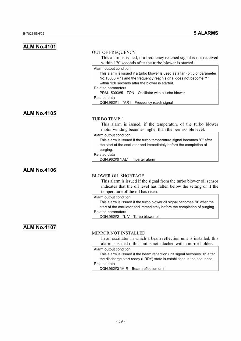
ALM No.4101OUT OF FREQUENCY 1
This alarm is issued, if a frequency reached signal is not receivedwithin 120 seconds after the turbo blower is started.
Alarm output conditionThis alarm is issued if a turbo blower is used as a fan (bit 5 of parameterNo.15003 = 1) and the frequency reach signal does not become "1"within 120 seconds after the blower is started.
Related parametersPRM.15003#5 TON Oscillator with a turbo blower
Related dataDGN.962#1 *AR1 Frequency reach signal
ALM No.4105TURBO TEMP. 1
This alarm is issued, if the temperature of the turbo blowermotor winding becomes higher than the permissible level.
Alarm output conditionThis alarm is issued if the turbo temperature signal becomes "0" afterthe start of the oscillator and immediately before the completion ofpurging.
Related dataDGN.962#0 *IAL1 Inverter alarm
ALM No.4106BLOWER OIL SHORTAGE
This alarm is issued if the signal from the turbo blower oil sensorindicates that the oil level has fallen below the setting or if thetemperature of the oil has risen.
Alarm output conditionThis alarm is issued if the turbo blower oil signal becomes "0" after thestart of the oscillator and immediately before the completion of purging.
Related parametersDGN.962#2 *L-V Turbo blower oil
ALM No.4107MIRROR NOT INSTALLED
In an oscillator in which a beam reflection unit is installed, thisalarm is issued if this unit is not attached with a mirror holder.
Alarm output conditionThis alarm is issued if the beam reflection unit signal becomes "0" afterthe discharge start ready (LRDY) state is established in the sequence.
Related dataDGN.962#3 *M-R Beam reflection unit

5.ALARMS B-70264EN/02
- 60 -
ALM No.4132PARAMETER WAS CHANGED
This alarm is issued if a parameter is changed.Alarm output condition
This alarm is issued if parameter No. 15223, 15242, or 15243 ischanged after the discharge start ready (LRDY) state is established.
Related dataPRM.15223 Specified discharge bias valuePRM.15242,15243 Setting of the pressure in the tube during oscillation
Before turning on the discharge start signal (HV ON), press theRESET key to release this alarm.

B-70264EN/02 5.ALARMS
- 61 -
5.4 DISPLAY ITEMS ON THE DIAGNOSIS SCREEN
If a fault occurs, it is necessary to determine in which of the CNC,machine, and laser oscillator the fault occurred. In cases other thanfaults in which the machine seems to be faulty because it does notoperate due to an external signal waiting state, it is useful if theinternal state of the CNC, the states of the interfaces of the PMC andthe laser oscillator, and other information can be confirmed easily.This section describes the data display items of the self-diagnosisfunction of the CNC that indicate the states of the faults that canoccur inside the laser oscillator. For a description of the data displayitems of the self-diagnosis function that are related to the states of thefaults that can occur inside the CNC, PMC, and machine, refer to theFANUC Series 16i-L Maintenance Manual.
5.4.1 Screen Display Operation
Operate screen display referring to the procedure for displaying thescreen in Chapter 6.
5.4.2 Signal Display on CNC-PMC (Machine Operator's Panel)
[CNC←←←←PMC status display]#7 #6 #5 #4 #3 #2 #1 #0
G220 *DU16 *DU8 *DU4 *DU2 *DU1
*DU1 to *DU16 Duty override signals
#7 #6 #5 #4 #3 #2 #1 #0
G221 AGRDY CLRDY
AGRDY Assist gas prepared signalCLRDY Chiller prepared signal
#7 #6 #5 #4 #3 #2 #1 #0
G222 HVON RUN AGST BEMON SHTON SCLON *BEMLC *SHTLC
HVON Discharge start signalRUN Oscillator start signal
AGST Assist gas start signalBEMON Beam on signalSHTON Shutter open signalSCLON Guide light on signal
*BEMLC Beam lock signal*SHTLC Shutter lock signal

5.ALARMS B-70264EN/02
- 62 -
#7 #6 #5 #4 #3 #2 #1 #0
G223 POV7 POV6 POV5 POV4 POV3 POV2 POV1 POV0
POV7 to POV0 Power override signals
#7 #6 #5 #4 #3 #2 #1 #0
G224 LCKON
LCKON Leak check signal
#7 #6 #5 #4 #3 #2 #1 #0
G228 *FOV7 *FOV6 *FOV5 *FOV4 *FOV3 *FOV2 *FOV1 *FOV0
*FOV7 to *FOV0 Frequency override signal
[CNC→→→→PMC status display]#7 #6 #5 #4 #3 #2 #1 #0
F220 MWRM SHTONL SHTOFL
MWRM Output decrease alarm signalSHTONL Shutter on state signalSHTOFL Shutter off state signal
#7 #6 #5 #4 #3 #2 #1 #0
F221 BEAM LSTR RFHV CLON WAIT PURGE LRDY LARM
BEAM Beam on signalLSTR Oscillation ready signalRFHV Base in-discharging signalCLON Chiller start request signalWAIT Gas pressure in-controlling signal
PURGE Purge completed signalLRDY Discharge start prepared signalLARM Laser alarm signal
#7 #6 #5 #4 #3 #2 #1 #0
F222 CW PULSE AG3 AG2 AG1
CW Continuous wave mode state output signalPULSE Pulse mode state output signal
AG1 to AG3 Assist gas select signals
#7 #6 #5 #4 #3 #2 #1 #0
F224 AVCL LCKMD
AVCL Valve close signal0 : Normal state1 : All valve closed state

B-70264EN/02 5.ALARMS
- 63 -
LCKMD Leak check mode signal0 : Normal sequence1 : Leak check mode
#7 #6 #5 #4 #3 #2 #1 #0
F226 AGING
AGING Automatic aging in progress signal
5.4.3 Laser Oscillator Status Display
900 LASER POWER COMMAND
Displays a value specified in a laser output power command and sentto the D/A converter.
901 LASER BIAS COMMAND
Displays a value specified in a base discharge command and sent tothe D/A converter.
902 PULSE ON TIME
Displays the ON time period of an output power command pulsesignal.
903 PULSE OFF TIME
Displays the OFF time period of an output power command pulsesignal.
904 GAS PRES. CONTROL
Displays a value specified in a pressure command for the pressurecontroller that controls pressure inside the discharge tube, and sent tothe DA converter.
905 LASER TUBE PRES.
Displays the pressure inside the discharge tube.Display range : 0 to 900
906 LASER POWER
Displays monitored laser output power values.Unit : W

5.ALARMS B-70264EN/02
- 64 -
908 LASER SEQUENCE
No. Contents No. Contents10 Purge completion state 23 Wait for change to discharge
start gas pressure12 Purge being executed 26 Start of discharge in progress14 75-s wait 27 Base discharge set waiting state16 Exhaust pump activated 28 Power compensation in
progress17 Wait for completion of
evacuation30 LSTR
18 Wait until specified turborotation is reached
49 RUN timeevacuation in progress
20 LRDY (discharge start readysignal waiting)
50 RUN restart time75-second waiting state
51 Automatic leak check inprogress
909 RF VOLTAGE 1
910 RF CURRENT 1
911 RF VOLTAGE 2
912 RF CURRENT 2
913 RF VOLTAGE 3
914 RF CURRENT 3
915 RF VOLTAGE 4
916 RF CURRENT 4
917 RF VOLTAGE 5
918 RF CURRENT 5
919 RF VOLTAGE 6
920 RF CURRENT 6
921 RF VOLTAGE 7
922 RF CURRENT 7
923 RF VOLTAGE 8
924 RF CURRENT 8
Voltage applied to discharge tube from No. 1 to No. 8 (power supplyunit, precisely) and currentVoltage (unit: V)Current (unit: mA)

B-70264EN/02 5.ALARMS
- 65 -
925 DC VOLTAGE 1
926 DC CURRENT 1
927 DC VOLTAGE 2
928 DC CURRENT 2
929 DC VOLTAGE 3
930 DC CURRENT 3
931 DC VOLTAGE 4
932 DC CURRENT 4
933 DC VOLTAGE 5
934 DC CURRENT 5
935 DC VOLTAGE 6
936 DC CURRENT 6
937 DC VOLTAGE 7
938 DC CURRENT 7
939 DC VOLTAGE 8
940 DC CURRENT 8
Injection voltage and current of power supplies 1 to 8 (valid when bit5 of parameter No. 15008 is 1).Voltage (unit: 0.1 V)Current (unit: 0.1 A)
941 DCW 1
942 DCW 2
943 DCW 3
944 DCW 4
945 DCW 5
946 DCW 6
947 DCW 7
948 DCW 8
Injection power of power supplies 1 to 8 (valid when bit 5 ofparameter No. 15008 is 1).Unit : W
954 LCKMD INT. PRES. 1
Pressure at the start of a leak checkDisplay range: 0 to 900

5.ALARMS B-70264EN/02
- 66 -
955 LCKMD INT. PRES. 2
Pressure at the time 1/3 of the leak judgment time has elapsedDisplay range: 0 to 900
956 LCKMD INT. PRES. 3
Pressure at the time 2/3 of the leak judgment time has elapsedDisplay range: 0 to 900
957 LCKMD INT. PRES. 4
Pressure at the end of a leak checkDisplay range: 0 to 900
#7 #6 #5 #4 #3 #2 #1 #0
960 *SFI *RBT *MGP *AP FRQ *ESA *EN
*EN Intra-IF enable signal0 : Disabled1 : Enabled
*ESA Emergency stop signal0 : Emergency stop1 : Normal processing
FRQ Power frequency detection0 : 50 Hz1 : 60 Hz
*AP Air pressure sensor0 : Lower than air pressure1 : Same as air pressure
*MGP Laser gas supply pressure0 : Low1 : Normal
*RBT Oxygen concentration0 : Abnormal1 : Normal
*SFI Safety interlock0 : Interlocked1 : Normal

B-70264EN/02 5.ALARMS
- 67 -
#7 #6 #5 #4 #3 #2 #1 #0
961 *ABT *SHT SOF SON *RAL *WT1 *CAT *MVW
*MVW Cooling water amount0 : Abnormal1 : Normal
*CAT Chamber temperature0 : Abnormal1 : Normal
*WT1 Condensation0 : Abnormal1 : Normal
*RAL Exhaust pump alarm0 : Abnormal1 : Normal
SON Open shutterThe shutter is open when this bit is set to 1.
SOF Closed shutterThe shutter is closed when this bit is set to 1.
*SHT Shutter temperature0 : Abnormal1 : Normal
*ABT Absorber temperature0 : Abnormal1 : Normal
#7 #6 #5 #4 #3 #2 #1 #0
962 GAS *OH1 *TC1 *M-R *L-V *AR1 *IA1
*IA1 Inverter alarm0 : Abnormal1 : Normal
*AR1 Frequency signal0 : Mismatch1 : Match
*L-V Turbo blower oil0 : Oil level too low1 : Normal
*M-R Beam reflection unit0 : Mirror not mounted1 : Normal
*TC1 Turbo current0 : Abnormal1 : Normal
*OH1 Turbo winding temperature0 : Abnormal1 : Normal

5.ALARMS B-70264EN/02
- 68 -
GAS Laser gas type0: CO2:He:N2=5:40:55 If the setting of the setting pin
PRG of the IF PCB is "X1"1: CO2:He:N2=5:60:35 or 5:70:25 If the setting of the setting pin
PRG of the IF PCB is "X5"
#7 #6 #5 #4 #3 #2 #1 #0
966 *PSA08 *PSA07 *PSA06 *PSA05 *PSA04 *PSA03 *PSA02 *PSA01
*PSA01 to *PSA08 Displays the operating states of power supply units No. 1 to 8.
#7 #6 #5 #4 #3 #2 #1 #0
968 ACS PLS SL4 SL3 SL2 SL1 SL0
SL0 to SL4 Select signals for discharge tube monitor dataPLS Pulse command signal
0 : Filter provided1 : No filter provided
ACS Access notice signal0 : OFF1 : ON
#7 #6 #5 #4 #3 #2 #1 #0
969 HSC SP2 SP1
SP1 Pressure/power select signalSP2 Pressure/power select signal
HSC High-speed A/D conversion start
#7 #6 #5 #4 #3 #2 #1 #0
970 PS08 PS07 PS06 PS05 PS04 PS03 PS02 PS01
PS01 to PS08 Power select signals 1 to 80 : Not selected1 : Selected
#7 #6 #5 #4 #3 #2 #1 #0
972 TWV BPV PTL GRY VEN RPA RBA PUG
PUG Purge valve0 : Closed1 : Open
RBA Blower activation0 : Stopped1 : Activated
RPA Exhaust pump activation0 : Stopped1 : Started

B-70264EN/02 5.ALARMS
- 69 -
VEN Air release valve0 : Closed1 : Open
GRY Laser gas supply valve0 : Closed1 : Open
PTL Flashing light0 : Off1 : On
BPV Bypass valve0 : Closed1 : Open
TWV Three-way valve0 : Air release1 : Open
#7 #6 #5 #4 #3 #2 #1 #0
973 LSC OPV FW IB *PCL OFS SOP
SOP Shutter open command0 : Closed1 : Open
OFS Off sequence0 : OFF1 : ON
*PCL DC power alarm clear0 : Clear1 : Normal
IB Semiconductor laser-on command0 : OFF1 : ON
FW Inverter start signal0 : Stopped1 : Started
OPV External piping exhaust valve0 : Closed1 : Open
LSC Low speed A/D conversion start0 : OFF1 : ON
#7 #6 #5 #4 #3 #2 #1 #0
974 PSAR8 PSAR7 PSAR6 PSAR5 PSAR4 PSAR3 PSAR2 PSAR1
PSAR1 to PSAR8 Power unit alarms 1 to 80 : Normal1 : Abnormal

5.ALARMS B-70264EN/02
- 70 -
980 GAS PRES. SENSOR ALM
981 A/D CONV-1 ALM
982 A/D CONV-2 ALM
983 VOLTAGE DOWN
984 POWER DOWN
985 BEAM REFLECTION
986 LASER EFFICIENCY
987 GAS BOTTLE CHANGE
111 : Cylinder replacement request 0 : Cylinder replaced
988 MIXING ABNORMAL
111 : Abnormal mixing 0 : Normal mixing

B-70264EN/02 6.SETTING AND DISPLAYING DATA
- 71 -
6 SETTING AND DISPLAYING DATAThis chapter describes the methods of setting and displaying data onthe CNC screen.For details, refer to the operator' manual of the CNC.

6.SETTING AND DISPLAYING DATA B-70264EN/02
- 72 -
6.1 DISPLAYING THE DIAGNOSIS SCREEN
To view the screen showing diagnostic data, follow the procedurebelow:(1) Press the <SYSTEM> function key.(2) Press the [DGNOS] soft key at the bottom of the screen, and the
diagnosis screen is displayed, showing data.(3) The diagnosis screen contains several pages. You can display
desired data with either of the following ways:(a) Switch pages using the page switching keys(b) Search desired data using a data number
Key in the number of the diagnostic data you want todisplay.Press the [NO.SRH] soft key at the bottom of the screen.

B-70264EN/02 6.SETTING AND DISPLAYING DATA
- 73 -
6.2 SETTING AND DISPLAYING PARAMETERS
6.2.1 Displaying Parameters
To display parameters and change their settings, follow the procedurebelow:(1) Press the <SYSTEM> function key.(2) Press the [PARAM] soft key at the bottom of the screen to
display the parameter screen.(3) The parameter screen contains several pages. You can display
desired data with either of the following ways:(a) Switch pages using the page switching keys(b) Search desired data using a data number
Key in the parameter number you want to display.Press the [NO.SRH] soft key at the bottom of the screen.
6.2.2 Setting Parameters
(1) Enter MDI mode.(2) Press the <OFFSET/SETTING> function key.(3) Press the [SETING] soft key at the bottom of the screen to
display the setting screen.(4) Position the cursor on "PARAMETER WRITE" using the cursor
movement keys as appropriate.(5) Press the [(OPRT)] and [(ON:1)] selection key at the bottom of
the screen in this order, and parameters are write-enabled. At thistime, "Alarm No.100 PARAMETER WRITE ENABLE" isdisplayed on the CNC.
(6) Switch to the parameter screen and display the parameter whosesetting you want to change.
(7) Enter the setting using numeric keys and press the [INPUT] softkey at the bottom of the screen.
(8) Upon completion of entry, return to the setting screen, positionthe cursor on "PARAMETER WRITE", press the [(OPRT)] and[(OFF:0)] soft keys at the button of the screen in this order toreturn the setting of "PARAMETER WRITE" to "DISABLE".
(9) Press the <RESET> key to cancel the alarm.


APPENDIX


B-70264EN/02 APPENDIX A.EXTERNAL VIEW OF LASER OSCILLATOR
- 77 -
A EXTERNAL VIEW OF LASEROSCILLATOR
Fig. A(a) External view of laser oscillator (C1000-E)

A.EXTERNAL VIEW OF LASER OSCILLATOR APPENDIX B-70264EN/02
- 78 -
Fig.A(b) External view of laser oscillator (C2000-E : short optical path length type)
Fig.A(c) External view of laser oscillator (C2000-E : long optical path length type)

B-70264EN/02 APPENDIX A.EXTERNAL VIEW OF LASER OSCILLATOR
- 79 -
Fig.A(d) External view of laser oscillator (C4000-E : short optical path length type)
Fig.A(e) External view of laser oscillator (C4000-E : long optical path length type)

A.EXTERNAL VIEW OF LASER OSCILLATOR APPENDIX B-70264EN/02
- 80 -
Fig. A(f) External view of laser oscillator (C5000-E)
Fig. A(g) External view of laser oscillator (C6000-E)

B-70264EN/02 APPENDIX B.SPECIFICATIONS
- 81 -
B SPECIFICATIONS
Item C1000-EC2000-E
(short opticalpath length)
C2000-E(long opticalpath length)
C4000-E(short opticalpath length)
C4000-E(long opticalpath length)
Type C1000-E C2000-E C4000-EMethod High-speed axial CO2 laser by high-frequency discharge excitation
Combination resonator/power supply typeStructure Separate vacuum
pumpRated laser output 1,000W 2,000W 4,000W
1,000W 2,000W 4,000WMaximum laser output
Continuously variable output range of 100 W or greater2,700W 5,000W
Pulse peak value 1,000 WFor 500Hz or less and a duty cycle of 50% or less
±1% ±2%Output stability
For rated output and eight continuous operation during output feedback controlLaser wavelength 10.6µm
Beam mode Low-order mode
Beam diameter (at outlet) Approximately φ20mm or less
Approximatelyφ27 mm or less
Approximatelyφ24 mm or less
Approximately φ27mm or less
Approximatelyφ24 mm or less
Polarization 45° linear polarization Circularpolarization
90° linearpolarization
Angle of beamdivergence (full angle)
2 mrad or less
Pulse output commandfrequency 5 to 2,000 Hz
Pulse output commandduty factor 0 to 100%
Composition Mixture of CO2:He:N2 = 5:40:55% (volume ratio with N2 balance)with a composition ratio accuracy of ±5%.
Gas pressure 0.175±0.025 MPa (0.15 to 0.20 MPa) measured on a gaugeLasergas
Consumption About 10 liters/h
Amount 40 liters/min ormore 75 liters/min or more 160 liters/min or more
Temperature 20 to 30°CCirculating
water pressure ±1°C (for laser output stability of ±1%) ±2°C(for laser output stability of ±2%)
Circulatingwater pressure 0.5MPa or less on a gauge
Coolingwater
Recommendedcoolingcapacity
11 kW or more 22 kW or more 44 kW or more
Power requirements 200VAC +10%, -15% 50/60 Hz±1Hzor 220VAC +10%, -15% 60 Hz±1Hz
Required input power 18 kVA 33 kVA 55 kVAMaximum current 60A 110A 190A

B.SPECIFICATIONS APPENDIX B-70264EN/02
- 82 -
Item C1000-EC2000-E
(short opticalpath length)
C2000-E(long opticalpath length)
C4000-E(short opticalpath length)
C4000-E(long opticalpath length)
Hour meter Total operation hours of the exhaust pumpElectric shutter ProvidedWarning lamp Blinks while discharge is in progress.(option)
Mass
About 900kg(Oscillator
section), About30kg (exhaust
pump)
About 700kg About 900kg

B-70264EN/02 APPENDIX B.SPECIFICATIONS
- 83 -
Item C5000-E C6000-EType C5000-E C6000-E
Method High-speed axial CO2 laser by high-frequency discharge excitationStructure Combination resonator/power supply type
Rated laser output 5,000W 6,000W5,000W 6,000W
Maximum laser outputContinuously variable output range of 100 W or greater6,000W 7,000W
Pulse peak valueFor 500Hz or less and a duty cycle of 50% or less
±2%Output stability
For rated output and eight continuous operation during output feedback controlLaser wavelength 10.6µm
Beam mode Low-order modeBeam diameter (at outlet) Approximately φ20 mm or less Approximately φ28 mm or less
Polarization 90° linear polarizationAngle of beam
divergence (full angle)
2 mrad or less
Pulse output commandfrequency 5 to 2,000 Hz
Pulse output commandduty factor 0 to 100%
CompositionMixture of CO2:He:N2 = 5:60:35% (volume
ratio with N2 balance)with a composition ratio accuracy of ±5%.
Mixture of CO2:He:N2 = 5:40:55% (volumeratio with N2 balance)
with a composition ratio accuracy of ±5%.Gas pressure 0.175±0.025 MPa (0.15 to 0.20 MPa) measured on a gauge
Lasergas
Consumption About 20 liters/hAmount 160 liters/min or more 250 liters/min or more
Temperature 20 to 30°CCirculating
water pressure ±2°C (for laser output stability of ±2%)
Circulatingwater pressure 0.5MPa or less on a gauge
Coolingwater
Recommendedcoolingcapacity
55 kW or more 66 kW or more
Power requirements 200VAC +10%, -15% 50/60 Hz±1Hzor 220VAC +10%, -15% 60 Hz±1Hz
Required input power 65 kVA 75 kVAMaximum current 210A 270A
Hour meter Total operation hours of the exhaust pumpElectric shutter ProvidedWarning lamp Blinks while discharge is in progress.(option)
Mass About 1,100 kg About 1,300 kg

C.GLOSSARY APPENDIX B-70264EN/02
- 84 -
C GLOSSARYName Meaning
Access panel Part of the protective housing or enclosure that, when removed or moved, will permitexposure to laser radiation or collateral radiation beyond an allowable value.
AEL : AccessibleEmission Limit Maximum accessible emission level set up for each class of laser products
Alignment Optical axis adjustmentAperture Iris, or stopBeam Aggregate of unidirectional, diverging, or conversing rays
Beam diameterDefined as the distance between two symmetrical points on a beam cross section at whichthe power per unit area is 1/e2 of the maximum power per unit area. At FANUC, however,the diameter measured with an acrylic burn pattern.
Beam divergence Angle through which a beam spreads
Burn pattern Laser beam mode pattern generated on a plate such as an acrylic plate for confirmationpurposes
Circular polarizationPolarization in which a plane of polarization rotates about the axis along which the lightprogresses and does not have directivity; an electric or magnetic field based on circularpolarization has a constant intensity.
CO2 laser Laser that uses a carbon dioxide gas as a laser mediumCW : Continuous wave Continuously radiated laser outputCyclone A separator using centrifugal force.dielectric An electric insulator.Discharge excitation Realization of inverted population by means of dischargeEnhanced pulse Greatly amplified peak output of a pulse
Excitation Transition of atoms or molecules to a higher energy level by supplying them with externalenergy
Exposure time Duration through which laser radiation is emittedFast axial flow laser Laser in which gas flows rapidly in the same direction as the laser beam
Feedback control Control in which the controlled amount is compared with the target value through feedbackand corrective operation is performed to make them match.
Laser Device for generating light by stimulated emission
Laser controlled area Area in which activities are controlled or monitored for protection from hazards resultingfrom laser radiation
Laser Diode Laser that uses a semiconductor as an exciting mediumLaser mirror Reflecting mirror used in a laser resonator
Laser safety officer Person having sufficient knowledge about evaluation and management of hazards oflasers and in charge of safety management of lasers
Laser safety standard Standard to protect human bodies from hazards resulting from laser beams in view of useof lasers and about laser products for sale
Linear polarization Polarization in which a plain of polarization is at a constant angle with the axis along whichthe light progresses
Maintenance Action taken by a user to preserve normal operation of a product, such as adjustment orother measures specified in documents created by the manufacturer for users
Matching circuitIf power is to be transmitted by connecting two different electric circuits, maximum powercan be sent by setting the circuits to appropriate conditions. A matching circuit is a circuitthat sets the circuits to appropriate conditions.

B-70264EN/02 APPENDIX C.GLOSSARY
- 85 -
Name Meaning
Maximum outputMaximum radiation power or maximum radiation energy per pulse that a laser productoutputs in all directions where there is a hazard of exposure in view of operational capacityin every area at any point of time after the production of the laser product
Mode State of a resonant system in which an electromagnetic field has a specific distributionMPE : MaximumPermissible Exposure
Maximum laser radiation level that can be radiated onto human bodies without harmfulinfluence to them in an ordinary environment
Operation Laser product's action covering all intended functions, not including maintenance orservice.
Optical resonator Device in which stimulated emission of light is used for a laser and which consists of a pairof reflecting mirrors facing each other
Parameter Variable that is assigned a given value for a specific purpose and indicates that purpose
Phase Amount representing a positional relationship between two adjacent highest or lowestpoints on a wave
Power density Energy per unit area
Protective housing Laser product housing or its part designed to protect humans from exposure to a laserbeam exceeding an accessible emission level or strong collateral radiation
Pulse duration The time from the rise half-value point of a pulse to the fall half-value point.Pulse duty Ratio (%) of a duration in which a pulsating laser output is on, to its entire cyclePulse frequency Repetition frequency at which pulsating laser beams are radiated from an oscillatorPulse laser Laser that outputs energy in the form of a single pulse or a pulse trainPulse output Laser output radiated in the form of a pulse trainRadian Measurement unit of angle; 1 radian equals 360°/2pRadiant energy Energy emitted, transmitted, or received (measured in joules, or J)
Safety interlock Device combined with the protective housing of a laser product to stop its operationautomatically when part of the housing is removed
Sequence A succession of steps carried out in a prescribed order
Stimulated emissionThe emission of light by atoms and molecules at a certain energy level, induced byincident light, at the same frequency, in the same phase, and in the same polarized state,thereby shifting the atoms and molecules to a lower energy level.
Target Jig used to radiate and position a laser beamThreshold Physical quantity necessary to generate laser beams


B-70264EN/02 INDEX
i-1
INDEX<A>
ALARM DETAILS .........................................................49
ALARMS ........................................................................46
Automatic Aging .............................................................44
<C>Checking Operation Times..............................................42
CHECKING THE ALARM OCCURRENCE STATUS .47
COOLING WATER..........................................................3
<D>DAILY INSPECTION ....................................................36
DEFINITION OF WARNING, CAUTION, AND
NOTE............................................................................. s-2
DETAILS OF MAINTENANCE ....................................38
DISPLAY ITEMS ON THE DIAGNOSIS SCREEN .....61
Displaying Parameters.....................................................73
DISPLAYING THE DIAGNOSIS SCREEN..................72
<E>Exhaust Pump Filter........................................................41
Exhaust Pump Oil ...........................................................40
EXTERNAL VIEW OF LASER OSCILLATOR............77
<G>GLOSSARY....................................................................84
<H>HANDLING THE LASER BEAM .................................10
<I>INTERNAL STRUCTURE.............................................23
INTERNAL STRUCTURE.............................................26
<L>Laser Gas...........................................................................5
Laser gas specification ......................................................5
Laser Oscillator Status Display .......................................63
LIST OF ALARMS.........................................................48
<M>MAINTENANCE............................................................35
MAINTENANCE PARTS LIST .....................................45
<N>NOTES ON USE...............................................................1
NOTIFICATION IN ACCORDANCE WITH THE RADIO
LAW (APPLICATION FOR PERMISSION OF HIGH-
FREQUENCY EQUIPMENT)..........................................9
<O>OPERATING ENVIRONMENT CONDITIONS .............2
OPTICAL PATHS IN THE OSCILLATOR ...................20
OSCILLATOR MIRRORS ...............................................6
OUTLINE........................................................................24
<P>PERIODIC MAINTENANCE ........................................37
POWER CABLE...............................................................7
<R>Replacing the Laser Gas Cylinder .....................................5
<S>Screen Display Operation................................................61
SETTING AND DISPLAYING DATA ..........................71
SETTING AND DISPLAYING PARAMETERS ...........73
Setting Parameters...........................................................73
Signal Display on CNC-PMC
(Machine Operator's Panel) .............................................61
SPECIFICATIONS .........................................................81
Supply Gas Pressure..........................................................5
<T>Turbo Blower Oil ............................................................38
<W>WARNING LABELS......................................................11
WARNINGS AND CAUTIONS ON EXPOSURE........ s-3
WARNINGS AND CAUTIONS ON HANDLING........ s-6
WARNINGS AND CAUTIONS ON MACHINING...... s-8
WARNINGS AND CAUTIONS ON
MAINTENANCE........................................................... s-5


Rev
isio
n R
ecor
d
FAN
UC
LAS
ER C
1000
/C20
00/C
4000
/C50
00/C
6000
-MO
DEL
E O
PER
ATO
R’S
MAN
UAL
(B-7
0264
EN)
02M
ar.,
2004
- Ad
ditio
n of
LAS
ER C
5000
-E a
nd C
6000
-E
01Ja
n., 2
001
Editi
onD
ate
Con
tent
sEd
ition
Dat
eC
onte
nts