Embed Size (px)
Citation preview

v
Phase II
Design Definition of the
l"MSC-HSV TR F320789-1
Laser Atmospheric Wind Sounder
(LAWS)
Contract NAS8-37590
Vol. I:
DR-20
EXECUTIVE SUMMARY
June 1992
Prepared for
GEORGE C. MARSHALL SPACE FLIGHT CENTER
MARSHALL SPACE FLIGHT CENTER, AL 35812-
4800 Bradford Blvd., Huntsville, AL 35807
00
_0
I
Z
u_
UE
Z0 ._ -,t"
I.- o-,
Z =E_J__QZ3 t._
ZU * N
t/_ w u,J IZ ,.,_uJ I v_ -.,
m,,,J
cr_ ..j :>O'-
I LLJ t.Ul-.,--_<3ZO_
Z LU _ >< _0
¢q
O
t_
https://ntrs.nasa.gov/search.jsp?R=19930007511 2018-07-06T03:51:08+00:00Z

LMSC-HSV TR F320789-1
DR-20
PHASE II
DESIGN DEFINITION OF THE
LASER ATMOSPHERIC WIND SOUNDER (LAWS)
VOL I: EXECUTIVE SUMMARY
June 1992
CONTRACT NAS8-37590
Prepared for
National Aeronautics and Space Administration
George C. Marshall Space Flight Center (MSFC)
Marshall Space Flight Center, Alabama 35812
Approved byW. E. Jo/fes/ "LAWS _ Manager
Date _Cd//_ / _
Submitted by
&4800 Bradford Blvd., Huntsville, AL 35807

LMSC-HSV TR F320789-1
FOREWORD
This report presents the final results of the 21-month Phase II Design Definition and 18-month
laser breadboard efforts for the Laser Atmospheric Wind Sounder (LAWS). This work was
performed for the Marshall Space Flight Center (MSFC) by Lockheed Missiles & Space Company,
Inc., Huntsville, Alabama, under Contract NAS8-37590. The study was conducted under the
direction of R.G. Beranek, NASA Program Manager, and R.M. Baggett, LAWS Instrument
Project Office, JA92. The period of performance was 24 August 1990 to 30 June 1992.
Subcontractors contributing to this effort are Textron Defense Systems - Everett, and Itek Optical
Systems.
The complete Phase II Final Report consists of the following three volumes:
Volume I Executive Summary
Volume II Final Report
Volume ffI Program Costs.
This volume, Executive Summary, reviews all activities completed during the LAWS Phase II
effort and summarizes results, methodologies, trade studies, recommended approaches, and design
analyses.
iiLOCKHEED-HUNTSVILLE

LMSC-HSV TR F320789-1
Section
4
5
6
CONTENTS
Page
Foreword .................................................................................... ii
Contents ..................................................................................... iii
ivIllustrations ..............................................................................
Tables ...................................................................................... .. v
Acronyms and Abbreviations ............................................................. vi
INTRODUCTION ......................................................................... 1
TRADE STUDIES AND BASELINE DESIGN ....................................... 7
LAWS FULL SCALE DEVELOPMENT AND VERIFICATION ................... 16
3.1 Structures and Mechanical Subsystem ........................................... 20
3.2 Command and Data Management Subsystem ................................... 23
3.3 Electrical Power Subsystem ....................................................... 24
3.4 Thermal Control Subsystem ....................................................... 24
3.5 Optical Subsystem .................................................................. 29
3.6 Receiver/Processor Subsystem ................................................... 32
3.7 Laser Subsystem .................................... , ............................... 34
LASER BREADBOARD .................................................................. 45
DOWNSIZED LAWS ..................................................................... 48
SUMMARY .............................................................................. 52
iii" LOCKHEED-HUNTSVILLE

LMSC-HSVTRF320789-1
ILLUSTRATIONS
Figure
l
3
4
5
6
7
8
9
l0
I!
!2
!3
14!5
16
17
18
19
20
2!
22
23
24
25
26
27
28
29
30
31
32
33
34
Page
LAWS Baseline Design Hight Configuration ............................................ 2
LAWS Package on Bus Assembly ........................................................ 2
LAWS Shot Distribution .................................................................... 3
LAWS/POP in Atlas IIAS Large Fairing ................................................. 3
LAWS in Delta Large Fairing .............................................................. 4
LAWS Program Organization .............................................................. 4
LAWS Phase II Schedule ................................................................... 5
System Level Trades ........................................................................ 7
LAWS System Functional How Diagram ................................................ 8
LAWS System Diagram .................................................................... 9
LAWS Subsystem Assemblies ............................................................. 9
LAWS Baseline Configuration ............................................................. 10
LAWS Baseline Dimensions ............................................................... 11
LAWS Configured for Delta Large Fairing ............ i.................................. 11
LAWS Signal Flow ......................................................................... 13
LAWS Optical Bench Layout .............................................................. 14
LAWS Development Schedule ............................................................. 17
Development/Engineering Unit ............................................................ 18
Subsystem and Component Qualification Test .............. . ............................ 18
Vehicle Qualification Tests ................................................................. 19
Flight Unit Assembly and Test ............................................................. 19
LAWS Assembly and Test How .......................................................... 20
Overview/Summary of the Structures and Mechanical Subsystem .................... 21
Overview/Summary of the Command and Data Management Subsystem ............ 25
Overview/Summary of the Attitude Determination Subsystem ......................... 26
LAWS PDS Block Diagram ................................................................ 27
Overview/Summary of the Electrical Power Subsystem ................................ 28
LAWS Instrument in Earth Orbit .......................................................... 29
Thermal Radiation Model Plot of LAWS Instrument Showing Passive TCS Surface
Coatings ...................................................................................... 30
Overview/Summary of the LAWS Thermal Control System ........................... 31
Optical Subsystem Functional How Diagram ............................................ 32
Overview/Summary of the Optical Subsystem ............. . ............................. 33
LAWS Receiver/Processor Subsystem Block Diagram ................................. 35
Overview/Summary of the Receiver/Processor Subsystem ............................. 36
iv
"" LOCKHEED-HUNTSVILLE

LMSC-HSV TR F320789-1
ILLUSTRATIONS (cont)
Figure
35
36
37
38
39
40
41
42
43
44
45
46
47
Page
Laser System Block Diagram .............................................................. 37
Laser Transmitter ............................................................................ 38
Resonator Optics Layout .................................................................... 39
LAWS Discharge/Flow Loop, End View ................................................. 40
Two-Electrode Configuration, Side View ................................................ 40
Energy Discharge Processes ............................................................... 42
Preliminary Layout of Pulsed Power Section ............................................ 43
Laser Transmitter Subsystem Summary .................................................. 44
LAWS Breadboard System Block Diagram .............................................. 46
S/N Performance for 525 km Orbit ........................................................ 48
LAWS Telescope with 0.75 m Diameter Mirror in Delta Fairing ...................... 49
LAWS Instrument Fit-Check in Delta Fairing ............................................ 49
Preliminary Steady-State Temperatures on Downsized LAWS Telescope: ........... 51
TABLES
Table
1
2
3
4
Page
Potential Launch Vehicles ................................................................... 12
LAWS Baseline Mass Properties ..................................... • .................... 15
LAWS Transmitted Requirements and Breadboard Design Goals Compared ........ 45
LAWS Electrical Power Comparison ..................................................... 50
V
" • LOCKHEED-HUNTSVILLE

LMSC-HSV TR F320789-1
A/D
ADP
AGC
ARTS
ASE
BDU
BW
CART
CCAM
CCSDS
C&DH
CEI
CG
CIL
.CPCI
CPDP
CTE
CVCM
DPA
DVT
EEE
EI
EMC
EO
EOS
EPS
ESC/ESD
EU
FFT
FMEA
FOSR
GFE
GIDEP
GIIS
ACRONYMS AND ABBREVIATIONS
analog-to-digital
acceptance data package
automated gain control
automated requirements traceability system
airborne support equipment
bus data unit
bandwidth
condition of assembly at release and transfer
collision/contamination avoidance maneuver
Consultative Committee for Space Data Systems
command and data handling
contract end item
center of gravity
critical items list
computer program configuration item
computer program development plan
coefficient of thermal expansion
collected volatile condensable materials
destructive physical analysis
design verification test
electrical, electronic, and electromagnetic
equipment item
electromagnetic compatibility
electro-optical
Earth Observation System
electrical power subsystem
electrostatic compatibility/electrostatic discharge
engineering unit
fast fourier transformer
failure mode effects analysis
flexible optical solar reflector
Government furnished equipment
Government-Industry Data Exchange Program
General Instrument Interface Specification
vi" LOCKHEED-HUNTSVILLE
LMSC-HSVTRF320789-1
GSE
HOSC
H&S
HST
IARM
IAS
ICD
IMU
LAEPL
LAWS
LC&DH
LO
LOS
MA
MAFrIS
MCS
MLI
MUA
NSPAR
OARM
OR
PA
PCP
PDS
PDT
PFN
PIND
PLF
PMP
POCC
PRACA
PRF
PRL
PSATS
ACRONYMS AND ABBREVIATIONS (cont.)
Ground Support Equipment
Huntsville Operations Support Center
health and status
Hubble Space Telescope
input annular reference mirror
integrated alignment sensor
Interface Control Document
inertial measurement unit
LAWS Approved EEE Parts List
Laser Atmospheric Wind Sounder
LAWS Command and Data Handling
local oscillator
line-of-sight
multiple access
Material Processing Information System
Manufacturing Control System
multi-layer insulation
Material Usage Agreement
Nonstandard Part Approval Request
output annular reference mirror
obscuration ratio
product assurance
platform command processor
power distribution system
product development team
pulse forming network
particle impact noise detection
payload fairing
program management plan
Payload Operations Control Center
parts problem reporting and correcti, ve action
pulse repitition frequency
program requirements list
parallel spacecraft automated test system
vii- LOCKHEED-HUNTSVILLE

LMSC-HSV TR F320789-1
PZT
RCS
rms
R&RR
SA
SBA
SLM
SMS
SN
SNR
SQU
STDN/DSN
ST&LO
STV
TAP
TCS
TDRSS
TML
TWG
ULE
VCRM
WFE
WSMC
ACRONYMS AND ABBREVIATIONS (cont.)
pezio-electric transducer
reaction control system
root mean square
range and range rate
single access
scan bearing assembly
single longitudinal mode
structures and mechanical subsystem
space network
signal-to-noise ratio
Structural Qualification Unit
Spaceflight Tracking and Data Network/Deep SpaceNetwork
system test and launch operations
structural test vehicle
transportation adapter plate
Thermal Control System
Tracking and Data Relay Satellite System
total mass loss
test working group
ultra-low expansion
verification cross reference matrix
wavefront error
Western Space and Missile Center
viiiLOCKHEED-HUNTSVILLE
LMSC-HSV TR F320789-1
Section 1
INTRODUCTION
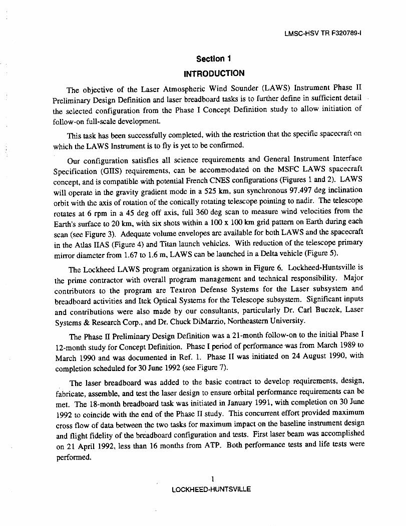
The objective of the Laser Atmospheric Wind Sounder (LAWS) Instrument Phase II
Preliminary Design Definition and laser breadboard tasks is to further define in sufficient detail
the selected configuration from the Phase I Concept Definition study to allow initiation of
follow-on full-scale development.
This task has been successfully completed, with the restriction that the specific spacecraft on
which the LAWS Instrument is to fly is yet to be confirmed.
Our configuration satisfies all science requirements and General Instrument Interface
Specification (GIIS) requirements, can be accommodated on the MSFC LAWS spacecraft
concept, and is compatible with potential French CNES configurations (Figures 1 and 2). LAWS
will operate in the gravity gradient mode in a 525 km, sun synchronous 97.497 deg inclination
orbit with the axis of rotation of the conically rotating telescope pointing to nadir. The telescope
rotates at 6 rpm in a 45 deg off axis, full 360 deg scan to measure wind velocities from the
Earth's surface to 20 km, with six shots within a 100 x 100 km grid pattern on Earth during each
scan (see Figure 3). Adequate volume envelopes are available for both LAWS and the spacecraft
in the Atlas HAS (Figure 4) and Titan launch vehicles. With reduction of the telescope primary
mirror diameter from 1.67 to 1.6 m, LAWS can be launched in a Delta vehicle (Figure 5).
The Lockheed LAWS program organization is shown in Figure 6. Lockheed-Huntsville is
the prime contractor with overall program management and technical responsibility. Major
contributors to the program are Textron Defense Systems for the Laser subsystem and
breadboard activities and Itek Optical Systems for the Telescope subsystem. Significant inputs
and contributions were also made by our consultants, particularly Dr. Carl Buczek, Laser
Systems & Research Corp., and Dr. Chuck DiMarzio, Northeastern University.
The Phase II Preliminary Design Definition was a 21-month follow-on to the initial Phase I
12-month study for Concept Definition. Phase I period of performance was from March 1989 to
March 1990 and was documented in Ref. 1. Phase II was initiated on 24 August 1990, with
completion scheduled for 30 June 1992 (see Figure 7).
The laser breadboard was added to the basic contract to develop requirements, design,
fabricate, assemble, and test the laser design to ensure orbital performance requirements can be
met. The 18-month breadboard task was initiated in January 1991, with completion on 30 June
1992 to coincide with the end of the Phase II study. This concurrent effort provided maximum
cross flow of data between the two tasks for maximum impact on the baseline instrument design
and flight fidelity of the breadboard configuration and tests. First laser beam was accomplished
on 21 April 1992, less than 16 months from ATP. Both performance tests and life tests were
performed.
1
LOCKHEED-HUNTSVILLE

LMSC-HSV TR F320789-1
$TM r_KIrR_ _/I_U
,COI.O X
S IVgLOCITT!
/
///
//
/
"_ 7
'NAOIRI
Figure 1. LAWS Baseline Design Flight Configuration
Figure 2. LAWS Package on Bus Assembly
2
LOCKHEED-HUNTSVILLE

LMSC-HSVTRF320789-1
Z
Z
), .....
12 o E 140 E !60 tZ 18
Figure 3. LAWS Shot Distribution
oE 2O
DIMENSIONS IN METERS
TAVAILABLE SPACEPLATFORM ENVELOPE
/i
T2 33 |
(9055) /
1 i(t36.22
ATLAS PAYLOAD _ -- -_ ......ADAPTER ENVELOPE [ I
Figure 4. LA WS/7;'OP in Atlas IIAS Large Fairing
Br312511-BE-06
o E 220
3
LOCKH EED-HUNTSVlLLI:

__j i 5 _T)
DELTA 6306 PAF / I
Figure 5.
1 7 METER(5 4 FT)
r!
LAWS in Delta Large Fairing
LMSC-HSV TR F320789-1
LAWS PROGRAM
W.F- Jones
Program Manager
D.I. Wilson
Deputy Program Manager &Chief Engineer
SECRETARY
P.G. Porter
SYSTEMSENGINEERING
T.K. Speer
Chief Systems Engineer
IPROGRAM OPERATIONS &
PLANNING
A.J. Condlno
I
I LASER SUBSYSTEM &
BREADBOARD
Dr. S.C. Kun.,ius
L Textron Defense Systems
S. Ghoshroy, PMDr. H.P. thou, Sys. Engr.
Br 320789-005
I OPTICAL SUBSYSTEMDr. W.W. Montgomery
SUBCONTRACTSADMINISTRATOR
J.T. Stelgerwald
IDESIGN
ENGINEERING
W,M. Harrison
L Itek Optical Systems
S.E. Kenddck, PM
C. Robbert, Sys. Engr.
Figure 6.
t UDAR I
LABORATORY
Dr. W.W. Montgomery
ISYSTEM PERFORMANCE
ANALYSES
Dr.W.R. Eberle
I
CONSULTANTS
_ Laser Systems & Res CorpNortheastern UnlversltySlmpsen Weather Assoc
UAH Center for Applied Optlcs
LAWS Program Organization
4
LOCKHEED-HUNTSVILLE

F320788-29
r-00
-1-mm
c"Z--4
r-"r-m
• Phase II ATP
• Project Reviews:
- Phase II Kickoff
- Quarterly Reviews- Phase II Final
• Phase Ih (21 months)
- Analysis/Trades; definition- Error budget
- Technology/Risk assess.
- Identify/Evaluate interfacerequirements
- Preliminary design
- Environmental analysis- Final report (Phase II)
• Laser Breadboard: (18 months)
- Development & test- Catalyst required for BB- Breadboard reqmts review- Initial BB design review
- Final BB design review- BB test readiness review
- Data reviews- Final data reviews
- Final report (Breadboard)
CY 1990
AIsIoINID•8-24
12-6V
i
12-6V
CY 1991 CY 1992
JIFIMIAIMIJIJIAIsI OI NID JIFIMIAIMIJIJ
Intedm GSFC DesignReview Review Review
3-5 5-5 6-27 7-31 12-12V V VV V
9-5
12-12
10-4
5-23
1-17
ATP
4-23
• 6-9 6-23
(MSFC)'(HQ)
u-30V
3-10
4-23• • 6-3o
• 6-;oi
•6.
r'-
o,"I"O_<
2O
Figure 7. LAWS Phase H Schedule
G3
0
o,

LMSC-HSV TR F320789-1
The results of the Phase II design and breadboard tests are that LAWS full-scale
development, verification, and successful mission operation are state-of-the-art technology. The
LAWS system engineering studies and breadboard demonstration show that our design is able to
accomplish the Science Team's requirements for global wind pattern measurements for theplanned 5-year mission.
6
.. LOCKHEED-HUNTSVILLE

LMSC-HSV TR F320789-1
Section 2
TRADE STUDIES AND BASEUNE DESIGN
Utilizing the selected LAWS configuration from the Phase I studies, system engineering
trades were performed to further develop and optimize our baseline configuration. The science
requirements, spacecraft resource budgets and interface requirements, launch vehicle loads and
volume envelopes, and the atmospheric phenomena and variables were all incorporated with the
subsystem's physical variables to ensure that the baseline design would meet all requirements
(see Figure 8). Sensitivity analyses were also performed to optimize the performance
requirements with respect to reliability and costs.
ScienceRequirements
• Troposphericwinds• _>6 pulses/horizontal
100 x 100 km• < 1 km vertical res.• System errorcontributionlimits_<1m/sline-of-sight
• Globalcoverage• Eye safe• 5 yr. life
10 g Laser pulses
Constraints _.
|
II
I
Atmosphere I I
• Aerosol seeding (10"llm'lsr "1)• Attenuation• Turbulence effects
- Coherence decorrelationtime (1,2, - - 5 i_s)
- Velocity variability
over _dd
Platform
• Power ResourcesAveragePeak
• Thermal Resources- Cooling&
Exposure• InstrumentResources
attitude & position• Orbit Parameters
Altitude & inclination• Structure
- Envelope&Mass- VibrationSpectra- Deformation
Design Variables
• Laser Parameters
- Pulse length- Pulse energy- Pulsechirp- Pulse spacing- Pulse spetial- Wavelength
• Optics Parameters- Aperture- Scan rate- Scan angle
• Receiver Parameters- Data rate
•Contamination -Dynamic range
• InterfaceL Cooling & Power ReqMass & Volume
InstrumentPerformance • AttitudeMonitor I
_.[ SNR & Pointing.... _ .... F320789-007
I DataUtility I
Error o r Coverage I,
Figure 8. System Level Trades
During Phase I, the requirements were developed for the LAWS system to enable it to
accurately measure the wind vectors on a global scale for five years. These requirements were
7
LOCKHEED-HUNTSVILLE

LMSC-HSV TR F320789-1
then allocated to either the entire LAWS system or to a specific element or subsystem (see Figure
9). These requirements include both "given" (from the SOW) and "derived" (lower level
requirements established to implement a higher level requirement, usually based on system trade
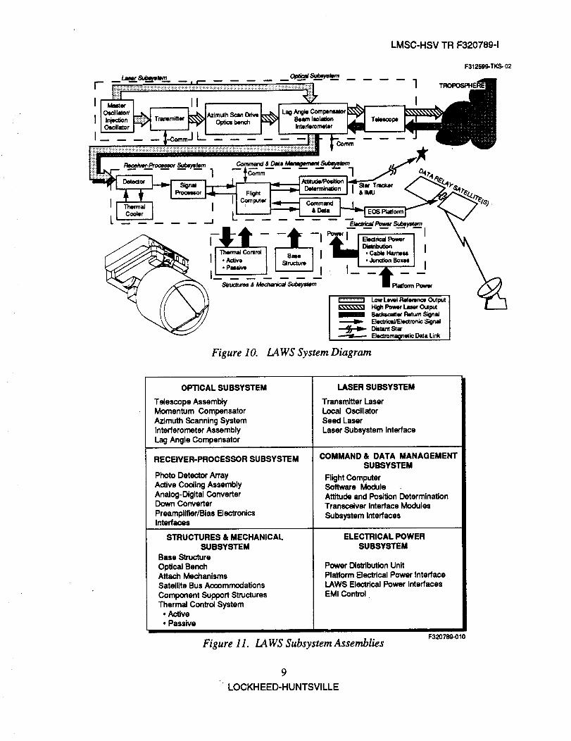
studies). They were integrated into a LAWS system diagram (Figure 10), which led to definition
of the six specific subsystems (Figure 11) needed to accomplish the mission objectives. (The
Thermal Control subsystem is part of the Structures and Mechanical subsystem but is discussed
separately in later sections of this document.)
Platform Atbtude/Position LEGEND
Transceiver Determination Allocation
Obtain OrbitalCommunicate Data
and Commands Parameters, Time,and Attitude
RightMemory Processor Instrurnentatlon
Store Process Data and Monitor Health, ISafety, and Status
Data Commands Data ITCS Laser
To AllScan Drive
Control Instrument Generate Laser Control Scan Position
Temperature Beam and Alignment
EPS Distribution Detector
Distribute I Detect and ProcessElectrical Power Return Signals
TDRSS L._ To All Payload |Satellite/Ground
Transceivers POCC DeveloperB
Transmit and H Decode and Monitor H Monitor
Receive Data _ data quality I_ 1 InstrumentPerformance
Te/escope
Expand, Direct, andReceive Beam
LaserOutput
BeamBeckscatter
Return
SconceDam
Evaluate Instrument IScience Data
F32OTSg-ooe
Figure 9. LAWS System Functional Flow Diagram
8
- LOCKHEED-HUNTSVILLE
LMSC-HSV TR F320789-1
F312569-TKS- 02
Figure 10. LAWS System Diagram
OPTICAL SUBSYSTEM
Telescope AssemblyMomentum CompensatorAzimuth ScanningSystemInterferometerAssemblyLag Angle Compensator
RECEIVER-PROCESSOR SUBSYSTEM
Photo Detector ArrayActive Cooling AssemblyAnalog-DigitalConverterDown ConverterPreamplifier/BiasElectronicsInterfaces
LASER SUBSYSTEM
TransmitterLaserLocal OscillatorSeed LaserLaser Subsystem Interface
COMMAND & DATA MANAGEMENTSUBSYSTEM
Flight ComputerSoftware Module -.Attitudeand PositionDeterminationTransceiver InterfaceModules
Subsystem Interfaces
STRUCTURES & MECHANICALSUBSYSTEM
Base StructureOptical BenchAttach MechanismsSatellite BusAccommodations
Component SupportStructuresThermaJControlSystem
• Active
• Passive
Figure 11. LAWS Subsystem Assemblies
ELECTRICAL POWERSUBSYSTEM
Power DistributionUnitPlatform ElectdcalPower InterfaceLAWS Electrical Power InterfacesEMI Control
F320789-010
9
LOCKHEED-HUNTSVILLE

LMSC-HSV TR F320789-1
The signal flow through the Laser, Optics, and Receiver subsystems, plus the volume
constraints of the candidate Arias IIAS and Delta launch vehicles, led to the baseline LAWS
flight configuration layout shown in Figure 12. The velocity vector is along the X-axis, with the
telescope bearing on the leading side of the Instrument platform, the laser on the trailing side,
and the telescope rotating about nadir. Dual Star Trackers are shown on the cold side of the
Instrument in close proximity to the inertial measurement unit (IMU). This configuration meets
all packaging requirements for the Atlas IIAS launch vehicle and can be accommodated by the
Titan vehicle and, with minor changes, the Delta vehicle. It is designed with clear access for
assembly, installation, checkout, and maintenance of all components before launch. Components
are located either around the perimeter of the Instrument base or on the optical platform. The
laser tank and telescope bearing are mounted to the Instrument base, with critical optical
components mounted to the optics bench, which is isolated from the base. The base is, in turn,
kinematicaUy mounted to the spacecraft. The optical bench provides a thermally and structurally
stable platform for mounting and alignment of critical optical elements. The telescope motor-
bearing assembly and laser pressure vessel are mounted directly to the base structure through cut-
outs in the optical bench. Baseline dimensions are shown in Figure 13 for the Arias HAS
configuration. Figure 14 shows the basic changes required for a Delta launch vehicle
accommodation. The LAWS Instrument with telescope can be fitted into a Delta (large) fairing
(Figure 5) by reducing the telescope aperture from 1.67 to 1.60 m diameter. This size reduction
results in a signal-to-noise loss of approximately 0.5 dB.LRSER PNR
TRRNSMIT LRSER _ !L"_: :.'_IF_..._--_ 7 RECEIVER "X2_"_ /_ [NTERFRCE !
THERNRL "-'1 _ / i C0HPUTER "'7
• . CORPUTER . -- ._.
: r-J-,,,,-..--.,ONE.II-,.7l-i ,, ,,,...,,
_b... CONTROLCRTOGEN ,C COOLER_ "_ _ _ 1 [_ l
HONENTUH CONPENSRTOR "-/
FOR CLRRI T¥
Figure 12. LAWS Baseline Configuration
10
LOCKH EED-HUNTSVILLE

LMSC-HSV TR F320789-1
TELESCOPE OMITTEDFOR CLRRITT 1
1,7M
OIMENS]ONS IN METERS(]NCHESI
3.65(1q3.70!
/
Figure 13. LAWS Baseline Dimensions
//i/'_.i.6METER
(5.3 F,,_
3.5 METER(I I .5 FT)
Figure 14. LAWS Configured for Delta Large Fairing
Due to the present uncertainty of the specific spacecraft and launch vehicle to be used for the
LAWS mission, Titan launch design load factors were used for all structural analyses for
11" LOCKHEED-HUNTSVILLE
LMSC-HSVTRF320789-1
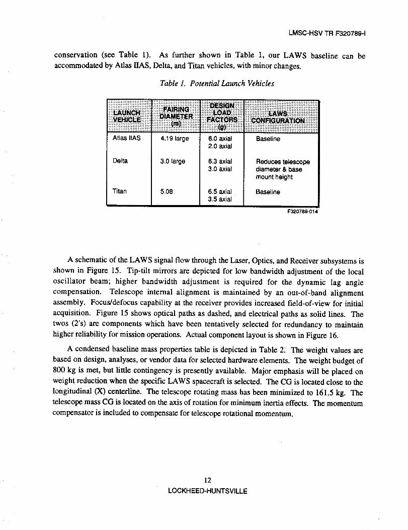
conservation (see Table 1). As further shown in Table 1, our LAWS
accommodated by Atlas HAS, Delta, and Titan vehicles, with minor changes.
Table 1. Potential Launch Vehicles
!iiiiiiiii!iii!i!i!i_i_i_i!iii_iii_iiiiiiiiiiiii_i_i_i_!i!_i_i_iiii:iiiiiiiiiiiiii!_!_iiii_iiiiiiiiiiiiiii!ii{i!!i!ii!_iii!iiiii!i!_!ii_!i!i!iiiiii!!!ili!:::::::i..........................._:::iiiiiiiiiiiiiiiiii!iiii!i_ii_iiiiiiiiiiiiiiiiiiiiiiiii_ii_!i!iiiiiiiiii!i!iiiiiiiiiiiiiii!iiii!!i!ii!!iiiiii!!i!!i_i!!_i_i!ii_
Atlas IIAS 4.19 large
3.0 largeDelta
Titan 5.08
6.0 axial2.0 axial
6.3 axial3.0 axial
6.5 axial3.5 axial
Baseline
Reduces telescopediameter & basemount height
Baseline
F320789-014
baseline can be
A schematic of the LAWS signal flow through the Laser, Optics, and Receiver subsystems is
shown in Figure 15. Tip-tilt mirrors are depicted for low bandwidth adjustment of the local
oscillator beam; higher bandwidth adjustment is required for the dynamic lag angle
compensation. Telescope internal alignment is maintained by an out-of-band alignment
assembly. Focus/defocus capability at the receiver provides increased field-of-view for initial
acquisition. Figure 15 shows optical paths as dashed, and electrical paths as solid lines. The
twos (2's) are components which have been tentatively selected for redundancy to maintain
higher reliability for mission operations. Actual component layout is shown in Figure 16.
A condensed baseline mass properties table is depicted in Table 2_ The weight values are
based on design, analyses, or vendor data for selected hardware elements. The weight budget of
800 kg is met, but little contingency is presently available. Major emphasis will be placed on
weight reduction when the specific LAWS spacecraft is selected. The CG is located close to the
longitudinal (X) centerline. The telescope rotating mass has been minimized to 161.5 kg. The
telescope mass CG is located on the axis of rotation for minimum inertia effects. The momentum
compensator is included to compensate for telescope rotational momentum.
12
LOCKH EED-HUNTSVILLE

"T
0v>,rr
>u_I
6u_
.2
mOld ItrUS#£ SAtVI "£I _.xnSi.d
ill_1_1
>cOI-Z
C_LUU.IIv00..J

o)o0f,.ooJ
OCh->oO"1"6
...i
(_0133130)S_37003 3IN300160_---
71_7d1711/dIl---_-
S_IOSS3_IclI_OD-jr
lno_arz_¢ouvalvoVaO g,i4l,_ "9I _ns,.e
£73-_ INnOW 3d0_37317
S_01¥7713S0 7 ¥3C. ,wll to,('G.Z---_c
%I
I/
l
/
L__
i7ddNS _3MOd q_3$¥7 IINSN¥_I
"IlllI
l-IJ
w.-I
>or)k-z
dww"1"v
0_1

Table 2. LAWS Baseline Mass Properties
t-OoXI"mm9CZ-t
r-r-m
System
Structure
Power
Thermal
Telescope
Laser
Data
Received
Detector
Momentum
Comp.
Pointing
Total
Contents
System
Weight(kg)
C.G. Location (m)
X Y Z
Base, Bench, Environmental Cover, Mounts 127.5
Distrubutor, Cable 13.6
Pump Package 15.5 * ,Heaters, Cable 92.95EOS Cold Plates 21 .**, Lines, Misc.
Mirrors, Reaction & Metering Structures, 204.6
TCS, Motor/Bearing, Misc.
Laser & Power Supp., Oscillators & Power 212.6Supp., Seed Lasers & Power Supp., Misc.
Computer, Cables 20.4
Electronics, Cryo Cooler, Controller 52.0
Compressors, Displacers, Bias, Preamp, Misc.
Momentum Compensator, Heat Exchanger 12.9
IMU, Star Trackers 41.0
-0.57 0.03 -0.34
-0.88 0.77 -0.32
-0.82 -0.02 -0.38
0.0 010 0.92
-1.20 -0.05 0.21
-0.79 0.29 -0.28
-0.26 0.62 -0.24
0.0 0./0 -0.62
-0.17 0.97 -0.50
777.5kg-0.55m O.08m 0.16m
* Could be replaced by platform pump if LAWS goes on dedicated platform.** Could be replaced with 5 kg heat exchanger if LAWS goes on dedicated platform.
Br 320789-017
I-
Go9IGo<
o-,4
LMSC-HSV TR F320789-1
Section 3
LAWS FULL SCALE DEVELOPMENT AND VERIFICATION
The guideline development schedule for the LAWS Phase C/D Full Scale Design,
Development, Test & Evaluation (DDT&E), was specified by MSFC for this Phase II study
contract. ATP was 1 January 1994, with launch scheduled for March 2001. The LAWS flight
unit was to be shipped for spacecraft integration on 1 January 1999, and the integral
LAWS/spacecraft configuration shipped for launch vehicle integration on 1 January 2001 (see
Figure 17).
The LAWS development process includes three units to minimize risk during the 5-year
DDT&E program. An engineering unit, a qualification unit, and a flight unit are used for a
success oriented, minimum risk approach. The engineering unit is maintained throughout the 5-
year orbital mission life for sustaining engineering and trend analysis activities. Initially the
engineering unit is constructed of non-flight components to allow an early start on system
integration, checkout, and performance testing (see Figure 18).
The qualification unit consists of flight configuration hardware to be tested to flight
centrification levels. Subsystem and components are required to pass acceptance level tests
before being subjected to full-up qualification level tests. Upon successful completion of
component and subsystem qualification testing as shown in Figure 19, the LAWS Instrument,
composed entirely of qualified units, will be subjected to vehicle qualification testing, as shown
in Figure 20.
Functional testing, as defined in MIL-STD-1540, will be performed immediately before and
after conducting all environmental testing. Functional testing is divided into two sections:
mechanical and electrical. Operation of the transmitter laser, elector-optical devices, software,
and data processing functions will apply to testing these sections. During mechanical testing, all
mechanical operational modes are fully operated and alignment tests are conducted. During
electrical tests, all primary and redundant circuits, commands, and operational modes will be
activated and sequenced as they will be performed in space.
Thermal vacuum tests will be conducted as a part of the vehicle qualification tests ( Figure
20) and flight unit acceptance tests (Figure 21) as required by MIL-STD-1540. During the first
and the last temperature cycles, a full functional test will be conducted at both the specified high
and low temperature extremes. Functional and operational parameters will be instrumented and
monitored during all test cycles.
16
LOCKH EED-HUNTSVILLE

I--0C)X"I-ram
9_-I- ..aCZ--4
r-T"m
MAJOR MILESTONES
Design and Development
Eng.Support
Software
SW Reqmt Specification
SW #zchitecture
sw DevelopmentSW Test & Implementation
SW Maintenance
Engineering Unit
Fab & Assembly
Sub Sys I & T
Sysl&T
oPs Support
Quantity Unit
lab & Assembly
SubSys I &T
Sysl&TQual Test
Right Unit
lab Assembly
Sub Sys I & T
Sys I&T
Bus Int
Bus/Veh Int
Sul)ort Launch/Orbit Fit
F-JeOperations
iiiiiiiiiiii_iii_i_/i_!iii_iiiii_iii_i!ii_iii/_!i!!i_ii!i_ii/!ii!iii_iliiliiiiiiii_ii/iiiiiiiiiiiiii!_.i!iii!ii:,ilii!iililiiiiliiliili_i iiiiiii!iiiiiiiii!!iiii!!iiiiiii!iii!iliiii_iiiiiiiiiii!iiiii_iiliiii!iiiiiii!iiiiiiii!!!_iii_iiil/iiiiiiiiii!!_ili!i!i!!:iliiiiii:i!ii.!i!_iiiiiil/!iiiiiiiLiiiiiiiiiiiiii_i;ii!iii_/.i:iiiiiiiiiiii:!_:_iiil/ii!iiiiii:iii:_ii_ii :/_ii_!ii_i!iiiiiiii_iii_!i_ii_il,x A z_ z_ ....'........................'FO,_ ,. LAw_.usZ__u__??PRR PDR CDR LAWS Ship FRR
I
7/94
oF==:_
r'--
i 72,_k
r'-"--'111 i6
r"
14/96
r'_7;g6
I'--
!ev97
"t7/I)7
g_7
_ ,.------...--.--I
II'm
I_t
-'-z
I_oT r---t
IM)7
F320789-018
Figure 17. LAWS Development Schedule
r
tl)
9I
<
",4

LMSC-HSV TR F320789-1
INTEGRATION
_ _ [ OPT_AL h
_ ] INJECT LASER _ [ CHECKOUT
__ INITIAL CHECKOUT J
EPS JLASER I
_NS. OPTICAL PATH I
TCS J
I _R II I_ER_REA_RO/BREADBOARD _]"_1 CHECKOUT !,
TE_E TELE_E1_ISTROC_RE_STRUCTURE .R,NG,STRUCTURE
MOCKUP _OCKUPFAa ENCODER;L_SYDESIGN .........
Figure 18. Development�Engineering Unit
_lDE_,OP.E.TII,M_IIT I
DEVELOPMENT IUNIT I
CH_KOUTj
SYSTEMS I
PERFORMANCE ITESTS J
BASE_ST,F_.Ess'LSTRUCTURE_ TEST_OPTICAL J BASE STRUCTURAL
BENCH _'--" I ASSY I]-IMECH/U_IC/U- F &C.G. V "I TESTSI -I TESTSI
KINEMATIC SPIN TEST • BASE FIXED
MOUNTS
I,,=1SIMULATORS
•F_TCOMPUTER• EPSJTELEscopEI_SHROUD' L._ ¢---..---Jn _TELESCOPEa I • INJECTION LASERS • POWERSUPPLY/L_ER• LOCAL OSCILLATORS ° TC,S
I _ J ASSY _ --= • RELAY MIRRORS • STAR TRACKERSBEARINGI-.Ji • MIRROR • LASER " ETC. ""ASSY|
BLANK• ENCOOER
SIMULATOR
ComponentLevelQualificationTests
BAKEOUTTHERMAL-VAC
SHOCK & VlBEMIPE RFORMANCE
Figure 19. Subsystem and Component Qualification Test
]8LOCKH EED-HUNTSVILLE

LMSC-HSV TR F320789-1
COMPONENT ILEVEL
QUAL TESTS J
l EMC
_wsASSEMBLY
FUNCTIONAL TEST
MECHANICAL
OPERATIONAL MODESALIGNMENT
ELECTRICALCIRCUITS
PRIMARY & REDUNDANTCOMMANDS ALLSEQUENCE THRU ALLOPERATIONAL
MODES
!
I
I ,.,°_,.H F°.O,,o_,.I---'"_" !-4o_o°.o _,_o_
-_lF°"°"°_LJFigure 20. Vehicle Qualification Tests
t
r
THERMAL IVACUUM
H STIFFNESS
TEST I J_
ISUBSYSTEM
BASEFAB / ASSY
I OPTICAl_FAB / ASSY
KINEMATIC }MO_TS
C&DH ]
All" _T }SYSTEM
RECEIVER / [DETECTOR
l SHROUD J LAWSSTRUCTURE + ASSY
ASSY I I FAB#m.SSYI t-- /i_,,1 + ,.Ml_O_ I - IsuesvSTEM/ C_-CKFAB / TEST
Figure 21. Flight Unit Asserr_ly and Test
FUNCTIONAL
F32078_021
TESTS I "
I_=,ic I
VACUUM
WEIGHT & IC,G.
19
LOCKHEED-HUNTSVILLE
LMSC-HSV TR F320789-1
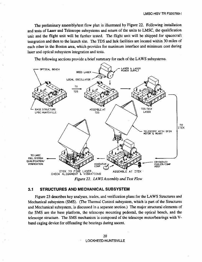
The preliminary assembly/test flow plan is illustrated by Figure 22. Following installation
and tests of Laser and Telescope subsystems and return of the units to LMSC, the qualification
unit and the flight unit will be further tested. The flight unit will be shipped for spacecraft
integration and then to the launch site. The TDS and Itek facilities are located within 30 miles of
each other in the Boston area, which provides for maximum interface and minimum cost during
laser and optical subsystem integration and tests.
The following sections provide a brief summary for each of the LAWS subsystems.
aTICAL BENCH _ f LASER & LASER
SEEO,,SE --- LOOWER
_-- BASE STRUCTURE ASSEMBLE AT TDS TEST
LMSC HUNTSVILLE TDS LASER
TO LMSC
FULL SYSTEM
QUALIFICATION/VERIFICATION MOHENTUH
COHP
ITEK TO FIRE LASER,CHECK ALIGNMENT & VIBRATIONS
Figure 22.
ASSEMBLE AT ITEK-
LAWS Assembly and Test Flow
TELESCOPE WITH SPINMOTOR & MOUNT
CRYOGENICCOOLER/COMPASSY
TO
ITEK
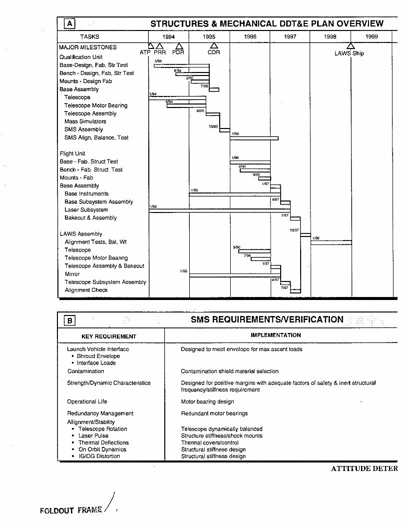
3.1 STRUCTURES AND MECHANICAL SUBSYSTEM
Figure 23 describes key analyses, trades, and verification plans for the LAWS Structures and
Mechanical subsystem (SMS). (The Thermal Control subsystem, which is part of the Structures
and Mechanical subsystem, is discussed in a separate section.) The major structural elements of
the SMS are the base platform, the telescope mounting pedestal, the optical bench, and the
telescope structure. The SMS mechanism is composed of the telescope motor/bearings with V-
band caging device for offloading the beatings during ascent.
20
LOCKH EED-HUNTSVILLE
_] STRUCTURES & MECHANICAL DDT&E PLAN OVERVIEW
TASKS 1996 1997
MAJOR MILESTONES
Qualification Unit
Base-Design, Fab, Str Test
Bench - Design, Fab, Str Test
Mounts - Design Fab
Base Assembly
Telescope
Telescope Motor Bearing
Telescope Assembly
Mass Simulators
SMS Assembly
SMS Align, Balance, Test
1994
',,/x /xATP PRR PDR
3/94
I8/94r----'
2/95
1/94
6294
I
1995
/,,CDR
7/95
"-'1
6/95
10/95
1/96
I
1/96Flight Unit
Base- Fab. Struct Test
Bench - Fab. Struct Test
Mounts- Fab
Base AssemblyBase Instruments
Base Subsystem Assembly
Laser Subsystem
Bakeout & Assembly
LAWS Assembly
Alignment Tests, Bal, Wt
Telescope
Telescope Motor Bearing
Telescope Assembly & Bakeout
Mirror
Telescope Subsystem Assembly
Alignment Check
ff94
1/95
1/95
4/96
I9/96
r-----1/97
3/96
[7/96
[--1/97
4F37
7/97
4/97
10/97
1998 Z_, 1999
LAWS Ship
-- 1/98
KEY REQUIREMENT
Launch Vehicle Interface
• Shroud Envelope• Interface Loads
Contamination
Strength/Dynamic Characteristics
Operational Life
Redundancy Management
Allignment/Stability• Telescope Rotation• Laser Pulse
• Thermal Deflections
• On Orbit Dynamics• IG/OG Distortion
SMS REQUIREMENTS/VERIFICATION :
IMPLEMENTATION
Designed to meet envelope for max ascent loads
Contamination shield material selection
Designed for positive margins with adequate factors of safety & inert structuralfrequency/stiffness requirement
Motor bearing design
Redundant motor bearings
Telescope dynamically balancedStructure stiffness/shock mounts
Thermal covers/control
Structural stiffness designStructural stiffness design
ATTITUDE DETER
./FOLDOUT FRAME

2000 / 2001
/_/_ LaunchLAWS Bus
VERIFICATION
Test & Analysis .
Test & Analysis
Test & Analysis
Test & Analysis
Test
Test
Test & AnalysisTest & Analysis
Test & AnalysisTest & Analysis
_ATION SUBSYSTEM
LMSC-HSV TR F320789-1
DESIGN ANALYSES & TRADE STUDIES
ITEM
Optical Bench*
Base Structure*
Telescope Pedestal
Laser Mounts*
SMS*
SMS
SMS
SMS
SMS
ANALYSES
To determine weight/stiffness/strength optimum for Honeycomb or
multiple truss core
To determine weight/stiffness/strength optimum for GE member
size and tayup
To determineweight/stiffness/strength optimum for material
trade ar,d design
To determine laser pulse effects on telescope pointing
To determine sensitivity of telescope imbalance on telescope
attitude & optics alignment
To dete_Tnine the effect of gravitational field alignment at on orbit
conditions
To determine changing structural design effects on dynamicmodes & natural frequencies (thereby, attitude control)
To determine space platform effects on attitude control
To determine thermal distortion effects on attitude control and
optics alignment
*Ongoing analyses begun in Phase B.
PLANNED TRADE STUDIES
TRADE ITEM BASELINE DESIGN
Telescope Support Pedestal
Optical Bench Core
Base Thickness
Titanium vs. Graphite Epoxy
Honeycomb vs. Multiple Truss
Thick, Thin, Medium (completed)
I-_ SMS VERIFICATION SUMMARY
SMA Qualification Structurew/Mechanism
SMS Flight Structure
in,4 O O.-- ¢1 _ ;g
O¢_ _ ;> 0 0
0 -- 0 E m u)0 _ "0 t-- _ 0 0e-
u. cn :E n- I- '< o.
X X Q Q Q Q Q
X X A A A A A
X = Same Levels Qual/Flight
Q = Qualification Test Levels*
A = Acceptance Test Levels*
* = Levels Per MiI-Std-1540B
Figure 23.
312594-MT-FO
Overview�Summary of the Structures
and Mechanical Subsystem (1 of 2)
_.... 21LOCKHEED-HUNTSVILLE

DYNAMIC TEST PLAN/FEATURES i
Free-Free Modal Test
Measure dynamic stiffness of spacecraft interface via impedance test
Combine results of these two tests to produce fixed base mode shapes and natural frequencies
- Test article suspended by air bearings
- All suspension system modes below 2 Hz
- Pure random excitation
- -50 + acceleration measurements
- Modal curve fitting techniques extract mode shapes, natural frequencies, and modal dam
RISK SUMMARY
RISK ITEM RISK LEVEL RISK REDUCTION APPROACH
Structural Assembly Failures Low
Motor/Bearing Failure
SMS Attitude Control Failure
Optics Alignment Failure
Low
Low/Med
Low/Med
- Large strength margins
- Early identification and control of fracture critical items
- Redundant motor wiring
- Similarity with other flight proven units
- Dynamic analyses with respect to space platform perturbanc
- High rev dynamic balance of telescope
- Deflection analyses supported by tests
- Thermal deflection analyses and testing
- Dynamic analyses with respect to space platform perturban(
REQUIRED SUBSYSTEM EQUIPMENT
COMPONENT SOURCE HERITAGE FLT QUAL MOCKL
Base LMSC New
Bench LMSC New
Telescope Mount Vendor New
Motor Bearing Vendor Modified Flight Proven
Telescope Vendor New
Mirror Vendor New
Test Hardware:
Mass Simulators LMSC New
Test Fixture LMSC New
1 1
1 1
1 1
1 1
1 1
1 0
1 ea
1
/

i!i: :if:i:
ENG
LMSC-HSV TR F320789-1
PLANNED SMS ANALYSES
ANALYSIS TYPE ALL SMS ALL SMS SMSEQUIPMENT STRUCTURES MECHANISMS
Strength
Dynamics
Thermal
Mass Properties
Producibility
Life Cycle Cost
FMEA
Reliability
Venting
Stress Controls
Performance
Math Model Verification
X
X
X
X
X
X
X
X
X
X
X
X
312594-MT-FO-2 of 2
PHASE B :_ _:;:_:_:_:: _: 1
MICsM_ __
Equipment packages are _/-----/_-_ "X_\_ j-_\
reproduced as point masses _,__%_ \_(not plotted). /////_ \_ --_ \ _
1454G/iedSents /J'//_ \,/_\_ \/_ ////
Figure 23. Overview�Summary of the Structuresand Mechanical Subsystem (2 of 2)
LOCKHEED-HUNTSVILLE

LMSC-HSV TR F320789-1
The base structure design is composed of structural edge beams with internal cross beams
covered by top and bottom face sheets. All components are constructed from graphic epoxy for
light weight, high strength, and low thermal coefficient of expansion. Three kinematic mounts
provide the structural interface between the LAWS Instrument and the spacecraft. All
components are sized for the launch loads with the prescribed safety factors.
The base structure is the mounting platform for the laser, telescope, and the majority of the
other subsystem components. The subsystem components are mounted around the perimeter on
the edge beams. The location is based on thermal requirements to take maximum advantage of
passive heating or cooling.
The optical bench is attached to the base structure by three kinematic mounts. The optical
bench is a honeycomb structure with face sheets, and is made of graphic epoxy material for
minimum distortions and light weight. The seed laser, local oscillator, detectors, and all relay
optical system elements are mounted on the bench.
3.2 COMMAND AND DATA MANAGEMENT SUBSYSTEM
The Command and Data Management (C&DM) subsystem is composed of a flight
computer, Star Trackers (2), inertial measurement unit (IMU), and command and data transceiver
interface modules. The flight computer, applying associated software, provides autonomous
direction to the LAWS Instrument, controlling when the laser is to be fired to achieve
measurements for selected wind components. The flight computer also receives and executes
commands from the spacecraft via the bus data unit (BDU) and exercises stored math models to
compute the time associated with the telescope pointing angles for the laser pulses. The Star
Trackers and IMU are located on the LAWS Instrument baseplate. Outputs from these sensors to
the LAWS Instrument are managed by the attitude and position determination elements of this
subsystem. The command and data transceiver assembles and transfers data from the LAWS
Instrument to the spacecraft for transmission via data relay satellites.
All communications with the LAWS Instrument, to and from the spacecraft, and with the
NASA control centers are directed through the LAWS C&DM subsystem via the BDU. The few
interfaces not controlled by this subsystem are related to the LAWS spacecraft electrical,
thermal, and mechanical interfaces. These interfaces, however, are monitored and reported by
the health and status instrumentation sensors.
The flight computer controls laser shot management firing commands, computes orbital
platform position location, collects telescope line-of-sight azimuth angle values for each laser
shot, provides short time storage of wind data for transmission to the spacecraft data management
system and formatting of data into Consultative Committee for Space Data Systems (CCSDS)
format, and performs other command and data management functions.
23
LOCKH EED-HUNTSVILLE

LMSC-HSVTRF320789-1
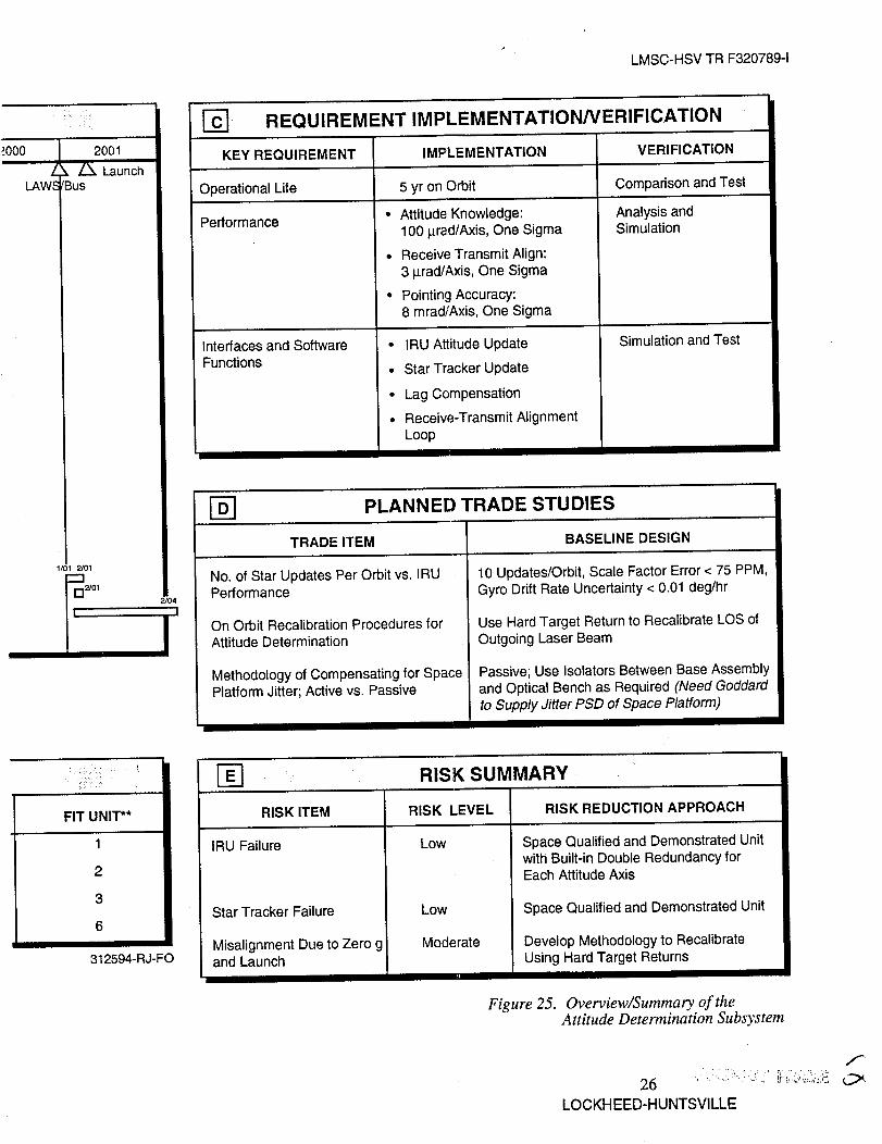
Figures 24 and 25 describe the key analyses, trades, and verification plans for the LAWS
Command and Data Management subsystem and the Attitude Determination subsystem,
respectively.
3.3 ELECTRICAL POWER SUBSYSTEM
The block diagram of the LAWS power Electrical Power Subsystem is shown in Figure 26.
The spacecraft's two 120 Vdc (GIIS-specified) power buses are labeled Platform +120 Vdc bus 1
and Platform +120 Vdc bus 2. The PDS will derive two redundant 28 Vdc power buses from the
spacecraft's two 120 Vdc power buses. Each of the two buses will be capable of supplying all
power required by the LAWS Instrument. Since both buses will be active simultaneously, each
bus will supply half of the LAWS power load. For clarity, the redundancy of individual
components in the PDS is not shown. The PDS will supply 120 Vdc to the transmit laser and 28
Vdc to the other LAWS subsystems. Only power distribution to the transmit laser, computer,
and receiver is shown in Figure 26. Power distribution to other LAWS subsystems is similar.
As shown in Figure 26, circuit breaker 1 and circuit breaker 2 will protect the spacecraft 120
Vdc power bus from faults in the LAWS system. Circuit breakers 3 and 4 will protect the PDS
dc/dc converters from faults occurring in the individual LAWS subsystems. These circuit
breakers will be remotely resettable. If a circuit breaker trips, it can be reclosed by commands
from the flight computer or spacecraft. The LAWS flight computer will monitor the health and
status of the PDS and issue commands to the PDS.
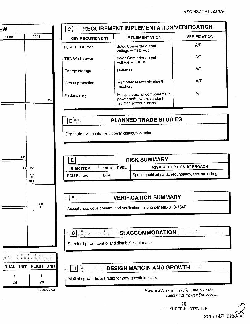
Figure 27 describes the phase C/D schedule, requirements, components, and verification
summary for the PDS.
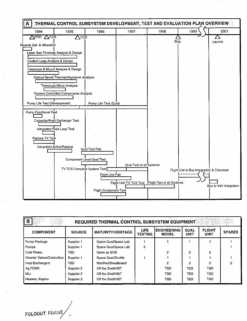
3.4 THERMAL CONTROL SUBSYSTEM
On-orbit thermal control for the LAWS Instrument is achieved by a hybrid form of thermal
control subsystem (TCS). An active fluid loop is used to transport the heat from high powered
components such as the main laser, oscillator, seed laser, and azimuth drive. The heat is
transferred through interfacing coldplates to be rejected to space via EOS central thermal bus
radiators. Heat is also rejected passively by radiation from external surfaces of all components
with an adequate field-of-view to space. Components are placed on the LAWS platform such
that, in combination with conventional passive thermal techniques, they are controlled effectively
within their allowable temperature limits by proper orientation during orbit (see Figure 28).
Passive thermal control is achieved by use of multilayer insulation (MLI), thermal coatings and
tapes, thermal covers, and thermal isolation materials. The passive TCS is based on HST TCS
design with a wide application of low t_/E atomic oxygen resistant Ag FOSR (a flexible optical
solar reflector composed of Teflon with vapor deposited silver) designed for a 15 year lifetime.
The TCS for the telescope and mirrors, although primarily passive, will need to be augmented
with heaters.
24
LOCKHEED-HUNTSVILLE

IEll •
TASKS
MAJOR MILESTONES
Design and Development
Eng. Support
Software
SW Reqmt Specification
SW Architecture
SW Development
SW Test & Implementation
SW Maintenance
1994
/xPRR PDR
C&DM REQUIREMENTS/VERIFICATIONi
1995 1996 1997 1998 /
ACDR LAWS Ship
7/94
11/94
i'--_--'-ls_ s
r------'_11 _I_
I
)S
1999
Engineering Unit
Fab & Assembly
Sub Sys I & T
Sys I & T
OPS Support
Quantity Unit
Fab & Assembly
Sub Sys 1 & T
Sys I & T
Qual Test
8/94
r----
1/95
14/96
r---17/96r
___._]6/97r'--1
9/97
17/97
[--------
11/99
L..._._ I
Flight Unit
Fab Assembly
Sub Sys I & T
Sys I & T
Bus Int
Bus/Veh Int
1/96
I6/97
I-----I 7r---
Suport Launch/Orbit Fit
Eng Operations
.... REQUIRED COMMAND AND DATA MANAGEMENT SYSTEM EQUIPMEN"
Bread- Development FliComponent Source Maturity/heritage boards* Units U
Flight processor NASA
Observatory bus interface unit
Oscillator Lockheed
So Atlantic anomaly detector
*Number of cards to be bread boarded
Modified NASNESs 2
0 2
Modified HSI 0 0
Modified/HEAO-2 0 1

2000 L
LAWS Bus
2001
Launch
I
Spares
. d
RI=OUIREMENTS
[_ IMPLEMENTATION/'"' -.... VERIFICATION _ •
Requirement Implementation Verification
Merge ENG and SCI data FP, BDU T, S
Selectable fixed and FP T
programmable telemeWformats
Command decoding FP Twith error detection
Digitalprocessingwith FP A, I100% margin
Timing accurate to 10"° FP, BDU A, Sin24 hr, time coding Oscillatorto within 100 izsecof UTC
High energy protect MCU, OBS T, ABDU, SAAD
*A = Analysis/simulation,I = inspection,S = Similarity, T = test
r_ PLANNED TRADE STUDIES
Structured vs. object oriented tech.ADA vs C language
RISK SUMMARY
RiskRisk Item Level Risk Reduction Approach
Commandprocessing
TLM formatand rates
Computerprocesses
Subsystemintegration
Safe modecontrol
Low Utilize existing designs asapplicable. EngineeringSpecialist (ES) to monitorprocess flow.
Low Utilize existing formats asavailable, provide hardwiredconflngenoy format. ES tomonitorprocess flow.
Medium New S/W design - ES toevaluate HW/SW design.
Low Identified hardware/softwaretest facility. Critical pathmonitored by ES. Assure QAsurveillance of parts used.
Medium Minor modification to existing
design. ES to monitorstandard process flow.
LMSC-HSV TR F320789-1
:t
r-_ vERIFICATION SUMMARY
Development testa
FP development test
Purpose: establish functional FP operation
Equip required: development unit,MCUdevelopment cards, test equipment
Integrated avionics test
Purpose: establish functional CDMSoperation of the MCU with BIUs via the serialbus
Equip required: tested MCU dev unit, atested OBS BIU development unit,a testedSt BIU development unit, a non-flight-itemoscillator,a vehicle systems simulator,andthe MCU test equipment
Environment: ambient
ShAD development test
Purpose: establish functional SAADoperation
Equip required: SAAD dev unit andstandarddigital test equipment
Environment: ambient
Qualification/acceptance testa
On units shown above
Purpose: individualequipment qualification
Equipment required: per unit as shownabove
Environment: ambient, thermal vacuum,thermal cycle, vibration, and EMI
SCIENCE INSTRUMENTACCOMMODATION PLAN
South Atlantic anomaly detectorprovideswarning toinstrumentsbased on software selectable thresholds.
Safe mode power control commands backup primaryscience instrument power switching system.
DESIGN MARGINS ". ._ AND GROWTH _ .
Processor sized to ensure 100% margininworstcase: average processor margin is 240%
Memory sized to ensure 100% margin in worst case;average margin provided is 260%
Serial bus provide 320% margin at I MHz
Bus design allows for additional BIUs
BlU design allows commandand telemetry to beadded in discrete increments by adding appropriatecards
Modular design allows the incorporation of newtechnologies
Figure 24. Overview�Summary of the Commandand Data Management Subsystem
25 /_
LOCKHEED-HUNTSVILLE

A'i-rlTUDE DETERMINATION PLAN OVERVIEWi
1996 1997 1998 1999/
TAS KS 1994 | 1995MAJOR MILESTONES_, Z_ _ A z_
A TP PRR PDR ST& CDRDesign & Devel. IRU
5/94
Inertial Reference Unit _ DeliveryStar Tracker
5/94 1/95
Interface Design I .=3_4Software Req'ts i:_57/94194 11951
Software DevelopmentFabrication !1_s 7195
Mech. I/F IElec. I/F I
Thermal Protection j
Alignment IF I
Integration lO_5 11/95
Eng. Unit ICE3._Qual. Unit 12/9 96
Flight Unit _98
Test support
Eng. UnitQual. Unit
Flight Unit
Engr. SupportBus. Integration
LV IntegrationLaunch SupportOrb. Verification
12/94
Att. Deter. Simulation r
7/96
r--m
1/97 6/97
m!
LAWS Ship
6/98 12/98
1/99 2/99
12/98
REQUIRED SUBSYSTEM EQUIPMENT
COMPONENT* SOURCE QUANTITY/UNIT ENG. UNIT QUAL. UNIT
Inertial Reference Unit
Star Tracker
Mechanical Interface
Cables
* "S" Parts
AD1
AD2
LMSC
LMSC
1
2
3
6
1
2
3
6
**Engineering Unit Components Used for Spares
LMSC-HSVTRF320789-1
?.000Z
LAWS
2001
X /X. Launch/Bus
1/01 2/01
2/01
KEY REQUIREMENT
Operational Life
Performance
REQUIREMENT IMPLEMENTATION/VERIFICATION
IMPLEMENTATION VERIFICATION
5 yr on Orbit Comparison and Test
Analysis andSimulation
Interfaces and SoftwareFunctions
• Attitude Knowledge:
100 i_rad/Axis, One Sigma
• Receive Transmit Align:
3 _rad/Axis, One Sigma
• Pointing Accuracy:8 mrad/Axis, One Sigma
• IRU Attitude Update
• Star Tracker Update
• Lag Compensation
• Receive-Transmit Alignment
Loop
Simulation and Test
2/04
,1
PLANNED TRADE STUDIES
TRADE ITEM
No. of Star Updates Per Orbit vs. IRUPerformance
On Orbit Recalibration Procedures forAttitude Determination
Methodology of Compensating for SpacePlatform Jitter; Active vs. Passive
BASELINE DESIGN
10 Updates/Orbit, Scale Factor Error < 75 PPM,
Gyro Drift Rate Uncertainty < 0.01 deg/hr
Use Hard Target Return to Recalibrate LOS of
Outgoing Laser Beam
Passive; Use Isolators Between Base Assembly
and Optical Bench as Required (Need Goddard
to Supply Jitter PSD of Space Platform)
RISK ITEM
IRU Failure
Star Tracker Failure
Misalignment Due to Zero g312594-RJ-FO and Launch
RISK SUMMARY
RISK LEVEL RISK REDUCTION APPROACH
Low
Low
Moderate
Space Qualified and Demonstrated Unitwith Built-in Double Redundancy forEach Attitude Axis
Space Qualified and Demonstrated Unit
Develop Methodology to Recalibrate
Using Hard Target Returns
Figure 25. Overview�Summary of theAttitude Determination Subsystem
LOCKHEED-HUNTSVILLE
f

I-"OOX"I"mmE3
CZ--I
r--r-m
Platform
+120V
Bus 1
-¢
Platform
+120V
Bus2
LAWS
, +_2v1-711'!!'1[
IDC/DC
Converter
1
LAWS
+120V
Bus 2
LAWS
+28V •
H*H
Transmit
Laser + 28 V
Computer + 28 V
Receiver + 28 V
Transmit
v Laser + 28 V
Computer + 28 V
"_ Receiver + 28 V
F320789-27
r-
(/)
9I(n<
0
(D
Figure 26. LAWS PDS Block Diagram

E_] ELE(:TRICAL POWER DISTRIBUTION SUBSYSTEM OVER_
1995 1998 1999TASKS
MAJOR MILESTONES
Design PDU
PDU Procurement
Fabricate PDU
Engineering Unit
Initial PDU Test
Assemble LAWS
Engineering Unit
Test LAWS
Engineering Unit
LAWS Engineering Unit
Support Operations
Fabricate PDU
Qualification Unit
PDU Qualification Test
Fabricate PDU
Flight Unit
Assemble LAWS
Flight Unit
LAWS Flight Unit Tests
LAWS/Spacecraft
Integration and Tests
1,94
1994
1/95
5/94 1/95
r'-'-"-------
1195
1/95 5/95
"--'---1
7/95
I
7/95 1/96
1/96
1996 1997
_96
I
7/96 _97
I
]
5/96
[
1/96 _
5/96
L
1
7i97
I
6/97
J
6/97
L
10/97
I
1/99
1/99
LAWS/Spacecraft/Vehicle
Integration and Tests
Launch
Orbital Verification1/94
Design Software
Implement and TestSoftware
Maintain Software
Write PDU test plansand procedures
Design PDU Special
Test Equipment (STE)
Fabricate PDU STE
Initial STE Test
5/95
I
10/@5
: • :i:i:i:)i _:iii!i;_i_ii:ii:Jii!iii_i!_i:!:i_ii!_,REQUIRED SUBSYSTEM EQUIPMENT:Iii;;_;_i!_i_!_" i:::
COMPONENT SOURCE MATURITY/HERITAGE MOCKUPS ENGINEERING UNIT
Power Distribution Unit
Cables
LMSC Modified/HST
LMSC Modified/HST
1
28
1
28
FOLDOUT FRA_4_
/
LMSC-HSV TR F320789-1
_W ::
2000 2001
1/01
1/01 3/01
3101
O3/01
I
1/0_
_] REQUIREMENT IMPLEMENTATION/VERIFICATION
KEY REQUIREMENT IMPLEMENTATION VERIFICATION
28 V + TBD Vdc
TBD W of power
Energy storage
Circuit protection
Redundancy
dc/dc Converter outputvoltage = TBD Vdc
dc/dc Converter outputvoltage = TBD W
Batteries
Remotely resettable circuitbreakers
Multiple parallel components inpower path; two redundantisolated power busses
I
PLANNED TRADE STUDIES
NT
AfT
NT
NT
A/T
Distributed vs. centralized power distribution units
RISK ITEM
PDU Failure
RISK SUMMARY
RISK LEVEL RISK REDUCTION APPROACH
Low Space qualified parts, redundancy, system testing
r-_ VERIFICATION SUMMARY
Acceptance, development, and verification testing per MIL-STD-1540
I
I
::!:ii_::i::.: SI ACCOMMODATION::,Standard power control and distribution interfaceI
QUAL. UNIT
1
28 I FLIGHT UNIT
1
28
F320789-02
: DESIGN MARGIN AND GROWTH :
Multiple power buses rated for 20% growth in loads
Figure 27. Overview�Summary of theElectrical Power Subsystem
2, 3LOCKHEED-HUNTSVILLE
L,-_/LDOU'I F

/
/
LMSC-HSV TR F320789-1Y
/
/
Y / LAWS Base
_- / (Z axis towards nadir)
Telescope
Earth Shadow _
¢ f
/ _ Orbit Plane
Figure 28. LAWS Instrument in Earth Orbit
SUN
Figure 29 shows the passive thermal coatings for the telescope and LAWS base components.
Figure 30 presents the Phase C/D summary for the development of the thermal control system.
3.5 OPTICAL SUBSYSTEM
The LAWS Optical subsystem has two major functions. It first acts as a transmitter in the
role of a beam expander, taking the 4 cm output of the 9.11 _tm laser and forming a 1.67 m
diameter beam which is scanned via a bearing assembly across the Earth's atmosphere.
Secondly, it performs the function of a receiver, acquiring the Doppler shifted scattered energy
from the troposphere. The Optical subsystem interferes with the LAWS laser via the transmitter
relay optics and with the LAWS receiver at the tip/tilt mirror, which performs dynamic lag angle
compensation.
The Optical subsystem functional flow diagram is shown in Figure 31. The selected baseline
design for the telescope is a two-mirror afocal configuration operating with a split field. With a
F/1.5 primary mirror, the telescope fits within the current packaging envelope. The transmit
optic axis is oriented off-axis by 0.2 deg in objects space in order to remove the course lag angle
resulting from the telescope scanning in azimuth and the round trip time for each transmitted
laser pulse. Compensator optics are required in the transmit path to balance focus error from
telescope field curvature. The receive channel is oriented on-axis. Pupil relay optics are required
to limit the size of the radiation through the scan bearing over the entire :k-0.3 mrad object space
29LOCKHEED-HUNTSVILLE

LMSC-HSV TR F320789-1
field-of-view. The pupil relay also creates a real pupil at which a single tip/flit mirror can correct
for second order dynamic lag angle compensation.
SHOWING PASSIVE TCS FOR TELESCOPE
NADIR
Z y (Se0_nd:prY0rMdlerrp00rsit)
/_"" Secondary Mirror Si
,,,,,,,, PrlmaryapM0rr°r p0slt)
Secondary Mirror Support Legs
Dtnmtlonof /Right X /
Note: • T4delcope not shownfor clarity
• FOSR - FlextbleOp(ICSISolarReflect¢_(Vapor delx_ltedAI ¢xrAg on back of TsiIon)
AI teflon tape outside)
NOTES:
• Average total absorbed orbitalheat fluxes used as the teta-scope revolves.
• Temperaturesshown .reminimum randrnaxlmumconsidering orbitbeta angle
Structure rsnge of sr to 9ooand 3 sigmaorbitalparameters
(AI teflon tape)
NADIR
(Ag FOSR) .
(_ FOSR)
(MU - TedIuo,u_r layer)
(White ZS3 Pmt- outskkAI Kapton - mkle)
Envlronmeltll/Tlltrnlll
Cover lot OpUc=(*J FOSa)
honeycomb) MM
Figure 29.
(B_)
FlightComputer(Black)
//
Cryo-cookprController
Thermal Radiation Model Plot of LAWS Instrument Showing Passive TCSSurface Coatings
3OLOCKH EED-HUNTSVILLE
_1 THERMAL CONTROL SUBSYSTEM DEVELOPMENT, TEST AND EVALUATION PLAN OVERVIEW
1994 1995
Z PRR/XPDR /kcDRI
leqmts Def. & Allocation
Laser Gas Flowlo Analysis & DesignI I
J
Coolant Loop Analysis & DesignI I
Telescope & Moun! Ana ysis & DesignI I
!
Optical Bench Thermal/Alignment AnalysisI I
!
Telescope Mirror AnalysisI I
Passive Contro ed Components AnalysisI I
IPump Life Test (Development)
1996
I
Pump Functional Test
ICaracitor/Heat Exchanger Test, I
Inte_luid Log Test
Passive "IV Test
i IIntegrated Active/Passive
[ I
1
1997
Pump Life Test (Qual)I
Qu al Test Fab
I II
Component Level Qual TestI I
I"IV TCS Comple :e System Test I
Flight Unit FabI I
I
Flight Unit TV TCS Test
Flight Compone!t Tes[ ]
I 1 I
1998
Qual Test of all Systems
I
Ship
2001
/xLaunch
Flight Unit to Bus Integration&Checkout
IFlight Test of all Systems
] I gis to Veh Integration
COMPONENT
Pump Package
Pumps
Cold Plates
Diverter Valves/Controllers
Heat Exchangers
Ag FOSR
MLI
Heaters, Kapton
LIFE ENGINEERINGSOURCE MATURITY/HERITAGE TESTING MODEL
1Supplier 1
Supplier 1
TBD
Supplier 1
TBD
Supplier 2
Supplier 2
Supplier 3
Space Qual/Space Lab
Space Qual/Space Lab
Same as EOS
Space Qual/Shuttle
Modified/Breadboard
Off the Shelf/HST
Off the Shelf/HST
Off the Shelf/HST
2
1
2
TBD
TBD
TBD
QUALUNIT
2
1
2
TBD
TBD
TBD
FLIGHT SPARESUNIT
1 1
1
2
1 1
2 2
TBD
TBD
TBD
FOLOOUT

-'] TCS REQUIREMENT IMPLEMENTATION/VERIFICATION
KEY IMPLEMENTATION VERIFICATIONREQUIREMENTS
1. Maintain laser gas tempat all PRF
2. Five year life on activecooling system
3. Maintain temp limits ofcomponents for allmission phases
4. Control of thermallysensitive optical bench,telescope & mirror/supports
5. Minimize contaminationof optics
6. Design for 5 year atomicoxygen environment
7. Decouple optics fromorbit environment
Convective heat exchangerwithin active cooling loop
Redundant pumps
_).Maintain struct tempgradients and changes tomeet pointing requirem"ts
Active cooling and passiveAg FOSR outer surfaces,MLI
Controlled by FOSR, heaters,ULE optics, gold coatings
Optical bench thermal cover ascontamination collector andspatial separation of fluid linesfrom optics
Teflon Ag FOSR, Aa = 0.012per year based on flight data
Thermal covers, Ag FOSR outer
surfaces, low mE external,thermal isolators
Analysis, test
Life test
Analysis, TVT
Analysis, TVT
Analysis, Tv'r
Analysis,LDEF data
Analysis, TVT
8. No single point failure Redundant pumps, valves Analysisheater systems
9. Maintain hardware and Safe mode developed with Analysiscomponents above heaters/thermostats to maintainsurvival temperatures component above lower survival
limits
Thermal cover, Ag FOSR andheater system
Analysis, TVT
D_ ::TCS TRADE STUDIES AND ANALYSIS
1. Position of passively controlled avionics components on the base.2. Compact convective heat exchanger versus back-to-back cold plates for
EOS/LAWS active thermal control interface.3. Pumped loop versus heat pipe active TCS.4. Redundant loops versus single loop with redundant pumps for active TCS.5. Existing space qualified pump packages versus new development
long life pumps.6. Passive versus active cooling of main laser power supply.
J •
E-_ :_:_il;i:_::iiiZii::!:ii:ii:iiii:_ii,::::,_::i::ilTcs,:_:RISK RE DUCTION SuM MARYii::iiii_illii::::iiiiiiiiiii::iii:_iiiiiii_iii_ii.:.:_.:_:<_:_:_:_:_::..:_:
RISK LEVEL RISK REDUCTION APPROACH
Five year pump life
Five year valve life
Five year life of other TCS compon.
Contamination due to outgassing
Contamination due to coolant leaks
Contamination due tobiological growth in coolant
High Life testing & redundant pumps
Med Cyclic testing
Low Stable materials
Low Material selection, bakeout & design
Low Use of brazed joints and leakcontainment devices
Low Sterilization system
LMSC-HSV TR F320789-1
VERIFICATION SUMMARY I
I L°ad ___ II Su_ey/Design Mode J
I
LaserBreadboard
Test
TCSComponent
TestsMath
Model
TCS
Design
IntegratedTests
Test VerifiedTCS
I _::_i:_iiiiiii; MARGINS AND GROWTH_i!ili_i;iii:
1. Using hot and cold design cases with 3_ fluxes
2. Range of equipment duty cycles and MLI/thermal coating performance
3. Heaters sized 1.5X required at minimum bus voltage
4. Controlling to levels well within requirements
5.2.0 x pump life
6. Redundant pump controller and power circuits
7. Redundant heaters & heater thermostats 312594-11
Figure 30. Overview�Summary. of the LAWSThermal Control System
LOCKHEED-HUNTSVILLE

LMSC-HSV TR F320789-1
FROMTRANSMITTER
Tip/TiltLag Angle
Compensator
lRECEIVER
TransmitterCompensator Transmit/
Optics ReceiveTelescope
'H IPeriscope ReceiverFollower Pupil Relay
Optics AlignmentSensor
SecondaryMotionControl
312594-23
Figure 31. Optical Subsystem Functional Flow Diagram
The periscope follower is a two-mirror assembly which rotates synchronously with the
telescope to fold the receive radiation back on axis. Telescope alignment is monitored by
additional active sensors and maintained by actuators controlling the location and orientation of
the secondary mirror. Other design features include a lightweight system with a 90 percent
lightweight ULE primary mirror, silicon carbide fold optics, and graphite epoxy structures. The
low residual waveform error is due to a low sensitivity design, the alignment maintenance
system, and the use of ULE with its virtually zero CTE and variation of CTE.
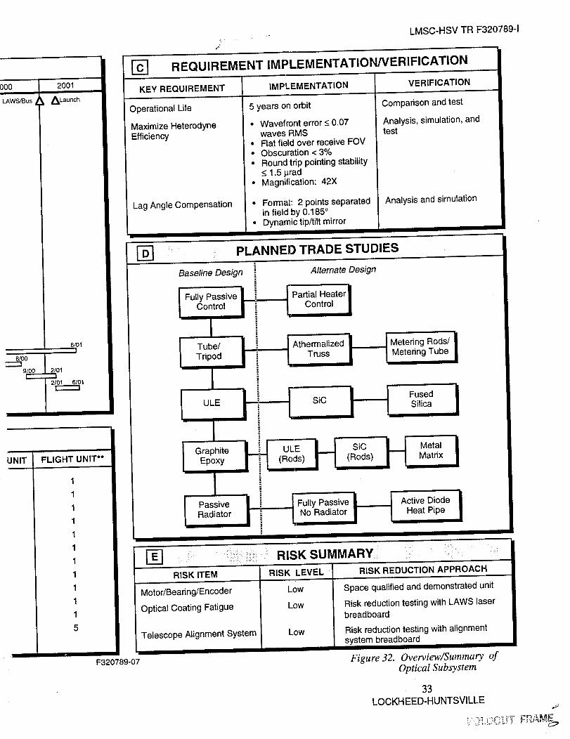
The Optical subsystem development schedule is shown in Figure 32 (block A). The major
long lead time items are the ULE blanks for the 1.67 m primary mirror. The first primary will
require approximately 9 months to fabricate.
Subassemblies for various units are listed in Figure 32 (block B). Key requirements,
implementations, and verification approaches are also shown in Figure 32 (block C).
3.6 RECEIVER/PROCESSOR SUBSYSTEM
The Receiver/Processor subsystem baseline is summarized as follows:
• Redundant HgCdTe photovoltaic detector arrays with 52 percent effective quantum
efficiency at 100 MHz and 43 percent at 1300 MHz (47.5 percent average)
• Mixing efficiency of 0.33 for uniformly illuminated annular aperture with ratio of
inner to outer diameter of 0.44
32
LOCKH EED-HUNTSVILLE

_] /_:i:!¸
Design &
Development
Preliminary design
Final design
Fabrication
Engineering Unit
Qualification Unit
Flight Unit
Integration
Engineering Unit
Qualification Unit
Flight Unit
Test Support
Engineering Unit
Qualification Unit
Flight Unit
Engineering Support
Sustaining Engineerin!
Bus Integr. Support
Launch Support
On-Orbit Calibration
& Align Support
5/94
|6/94I
OPTICAL SUBSYSTEM OVERVIEW
1996 1997 1998 [
LAWS
Ship
6/96
7/96I
2/97
3/97I
2/97I
1999
11/97i
8/97I
12/97
9/97I
7/97I
12/98I
10/98I
6/98 12/98I
1/99 I
REQUIRED SUBSYSTEM E( !UIPMENT
COMPONENT* SOURCE QUANTITY/UNIT ENGINEERING.UNIT QUA!
Primary Mirror Assembly
Secondary Mirror Assembly
Metering Structure
Reaction Structure
Transmit Relay Optics Set
Receive Relay Optics Set
Fold Optics Set
Thermal Control System
Azimuth Scanning System
Tip/Tilt Mirror
Telescope Alignment System
Mechanical, Thermal, Electrical,
and Optical Interfaces
* "S" Parts
Litton-ltek Optical Systems
Itek
Itek
Itek
Itek
Itek
Itek
Itek
Itek
Itek
Itek
LMSC
**Engineering unit components used for spares
1
1
1
1
1
1
1
1
1
1
1
5
1
1
1
1
1
1
1
1
1
1
1
5
000 2001
LAWS/Bus _,Launch
6/01i
=500 I91_01 1
FLIGHT UNIT**
1
1
1
1
1
1
1
1
1
1
1
5
LMSC-HSV TR F320789-1
I
REQUIREMENT IMPLEMENTATION/VERIFICATION
KEY REQUIREMENT
Operational Life
Maximize HeterodyneEfficiency
Lag Angle Compensation
IMPLEMENTATION
5 years on orbit
• Wavefront error _<0.07waves RMS
• Flat field over receive FOV. Obscuration < 3%• Round trip pointing stability
_<1.5 prad• Magnification: 42X
. Format: 2 points separatedin field by 0.185 °
• Dynamic tip/tilt mirror
VERIFICATION
Comparison and test
Analysis, simulation, andtest
Analysis and simulation
PLANNED TRADE STUDIES
Baseline Design
Fully PassiveControl
Tube/
Tripod
ULE
Alternate Design
Partial HeaterControl
hermalized Metering Rods/Truss Metering Tube
GraphiteEpoxy
IPassiveRadiator
FusedSiC Silica
ULE SiC Metal
(Rods) (Rods) Matrix
I FuyPassiveI IAOveD° eIi I No Radiator Heat Pipe
RISK ITEM
Motor/Bearing/Encoder
Optical Coating Fatigue
Telescope Alignment System
F320789-07
••i•71_. i_ii; RISK SUMMARY
RISK LEVEL RISK REDUCTION APPROACH
Low Space qualified and demonstrated unit
Low Risk reduction testing with LAWS laserbreadboard
Low Risk reduction testing with alignmentsystem breadboard
Figure 32. Overview�Summary of
Optical Subsystem
33
LOCKHEED-HUNTSVILLE ,_
_ _,_ _ _T F_-_,ME_

LMSC-HSV TR F320789-1
• Signal aligned on central element of array with exterior elements for alignment
monitoring
• Local oscillator beam tailored for central (signal) element for shot noise limited
operation with phase front matched to signal beam; spill over to alignment elements
• Redundant Split Stirling Cycle cryogenic coolers to optimize detector operating
temperature
• Redundant Split Stirling cycle cryogenic coolers to optimize preamp operating
temperature
• Bias supply and preamplifiers space-qualified versions of standard units
• Automatic gain control for wide dynamic range between aerosol and ground returns
• 10 bit 75 million samples per s analog-to-digital (A/D) converter for adequate wind
signal frequency response and dynamic range.
The LAWS Receiver/Processor subsystem consists of a wide bandwidth photo detector
array, active cooling for the photo detector, bias circuitry, preamplifiers, and on-board signal
processing electronics. For each of these components, several options were considered before
the selection of the baseline Receiver/Processor subsystem components.
Figure 33 is the Receiver/Processor subsystem block diagram. The local oscillator optical
source (upper left hand comer of Figure 33) from the master oscillator is expanded to match the
4 cm diameter of the beam received from the telescope before being focused on the photo
detector. The Doppler signal is received from the telescope and optical train, superimposed on
the local oscillator, and directed toward and focused on the photo detector array. Cooling is
provided for the detectors. Outputs from the detectors are amplified and frequency shifted to the
frequency/amplitude range of the A/D converter. The "zero" Doppler (relative to the ground) is
set for the center of the 0 to 30 MHz baseband to minimize A/D frequency span requirements.
The levels of each channel from the detector array are measured to monitor the received optical
signal spot location upon the detector array for optimal alignment. The output of the A/D is
buffered and telemetered to the platform data interface. The Receiver/Processor development
schedule is shown in Figure 34.
3.7 LASER SUBSYSTEM
The CO2 Transmitter Laser subsystem is shown in the block diagram in Figure 35. The
following components make up the Laser subsystem:
• Optical resonator
• Electrical discharge
• Pulse power supply
• Pressure vessel structure
• Gas flow loop
34
LOCKHEED-HUNTSVILLE
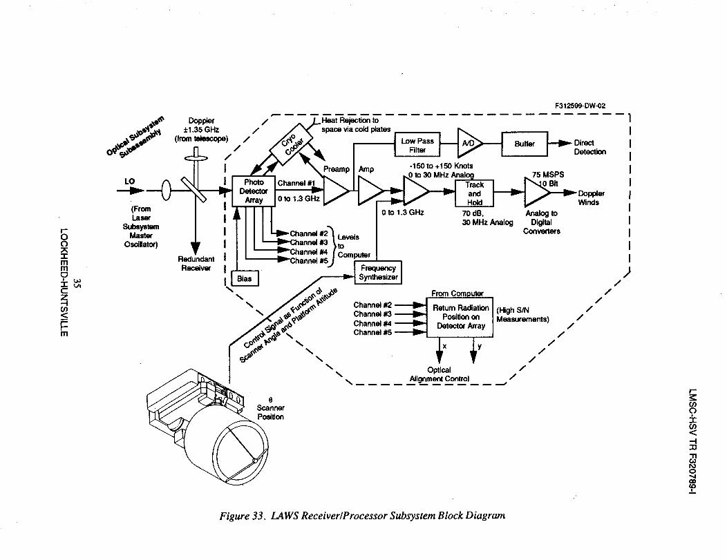
I-"OO
Imm0
CZ--t
<r-r-m
F312599-DW-02
Redundant
Receiver Frequency
Synthesizer
From Computer /
Channel #2 Return Radiation (High S/N /
Channel #3 Position on Measurements) /
Channel #4 DetectOr Array /
Channel #5 /
\ /\ /
Optical /\
Alignment Control _,. /
Scanner
Position
/
/
I'-z:O0
9I
<
:13
0",,4
Figure 33. LAWS Receiver�Processor Subsystem Block Diagram

TASKS
MAJOR MILESTONES
Design & Devel.Detector ArraysElectronics
Bias, Amps, SW
A/D, Controls
Optics
Cryo CoolersInterfaces
Software
Fabrication
ComponentsInterfaces
Integration
Eng. UnitQual. Unit
Flight Unit
Test Support
Eng. UnitQual. Unit
Flight Unit
Engr. Support
Bus. Integration
LV IntegrationLaunch SupportOrb. Verification
Att. Deter. Simulation
RECEIVER / PROCESSOR PLAN OVERVIEW
1994 1995
LA A AATP PRR PDR CDR
8_
1996 1997
1998 Z_ 1999
LAWS Ship
r------I
3/94 1195
' I! I
1/95 7/95
12194
I
I
9/95 11195
r--i
--11196
6/96
1/97 6/97
5/98 12/98
1/99 2/99
"-i
12/98
REQUIRED SUBSYSTEM EQUIPMENT
COMPONENT* SOURCE QUANTITY/UNIT ENG. UNIT QUAL. UNIT
Detector Array
Support Optics
Support Electronics
Bias ckt, Amps
A/D Conv., Controls
Cryo Cooler Assembly
Cables
RP 1
RP 2
RP3
RP4
LMSC
LMSC
2
1 set
1 set
2 sets
4
2 sets
2
1 set
1 set
2 sets
4
2
2
1 set
1 set
2 sets
4
2
* "S" parts** Engineering unit components used for spares
FOLDOUT FRAME

Z_ 2o01_. Launch
LAWS/Bus
1/01 2/01
%I
FLIGHT UNIT**
2
1 set
1 set
2 sets
4
2
F320789-01
LMSC-HSV TR F320789-1
REQUIREMENT IMPLEMENTATION/VERIFICATION
KEY REQUIREMENT IMPLEMENTATION VERIFICATION
Operational Life • 5 yr on orbit Comparison and test• No single point fail Analysis and test
Performance
Interfaces and SoftwareFunctions
• A/C quantum effect
• Closed loop tracking
• Acceptable aging
• Temperature control
• Data handling/control
• Ground retum alignment
• Automated gain control
• Data digitization & storage
• System performancemonitor
Measurement
Analysis, measurementand simulation
Measurement, analysis,
comparison
Measurement and analysis
Simulation
Simulation and test
I
r_ PLANNED TRADE STUDIESTRADE ITEM BASELINE DESIGN
Cooled vs. uncooled Amps
Number of pre-amps for signal detector
Redundant vs. nonredundant
Adjustable focus vs. fixed miniscus lens
Dual tip-tilt vs. single for L.O. adjustment
Number of array elements
Cooled where noise figure is improved
Baseline is four switched pre-amps
Redundant detectors and coolers
Adjustable focus
Dual
Four alignment plus central
RISK SUMMARY
RISK ITEM
Detector Failure
Loss of S/N from
misalignment
Cooler failure
RISK LEVEL
Moderate
Moderate/Low
Low
RISK REDUCTION APPROACH
1. Produce several batches of detectors and perform
accelerated aging tests.
2. Design with redundant detectors.
1. Design for graceful S/N loss from misalignment.
2. Design for low BW on orbit alignment correction.
1. Lockheed developing/qualifying under EOS-A
contracts.
I-_ PERFORMANCE ENHANCEMENT TOOLS
ITEM
Detector A/C
quantum efficiency
POTENTIAL ENHANCEMENT
Perform 18 to 30 month development/test effort; anticipate 30 to 60 %
performance improvement.
Figure 34. Overview�Summary of the
Receiver�Processor Subsystem
36LOCKHEED-HUNTSVILLE
FOLDOUT F=_.'_
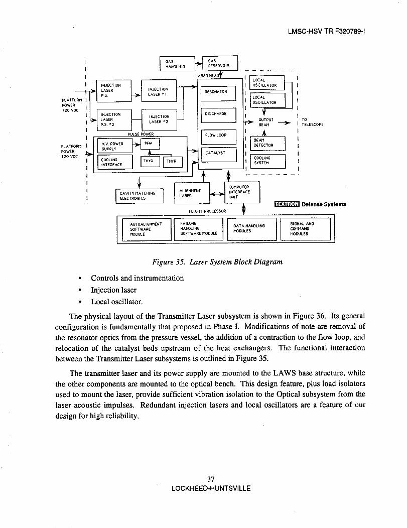
LMSC-HSV TR F320789-1
I
I
I
PLATFD_'_
POWERI
120 VDC _
POwERPLATFORtl._
120 VDC
LASER
PS.
INJECTION
LASERP.S. _2
I GAS _ GASHANOL ING RESERVOIR
LASER HE A0_I_
INJECTION ]_ RESONATOR
LASER • I I
IINJECTION DISCHARGE
LASER w2
I LOCAL
OSCILLATOR
I LOCALOSCILLATOR
.__ OUTPUTDEAN
PULSE POWER FLOW LOOP ,I,
TOTELESCOPE
H.V. POWER DETECTORSUPPLY
CATALYST
COOLING COOLING
INTERFACE SYSTEM
......
OHPUT I
CAVITY MATCHING ALIGNMENT
ELECTRONICS
Defense SystemsFLIGHT PROCESSOR ._
AUTOALIGNMENTSOFTWARE
MODULE FAILURE I DATA HANDLING IHANOL ING MODULESSOFTWARE MODULE MOOULESSIGNALCOII'IANOAND I
Figure 35. Laser System Block Diagram
• Controls and instrumentation
• Injection laser
• Local oscillator.
The physical layout of the Transmitter Laser subsystem is shown in Figure 36. Its general
configuration is fundamentally that proposed in Phase I. Modifications of note are removal of
the resonator optics from the pressure vessel, the addition of a contraction to the flow loop, and
relocation of the catalyst beds upstream of the heat exchangers. The functional interaction
between the Transmitter Laser subsystems is outlined in Figure 35.
The transmitter laser and its power supply are mounted to the LAWS base structure, while
the other components are mounted to the optical bench. This design feature, plus load isolators
used to mount the laser, provide sufficient vibration isolation to the Optical subsystem from the
laser acoustic impulses. Redundant injection lasers and local oscillators are a feature of our
design for high reliability.
37
LOCKH EED-HUNTSVILLE
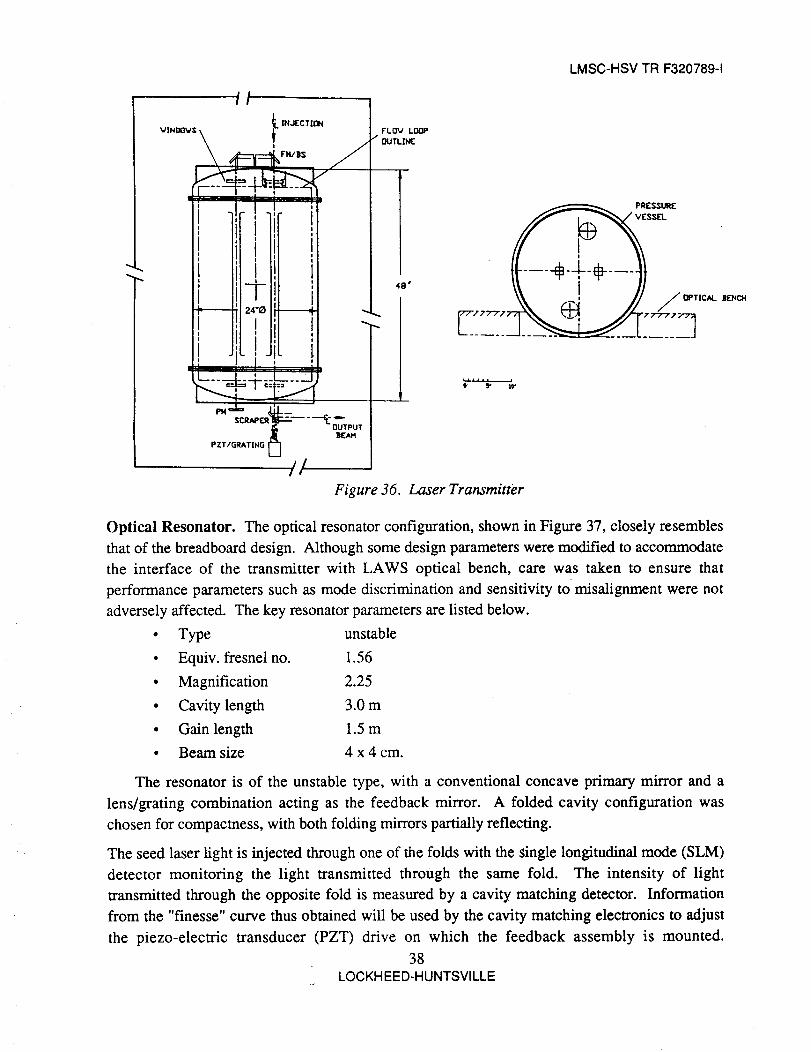
LMSC-HSV TR F320789-1
!1
f IN,JECTION
VIN_WS
FH/i$ //
i i
i .I., iI, !I It
f-P------- 24"0
I iii
I . i .
1: I _"LL.... ..L__..L__J
¢_¢_ / __._¢C nUTPUTSCRAP(
_, )[AM
PZT/GRATING [_]
//
F'LI3V LOOP
/ DtJTLINE
48"
Figure 36. Laser Transmitter
Optical Resonator. The optical resonator configuration, shown in Figure 37, closely resembles
that of the breadboard design. Although some design parameters were modified to accommodate
the interface of the transmitter with LAWS optical bench, care was taken to ensure that
performance parameters such as mode discrimination and sensitivity to misalignment were not
adversely affected. The key resonator parameters are listed below.
• Type unstable
• Equiv. fresnel no. 1.56
• Magnification 2.25
• Cavity length 3.0 m
• Gain length 1.5 m
• Beam size 4x4 cm.
The resonator is of the unstable type, with a conventional concave primary mirror and a
lens/grating combination acting as the feedback mirror. A folded cavity configuration was
chosen for compactness, with both folding mirrors partially reflecting.
The seed laser fight is injected through one of the folds with the single longitudinal mode (SLM)
detector monitoring the light transmitted through the same fold. The intensity of light
transmitted through the opposite fold is measured by a cavity matching detector. Information
from the "finesse" curve thus obtained will be used by the cavity matching electronics to adjust
the piezo-electric transducer (PZT) drive on which the feedback assembly is mounted.
38
LOCKHEED-HUNTSVILLE

LMSC-HSV TR F320789-1
_. ....... -f,
III
It
I
TRANSMIT LASERPOWER SUPPLT
TRANSH|T LRSER
J
/"
, fI!
I
Defense Systems
Figure 37. Resonator Optics Layout
Laser output energy is extracted by a scraper mirror located near the feedback assembly and
measured by the pyrodetector located between the scraper and the telescope. The primary and
scraper mirrors will either be made of copper or dielectrically coated silicon substrates, while the
folding mirrors and pressure vessel windows will be made of ZnSe to allow alignment in the
visible regime.
Flow/Discharge Subsystem. These assemblies have been defined as one subsystem because of
their high level of mechanical integration and functional interdependencY. As Figures 38 and 39
indicate, the layout closely matches that of the breadboard. Differences arise primarily in the
choice of materials and addition of redundant components wherever failure mode analysis and
breadboard lifetime tests indicate a need.
39
LOCKHEED-HUNTSVILLE

LMSC-HSV TR F320789-1
FLOW
TUBE/FIN HEATEXCHANGER
INLINE CATALYTIC MONOLITH
WINDOW
LOOP SUPPORTS
CONNECTOR
IMPELLER OUTER SHROUD
CROSS FLOW BLOWER
CONTRACTION (PERFORATED)
MUFFLER
CATHODE
HI VOLTAGE FEEDTHRU
CATHODE HOUSING
PREIONIZER
FLOW CONDITIONING
PRESSURE VESSEL
24 IN. OUTSIDE DIA
Defense Systems
Figure 38. LAWS Discharge�Flow Loop, End View
IPPORT CENTER COUPUNG & FAN SUPPORT
IMPELLER OUTER SHROUD
:ROSS FLOW BLOWER
PREIONIZER
WINDOW MOTOR&
MAGNETICCOUPLING
CATHODE
H.V. FEEDTHROUGH
FLOW LOOPSUPPORTS
PERFORATED PLATE
TUBE/FIN HEAT EXCHANGER
_) Side View PRESSURE VESSEL24.12 OUTSIDE DIA
VACUUM CONNEC_ON
Figure 39. Two-Electrode Configuration, Side View
40LOCKHEED-HUNTSVILLE

LMSC-HSV TR F320789-1
A UV preionized self-sustained discharge scheme was chosen with four electrode pair
modules (two per side) providing redundancy and eliminating alignment and current distribution
problems associated with long electrodes. A modified Ernst profile was selected for the cathode
based on extensive electrostatics code calculations substantiated by the DVT results. A flat
anode profile was chosen for flow compatibility and compactness. Preionization is achieved
through holes in the anode utilizing a dielectric/corona bar assembly. The preionizer housing
dielectric material can be machined and is impermeable. The relevant operating parameters of
the discharge are listed below.
• Gas mixture
• Gas pressure
• Discharge dimensions
• Pulse length
• Specific energy loading
• Discharge voltage
3:1:1 He:CO2:N2
0.625 atm
4.2 x 4 x 150 cm
3.2 - 4.0 l_S
86 J/L
21-23 kV
Flow Loop. The flow loop is designed to accommodate the discharge assembly described in the
previous section. It provides fresh gas to the discharge and moves the used hot gas at the
appropriate speed to prevent arcing. This gas is subsequently reconditioned by the catalyst bed,
where recombination of CO and O into CO2 dissociated during the discharge occurs.
Subsequently, the thermal energy resulting from the inefficiencies inherent in the laser kinetics
processes is removed by a fan and tube heat exchanger. The sidewall mufflers, located in both
sides of the cathode, attenuate the acoustic waves generated by the discharge in order to maintain
the homogeneity of the lasing medium in the cavity below the levels dictated by beam quality
and cavity matching requirements.
Key features of the flow loop design are the dual tangential fans chosen for both
compactness and modularity, the contractions upstream of each discharge which assist in
restoring flow uniformity, and the skewed positioning of the catalyst bed and heat exchanger
which provides compactness and causes a gradual equilibration and cooling of the hot gas. This
last feature minimizes density perturbations to the laser medium which could otherwise affect the
medium homogeneity in the cavity. The relevant flow parameters are listed below.
• Mass flow rate
• Flow velocity in cavity
• Fan speed
• Cavity flush factor
• Available catalyst volume
• Porosity of muffler wall
23 g/s
1.26 m/s
1700 rpm
3.0 at 10 Hz
12.6 L
3 percent - no packing resistance
Backup Design: 30 percent - 1 cgs rayls/cm
41
LOCKH EIED-HUNTSVlLLI=

LMSC-HSV TR F320789-1
Pulse Power. The pulse power system in a discharge pumped CO2 laser is formed by three
primary components: a high voltage dc-dc converter, a pulse forming network (PFN), and a
thyratron. The function of the high voltage power supply is to step up the 120 Vdc prime power
input to the 40 kV charge voltage required by the PFN. The PFN in turn is charged by this power
supply and, upon switching by the thyratron, generates a pulse with the desired length as well as
voltage and current characteristics. The pulse energy is subsequently discharged into the gas by
the discharge assembly described in the previous section. A functional diagram of these
processes is shown in Figure 40.
01$¢,OI_ECT6_aTC,H
120Vdc+1-10%_
Pt_ITORM
MONITORSlGNN.S
&FAULTgGNN.S
I_IERFACE
me,-V"
40KvOUTPUT
(
A3Vdc
MOOULE$
TOO_Wt_
V,OOUES
I
IJ 1
I-I
120Vde
PLA_OflM
Figure 40. Energy Discharge Processes
The configuration of the PFN, shown in Figure 41, will be an E-type, thyratron switched
scheme similar to that utilized in the breadboard. Primary differences will arise in the choice of
lighter weight, space qualified components, particularly capacitors, and the use of redundant
critical components such as the thyratron, capacitors, and diodes. Also, because operating the
PFN in a pressurized environment would result in a considerable weight penalty, vacuum
operation is anticipated. This will require mounting components on a coldplate and active
cooling of the thyratron. The operating parameters of the pulse power subsystem are listed
below.
• Total energy stored in PFN 264 J
• PFN charge voltage 40 kV max
• PFN current <2.5 kA
• Total capacitance 400 nF
• Pulse length 4.5 ps max
• PRF 10-15Hz
The development schedule for the Laser subsystem is shown in Figure 42.
42LOCKHEED-HUNTSVILLE

LMSC-HSV TR F320789-1
L
P2518
t6
I_t__
1
2_++ ,
f6
I
SCREWS
28 MIN.
I" t_°°__°+c38kV DC
I . . ,
,,RES._ / i
PLAN VIEW
i J
----f--6
L
I
GRID PULSER
AND 120V - lkVCONVERTER
I
ELEVATION VIEW DIM. IN tNCHES
Figure 41. Preliminary Layout of Pulsed Power Section
43LOCKHEED-HUNTSVILLE

LASER TRANSMITTER PLAN OVERVIEW
TASKS
MAJOR MILESTONES
Engineering Unit
Design & Spec. Prep.Procurement:
Long Lead Times I"Assembly/Construction &
Check Out of Components
Functional Tests of Sub- IAssembly Comp. Chk. Out
Shock/Vibration Tests
Subsystem integrationLaser Tests @ TDS
Eng. Unit Laser Tests@ LMSC
Qualification unit
Design & Spec. Prep.ProcurementConstruction
Functional Testing ofLaser subassemblies
Subsystem integrationLaser Qualification Tests
@ TDSQual. Unit Laser Tests
@ LMSC
Flight UnitProcurement: Long Lead
Items
Fabricate, Assemble, WireFunct. Testing
Subassemblies
Subsystem Integration &Laser Testing @ LMSC
1994
' ZX ZXATP PRR PDR
6/94
10/94 I
I
I1/95
7/94
r_
1995
/kCDR
1996
SHIP ENGUNIT TO
LMSC
6/96
r
1997
5/95
I
6/95 __
!
1/96
4/96
lO_6r-/
LASER
I&T
1/96
QUAL UNIT TESTS 9/97
1998 1 1999
LAWS Ship
I
SHIP FLIGHT10/96 ] UNIT TO
LMSC 6298
9/97
r-------
REQUIRED SUBSYSTEM EQUIPMENT
COMPONENT* SOURCE QUANTITY/UNIT ENG. UNIT QUAL. UNIT FLIGHT UNIT**
Pulsed Power Laser
Discharge Cavities
Flow Loop/Fans/Catalyst
Pressure Vessel
Pulse Forming Network
Thyratrons
Pulsed Power Supply
Optical Resonator/Bench
CW Injection Laser
Single Mode PZT Controller
CW Local Oscillator Laser
Controls and Instrumentation
Alignment Laser and Mechanism
Laser Thermal Control System
TDS
TDS
TDSNOP
TDS
TDS
TDS
ALE
TDS/LMSC
MPB
BURLEIGH
MPB
TDS
ITEK
TDS
1
2
1/2/2
1
1
2
1
1/1
2
1
2
1
1
1
* "S" parts** Engineering unit components used for spares
1
2
1/2/2
1
1
2
1
1/1
2
1
2
1
1
1
1
2
1/2/2
1
1
2
1
1/1
2
1
2
1
1
1
1
2
1/2/2
1
1
2
1
1/1
2
1
2
1
1
1
F320789-050
®
Fan Failur
Individual
Catalyst C
Thyratron
PFN Cap_
Feedback
Mirror Dar
FOLDOUT FR_:L_iiE/'
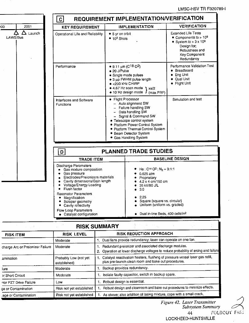
}00 _, 2001//_ Launch
LAWS/Bus
LMSC-HSV TR F320789-1
REQUIREMENT IMPLEMENTATION/VERIFICATION
KEY REQUIREMENT IMPLEMENTATION VERIFICATION
Operational Life and Reliability • 5 yr on orbit
• 109 Shots
Performance
Interfaces and Software
Functions
• 9.11 lain (C18 02)• 20 J/Pulse
• Single mode pulses
• 3 p.p FWHM pulse length• <200 kHz CHIRP
• 4.67 Hz scan mode "1.xrd2
• 10 Hz design mode ] (max PRF)
• Flight P,,ocessor
- Auto alignment SW- Failure handling SW- Data handling SW
- Signal & Command SW
• Telescope control system• Platform Power Control System• Platform Thermal Control System
• Beam Detector System• Gas Handling System
I-DI PLANNED TRADE STUDIES
TRADE ITEM BASELINE DESIGN
Extended Life Tests
• Components to > 109
• System to > 3 x 10⁸Design for;Robustness and
Key Component
Redundancy
Performance Validation Test
• Breadboard
• Eng Unit• Qual Unit
• Flight Unit
Simulation and test
Discharge Parameters• Gas mixture composition• Gas pressure• Electrodes/Preionizers materials• Cavity dimensions/Gain length• Voltage/Energy Loading• Flush factor
Resonator Parameters• Magnification• Scraper geometry• Cavity reflectivity
Flow Loop Parameters• Catalyst configuration
• He : C18 O2 : N2 = 3:1:1
• 0.625 atm• Proprietary• 4.2 x 4 cm/150 cm• 35 kV/80 J/L• 3.0
• 2.25• Square (square vs. circular)• Uniform (uniform vs. graded)
• Dual in-line Beds, 400 cells/in2
RISK SUMMARY
RISK ITEM RISK LEVEL RISK REDUCTION APPROACH
Moderate 1. Dual fans provide redundancy; laser can operate on one fan.
charge Arc or Preionizer Failure Moderate 1. Redundant preionizer and associated discharge modules.2. Operation at lower discharge voltages to reduce probability of arcing and failure
amination Probably Low (not yet 1. Catalyst reactivation heaters, flushing of pressure vessel laser gas refill,
established) plus pre-launch clean room and bake out procedures.
Moderate 1. Backup provides redundancy.
Jr Short Circuit Moderate 1. Isolate faulty capacitor, switch in backup spare.
rror PZT Drive Failure Low 1. Robust design is essential.
ge or Contamination Risk not yet established 1. Robust design and cleanroom and bake out procedures to minimize effects.
.age or Contamination Risk not yet established 1. As above; also addition of lasing mixture, cope with a small crack.
Figure 42. Laser TransmitterSUbsystem Summary
LOCKH EED-HUNTSVILLE

LMSC-HSV TR F320789-1
Section 4
LASER BREADBOARD
An 18 month laser breadboard effort was initiated in January 1991 to demonstrate the
performance parameters and shot life requirements of the LAWS system. The breadboard effort
was to be performed concurrent with the Phase II design to provide high fidelity between the
flight configuration and the breadboard and maximum feedback of test results for the design
activities.
The goals of the breadboard program were to demonstrate
• Output parameters at 10.6 I.tm in normal CO2 mixture
• Output parameters at 9.11 _tm in isotopic CO2 mixture
• Lifetime at 10.6 I.tm on the order of 108 shots.
A comparison of the transmitter laser flight design requirements and the breadboard design
goals is given in Table 3. Figure 43 shows the breadboard system in block diagram as it exists in
the Textron Defense System laboratory. To make full use of the available contract funds, all
hardware components were developed and supplied on LMSC and TDS fixed asset funds.
Contract dollars were used for DVT, breadboard setup and integration, system analysis, and
testing and data analysis.
Table 3. LAWS Transmitted Requirements and Breadboard Design Goals Compared
LAWSTransmitter
Breadboard
Energy Per Pulse
Pulse Width
PRF
Beam Quality
Wavelength
Beam Mode
Chirp
Lifetime
Weight
Wall-plug Efficiency
F320788-33
15J
__2.5 laS
10 Hz (avg); 16 Hz (peak)
1.2
9.11 lain
Single transverse &longitudinal
<100 kHz
109 pulses
200 kg
> 5%
15 - 20 J
2.5- 3 tts
10 Hz (life test @ 20 Hz)
1.1
10.6 and 9.11 lxm
Single transverse &longitudinal
<200 kHz
108 pulses (goal)
Not applicable
Demonstrate laser extractiorefficiency and project wall-plug efficiency
45
LOCKH EED-HUNTSVILLE
DefenseSystems

OOxImmo
cz.-tm<r-r-m
DISPLAY UNIT
LASERCONTROLLER •
VHE CHASSIS-.
ALIGNMENTTELESCOPE
PHOTODIODE ......
SPECTROMETER
PHOTODIODE
BEAM DUMP
CALORIMETER
P2456
LASER GASREPLENISHMENT
SOURCE
//
//
/
INJECTION.
ELECTRONICS
RESONATOROPTICS
SPECI ROMEI ER\.
F3 t 2599- HC02
HeNe ALIGNMENTLASER
HETERODYNEDETECTORS CHILLER
BEAM DUMP
FLOW LOOP/DISCtlARGEVESSEl_
/
PULSE POWERUNIT
LASER POWERVACUUM SUPPLYSOURCE
Defense Systems
r-Z:Or)
9-r(n<
_o
0-',4
Figure 43. LAWS Breadboard System Block Diagram
LMSC-HSV TR F320789-1
First laser beam was accomplished on 21 April 1992, less than 16 months after program
initiation. Other major milestones are listed below.
• Demonstrated single mode operation at 7 J and 10 Hz
• Demonstrated 20 Hz operation at 5 J
• Measured low chirp at 3 Its pulse length
• Measurements show very small beam jitter.
The laser breadboard in the first of its kind to reach single mode output at this energy and
pulse rate.
Our breadboard has built-in flexibility without sacrificing traceability to the flight hardware.
It has the demonstrated capability to operate at a variable repetition rate and energy levels, so test
data can be obtained at the LAWS baseline design levels as well as the relevant downsized
LAWS system. A new data base has been established for gain, rate constants, and intrinsic
efficiency of laser operation in isotopic 12C1802 gas mixtures over a wide range of operating
temperatures. Low chirp, which is essential for lidar operations, has been demonstrated near the
baseline LAWS design point. Lifetime in excess of 108 shots has been demonstrated for corona
UV preionizers, which is an improvement of two orders of magnitude over previous life of
corona preionizers.
In the LAWS laser breadboard program, we have built a piece of hardware that represents
the cutting edge of CO2 lidar technology. The close-cycle repetition operation of a CO2 laser
utilizing a self sustained corona UV preionizer and an in-line catalyst has been demonstrated for
the first time. Also, single mode laser operation has been demonstrated at output energy and
pulse length higher than any existing device.
We are confident that, with an extended breadboard test program over the next 18 months,
laser lifetime can be adequately demonstrated to proceed with full scale development of flight
hardware.
47
LOCKHEED-HUNTSVILLE

LMSC-HSV TR F320789-1
Section 5
DOWNSIZED LAWS
Recent discussions between NASA Headquarters and the LAWS Science Team have led to
the consideration of a downsized LAWS configuration of a 5 to 7 J/pulse laser and 0.75 m
diameter primary mirror telescope. While not satisfying the original Science Team requirement
of measurements to backscatter coefficients to 10-11 m "1 SR "1, this would still provide significant
global wind measurement data in subvisible cirrus, cloud tops, in the boundary layer, and during
significant volcanic events.
Trade studies were performed on the S/N loss to be experienced for various reduced laser
energy levels and primary mirror diameters (Figure 44). For a 5 J/0.75 m LAWS system, a
13 dB loss over our baseline would be experienced.
5
-20
J1.67 m1.50 m
1.25 m MirrorDi
1.00 m (rt
0.75 rn
0 5 10 15 20 25
LASER PULSE ENERGY (J)
Figure 44. S/N Performance for 525 km Orbit
48
LOCKHEED-HUNTSVILLE

LMSC-HSVTRF320789-1
Our downsized configuration is shown in Figures 45 and 46. The volume envelope of the
delta shroud allows adequate space for the LAWS Instrument, with a full length telescope
shroud, and more than 3.2 m of length for the spacecraft.
F'AI:RING
LAWS / OP
INTERFACE
-_ _'_" ,E 7-":-_ I /" ii!
I _L-I__.--4-L._ i _
I I[I il, l'l
.:::L:l"-:.q
DIMENSIONS IN METERS _3.212SPACE AVAILABLEFOR BUS
_-OELTA PAYLOAD= ADAPTER ENVELOPE
Figure 45. LAWS Telescope with O. 75 m Diameter Mirror in Delta Fairing
Figure 46. LAWS Instrument Fit-Check in Delta Fairing
49LOCKHEED-HUNTSVILLE

LMSC-HSV TR F320789-1
Analyses have shown that the downsized configuration is well within the allocated power
and weight budgets. Initial weight calculations show a total Instrument weight of 599 kg. A
comparison of constant power requirements for the various subsystems is given in Table 4 for
baseline and downsized configurations. A 106 W reduction is possible.
Table 4. LAWS Electrical Power Comparison
iiiiii!iiiiiiiiiiiii !! i iii i ii! !i !iiiiiiiiiiii i!iii!!!! ! iiiii i! !! !!ii!i ! i!!ii!i!iiiiiiii!ii
Constant Power/Thermal Load
LaserLaser FansThyratron Filament]ReserviorLocal Oscillator
40 40135 13530 30
_,iDownS_ Electri_ i:,:,ii_iiiiiiii!_i!;ii!i!iiiiiiiii iiiiiiiiiiiiiiiiiii ii iWi i; iiiiiiiii iiiiiii ili!i iiiiiiiiiil
Seed Laser
Receiver
OpticsAzimuth Drive
100 100
80 80
30 30
20 20135 135
30 3070 70
80 80
Moment CompensatorTelescope Thermal Control
Electrical Power Distribution
Thermal Control
Flight Computer
Attitude and Position References
Total Constant Load
Variable Load
Total (fixed and variable)
15 1540 40
10 10
66 66
15 15
48 48
609 609
1,537 3,333
t 2,146 3,943
10 1015 1520 20
4 4
66 66
15 15
48 48
503 503
513 1111
1,016 1,614
Orbital thermal analyses show that the temperature ranges between hot and cold cases are
well within the allowable temperature with the passive thermal control materials and coatings
design shown (Figure 47). The corresponding cost impact of the downsized configuration is
given in Section 6 of this report.
50
LOCKH EED-HUNTSVILLE

LMSC-HSV TR F320789-1
C
(Black AI Teflon)-6 to +8 °C
Hinge Mech
(AI Teflon)-44 to -23 °C
Shroud
(Black Inside, AI
Teflon Outside)-30 to -10 °C
(AI Teflon)-64 to -50 °C
Cover LidSecondary Mirror
(Black Inside, AI (VD Gold on Chrome)
I Teflon Outside) °C-15 to 0 °C -4 to 21
Ring
(Black)-21 to 4 °C
I Secondary MirrorSupport Legs
(Black)-21 to 1 °C
_ Cover Support
Bracket(AI Teflon)
(VD Gold on Chrome)-22 to 1°C
F32ge_.3g
Notes:
• Average total absorbed heat fluxesused for the revolving telescope
• Orbit Beta angles of 59 ° and 90 °considered
• Cold and hot orbit parametersconsidered
Figure 47. Preliminary Steady-State Temperatures on Downsized LAWS Telescope
51
LOCKH EED-HUNTSVILLE

LMSC-HSV TR F320789-1
Section 6
SUMMARY
The LAWS Phase I and Phase II studies have been completed on schedule and have led to
significant advances in CO2 laser development. The Phase II Design Definition study has shown
that a large scanning mirror/high pulse energy laser LAWS Instrument is feasible and within the
existing technology. The capability to monitor wind velocities with backscatter ratios of 10"11
m -1 SR -1 is feasible. The weight budget allocated for the baseline LAWS is adequate, and
sufficient reserves exist with the potential downsized configuration.
With the possible decrease in available power from the baseline of 2.2 kW guideline, power
and shot management is critical for the baseline configuration (15 to 20 J). This is particularly
true during the 100 day occultation period each year.
With the downsized configuration (5 to 7 J), power management is still necessary during the
occultation but is primarily limited to shot management over the polar regions.
The breadboard effort has produced significant laser advances for a tight 18 month schedule
and the minimum budgets available from NASA, Lockheed, and TDS. Using the NASA funds
and Lockheed and TDS fixed assets budgets, the breadboard was designed, fabricated, and
brought on-line with first laser light within 16 months after ATP. First laser beam was obtained
on 21 April 1992 at a 5 J power level. Tests since then have been conducted at sustained,
repetitive pulse levels of over 7 J and 20 Hz. This is an increase of over two to three times
greater than any system previously developed from this type laser. Increased power levels and
additional life tests will be accomplished in the next LAWS phase.
The Lockheed LAWS design will operate in the gravity gradient mode on-orbit, and all
possible Instrument vibration and jitter modes have been considered. Adequate pointing stability
and control is state-of-the-art technology for the critical time periods, frequency rates, and
control responses required by LAWS.
Lockheed recommends a 6-1/2 year phase C/D program for LAWS to provide adequate
feedback from the engineering unit and the qualification unit to the final flight unit. Assuming a
one year period for LAWS integration to the spacecraft, followed by a six-month period for
launch vehicle integration, LAWS could be successfully developed and launched in eight years.
Our baseline design or downsized design can be accommodated by either the Atlas IIAS or the
Delta launch vehicles.
Lockheed's recommendation is that, based on the successful Phase II design study and
breadboard program, a follow-on 18 month extended breadboard testing program and additional
system engineering studies, primarily in interfacing with a to be defined platform, be initiated.
This should be immediately followed by the Phase C/D program, leading to a LAWS launch in
late 2001 or early 2002.
52LOCKH EED-HUNTSVILLE


![Assessment of the Usefulness of Atmospheric Satellite Sounder-Based Cloud Retrievals for Climate Studies Gyula I. Molnar [molnar@srt.gsfc.nasa.gov] Joel](https://img.pdfslide.us/doc/110x75/56649f155503460f94c2aeea/assessment-of-the-usefulness-of-atmospheric-satellite-sounder-based-cloud-retrievals.jpg)